Solaire alpha User manual
English
User manual
αlpha
remote
Electric panel radiators
Doc.Code: INSAHDE001-04/2014

2
Index
age
Your new
α
αα
α
lpha electric panel radiator..........………………………………………………
3
Disposal ………….........................…………………………………………………………………. 3
Delivery..............……………………………………………………………………………………….. 4
Safety instructions and warnings .……………………………………………………………. 4 - 5
- Instructions prior to installation ................................…………………………………………………..
4
- After installation.....................................................………………………………………………………
5
- Safe operation...........................................................……………………………………………………
5
- Mounting location……………………………………………………………………………………………………….
5
Wall mounting the Alpha Heater.……………………………………………………………… 6
Remote thermostatic controller 7
Use of wall-mounted or table stand (optional) and battery installation………………………….
Basic settings of the remote control .....………………………………………………………
8
- Current day of week and time setting ......…………………………………………………………………….
8
-
Configuration menu …………………………………………………………………………………………………….
- Default settings ............................................................................................................
.
8
9
Commissioning and pairing the heater to the control screen
airing between transmitter (remote control) and heater receiver.......................
10-12
- Adjustment operation with remote control ........………………………………...........................
11
- Adjustment for operating multiple devices with a single remote control .......……………….
11
- Adjustment for operating multiple devices with multiple remote controls ……………….....
12
- Effective wireless range......................................................................…………………………..
12
rogramming the remote thermostatic controller
- Temperature setting without time control …………………………………………………........
13
- Important information about the temperature setting without time control ………………
13
Time-controlled temperature settings ……………………………………………………………......
14-15
- Time-controlled temperature settings with predefined default values ........………………….
13-14
- Frost protection mode................................................................…………………………………..
14
- Holiday mode and manual override..................................................................…………….
- Blank program input sheet..............................................................................................
- Control screen schematic................................................................................................
More products from Sol*Aire
....................................................................................
α
αα
αlpha technical data sheet...........................................................................
15
16
17
18
19
3
Your new α
αα
αlpha electric panel radiators
Thank you for purchasing the "αlpha" anel Heater, which is a modern and high quality device.
lease check carefully the heater once you have unpacked the unit, our production facility
strives to pack and ship for the ultimate in protection. If you do happen to experience a problem,
please contact ourselves during working hours with your query.
Our contact details and relevant contact information can be found on the back of this installation
along with operating instructions.
Keep these installation and operating instructions along with any other documents in a safe place
for further reference.
Disposal
ackaging
The packaging serves to protect it from damage during transportation. lease be aware of the
danger to young children regarding polythene and other packaging meterials and dipose of it in a
safe place.
Suffocation warning for polythene films and folding cartons!
Some packaging materials used are environmentally friendly and recyclable. lease dispose of the
packaging environmentally friendly manner. Use the appropriate means of disposal, if in doubt,
contact the appropriate agencies or councils.
Disposal of the appliance
W
aste raw materials can often be recovered for re-use, please recycle whenever possible.
This device complies with the European Community 2002/96/EC of the WEEE Directive. This
Directive lays down the framework for an EU-wide collection and recycling of electrical and
electronic equipment.

4
Delivery
Check immediately on receipt of the unit the contents of the package. The following items must
be included:
•Complete electric Alpha panel radiator with wall mounting bracket, all in the correct
colour ordered.
•Remote control (if ordered) in a separate box, embedded in a foam covering for
protection.
•A bag of screws and plugs for wall mounting
•Installation and operating instructions
Not included.
•Alkaline Batteries for Remote Control - 2 x AA (LR6)
Safety instructions and warnings
Instructions prior to installation.
Before you begin the installation, setup or operation of the unit, please read these instructions
carefully and proceed following the guide and technical instructions.
The manufacturer/supplier cannot accept liabilty for any eventuality if you fail to observe
warnings present in the installation and operating instructions.
It cannot be stressed enough that if you do not feel capable or are unsure working with electrcity
please always seek the advice or services of a professional.
The unit has to be installed the correct way up and this is marked on the cabinet. Another pointer
being the power cable will exit from the right hand side.
The unit should only be operated by a competent adult and it should be never left unsupervised
where children could access and use the controls.
Before connecting the appliance ensure the cabled is connected with the correct fuse protection
and again if in doubt consult a professional.
The connection must only be connected to a supply including a ground/earth wire, also called
Class 1 and marked by this icon

5
After installation
Any faults that may develop in the future must always be repaired by a certified professional
otherwise there is a risk of possible serious consequences.
To ensure quality and safe operation, it is advised that manufacturer recommended parts are
always fitted.
If there is any damage to the power cable, please check with a professional; if you are in any
doubt whatsoever please do not use the heater.
Never be tempted to remove screws and open the unit yourself whilst the cable is connected to
the electrcity supply.
roper use of the electric heater
•Do not install or use this heater outdoors
•Suitable for space heating only. Not for washing, drying, etc. use (fire hazard)
•Ventilation openings on the rear of the unit should never be covered. Structures such as
Window sills, etc. should be at least 150 mm vertical spacing above the device.
•The heater should be mounted a minimum of 100mm from the floor height.
•Consideration must be given when fixing the heater wall bracket to different wall
constructions. Ensure the correct fixing plugs are always used for a given material.
•Ensure the wall bracket is mounted correctly and is completely level.
•Never use the unit without the attached brackets.
•Never allow liquids to enter the unit or remote control.
•Clean the outside of the heater and remote control with a damp cloth only.
•When not in use it is good practice to have the heater switched off at the main switch
•Never allow children to play on or with the unit or remote control.
Mounting Location
Once the unit is mounted, it must be in a such a position that the ventilation/convector vents at
the top and bottom of the unit must be free of any obstruction. Careful consideration needs to be
given to curtains, and as mentioned earlier never be tempted to dry clothes over the unit.
The unit operates on the same convection pinciple as a conventional central heating radiator.
Allowing free air flow will give the best and safest performance.
Should you be in doubt as to the material above the unit, and its chosen position in relation to the
heater; and how heat resistant it is, seek further help from a professional.
6
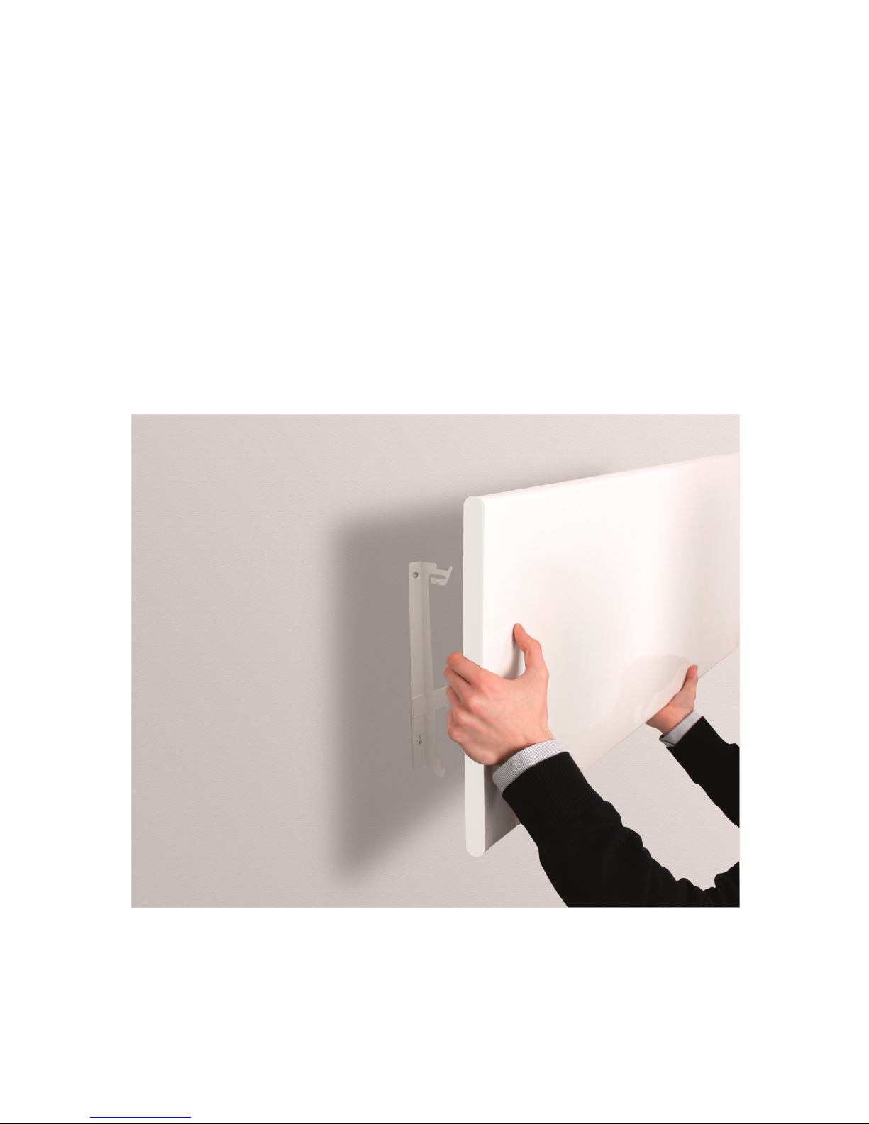
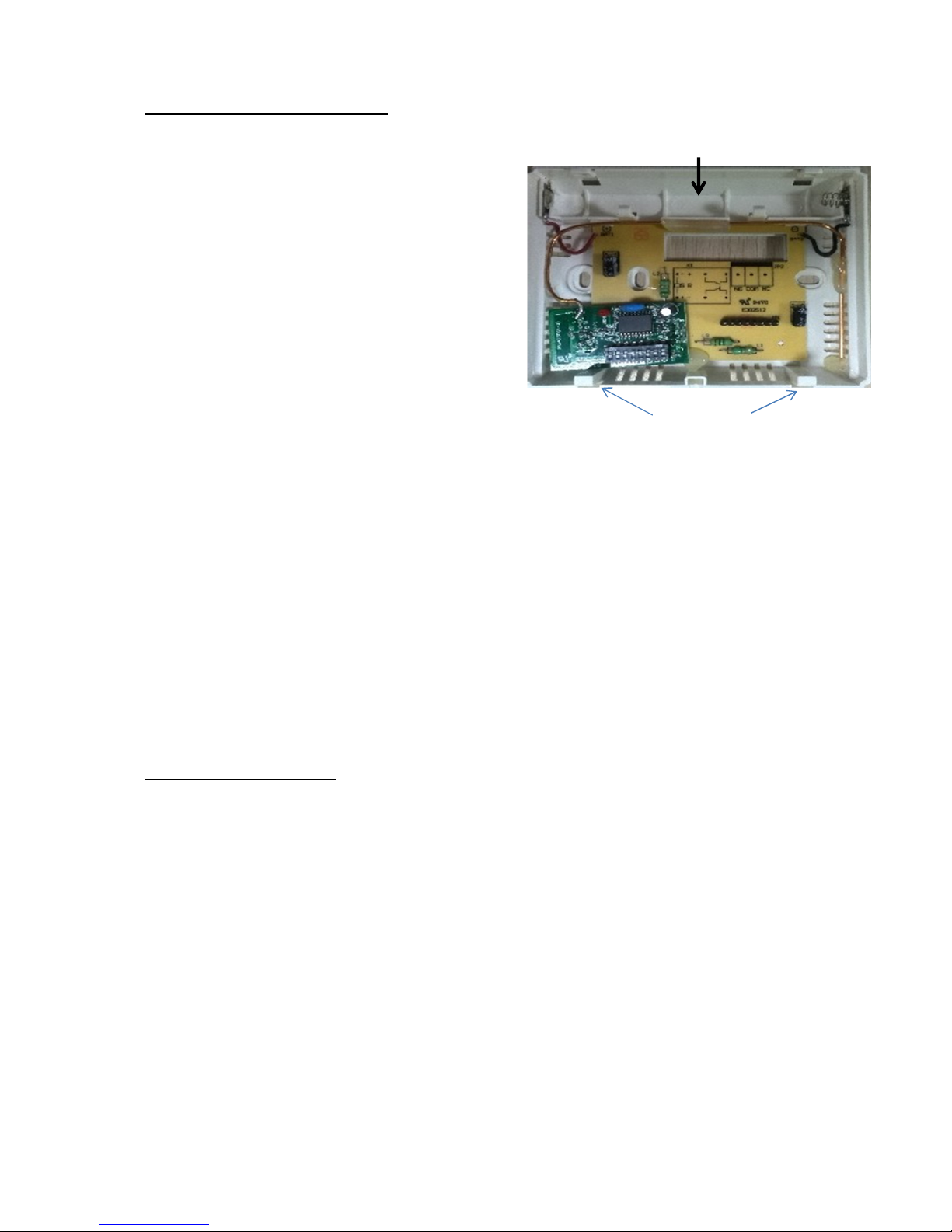
Wall mounting the device
The appliance must not be connected to the electricity whilst fitting to the wall
brackets.
lace the heater, with the front panel on the ground ensuring the surface you are placing it on
will not damage the heaters finish. If in doubt place a soft cloth down first. To release the wall
bracket, press the top part of the bracket on both sides at the same time the metal tabs slightly to
the left (Fig. 1) and hang the unit on the upper fixing of the wall bracket. Now lower the unit onto
the base lugs of the brackets.
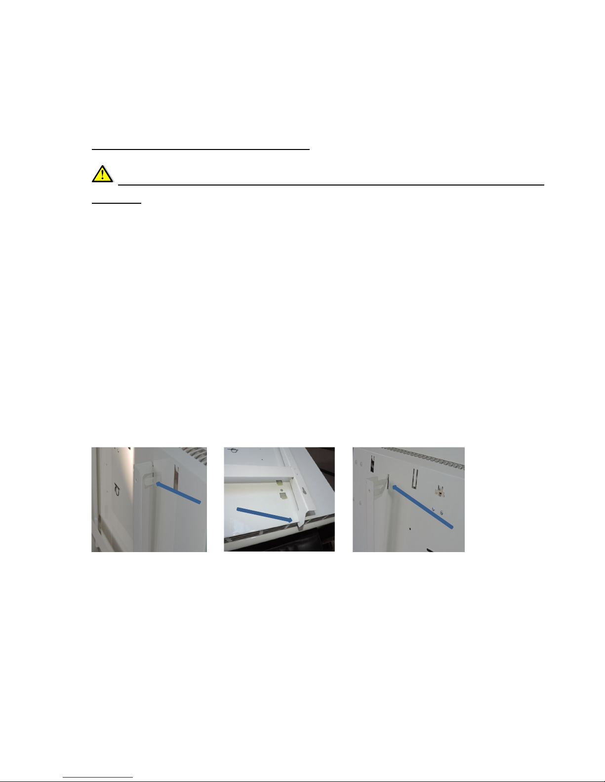
With the air vents to the top, lower the heater into the bottom hooks (Fig. 2) The centre tabs of
the bracket will then locate into the slots before the top tabs will locate and lock ( Fig. 3). ress
the device now facing the wall , then snap the two movable plate tabs and the device is attached
to the wall bracket.
Should the unit need to be removed from the wall, then proceed as follows. First disconnect the
appliance from the mains. Now you can then access up behind the unit , to the two upper vertical
struts and press there the same time the two movable tabs to the right until it clicks button up
( fig , 1). Now the device can be taken from the holder.
Fig 1 Fig 2 Fig 3
Note: To release the unit from the wall bracket. ress the top tabs in together (Fig. 1). The heater
can then be dropped forward and lifted clear of the bracket.
lease ensure the heater is disconnected from the electricity supply before removing the heater
from the wall bracket.
7
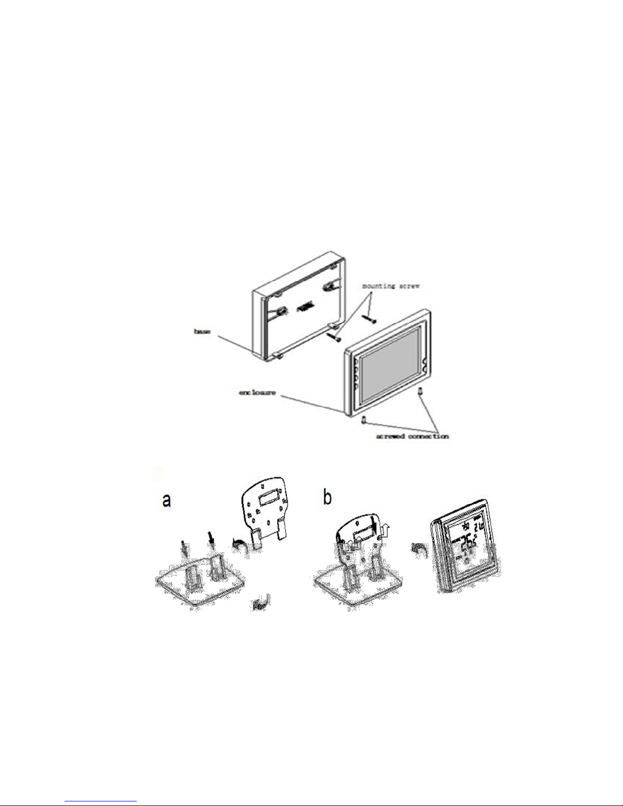
reparing the Remote Control (mounting, installation and battery replacement)
Wall mounting
Table stand for remote control (Optional Accessory)
8
Inserting the batteries
rocedure prior to first use or when changing batteries
•Remove the two screws at the bottom
•
Open short side of the remote control
•
Lift the display face carefully
•2 alkaline batteries 1.5 V IEC LR6 (AA)
•Insert the 2 batteries in the compartment.
•Note the correct polarity and carefully
close and replace retaining screws
+
Battery Compartment
-
2 Screws
1. Basic settings of the remote control
Turn "On" (the flame and clock icon is seen in the display) Remote On/Off button (1)
1) ress the clock button (2)
2) Use the ▲ or ▼ button (6/7) to set the exact current hour
3) ress the clock button (2) again and the minute digits will flash
4) Use the ▲ or ▼ button (6/7) to set the exact current minute
5) ress the clock button (2) again and the day of the week indicator (8) will flash
6) Use the ▲ or ▼ button (6/7) to set the current day of the week (1 = Monday)
7) ress the R button (4) and the entries will be stored.
2. Configuration Menu
The remote control has a configuration menu where the various basic parameters can be set,
depending on the preference of the users and their habits. roceed as follows:
ress the button (1) to ensure that the remote control is in "antifreeze" mode. A cold symbol (14)
must be visible on the screen. Now press the - (3) for about 3 seconds to move to the input
mode of the configuration menus. The large figure shown is setting number; the small figure to
the right is the adjustment for this setting. By pressing the arrow keys (6/7) you can adjust the
options until the desired selection is displayed. ressing the key again, the displayed value is
assumed for these parameters and the display changes to the next parameter. Continue selecting
until all 10 parameters are defined according to your wishes.
To exit from this menu, press the Start button (1) and return to the freeze protection mode or for
program execution, press the R-key (4) and enter run mode. If no key is pressed for 20 seconds,
the parameter menu is automatically exited.
9
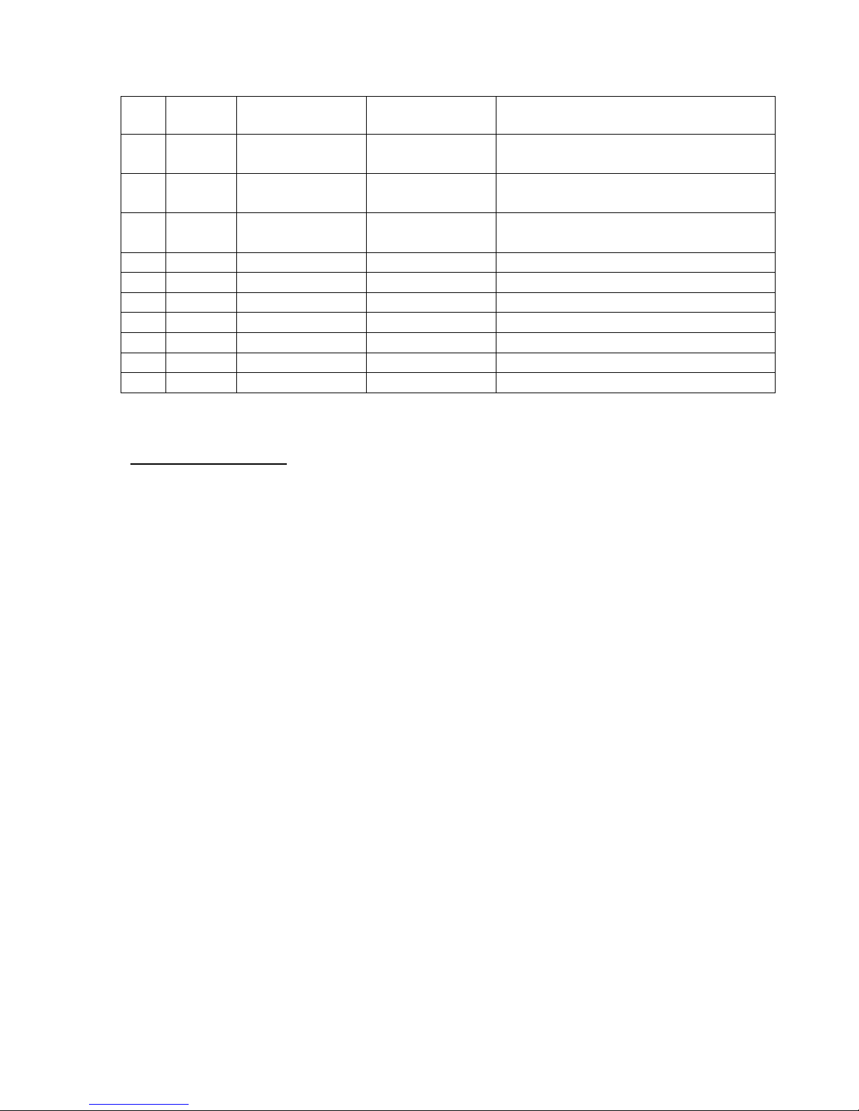
Default Settings
No. ress Factory Settings To Select ▲ or
▼
arameter Description
1 ③ “ ” 0 -3 --- +3 Displayed actual temperature can be
adjusted by 3 ° C or down
2 ③ “ ” 35
℃
℃℃
℃
18
℃
℃℃
℃
(64
℉
℉℉
℉
)—
35
℃
℃℃
℃
(95
℉
℉℉
℉
)
Selectable limit for maximum
temperature
3 ③ “ ” 5
℃
℃℃
℃
5
℃
℃℃
℃
(41
℉
℉℉
℉
)—
20
℃
℃℃
℃
(68
℉
℉℉
℉
)
Selectable limit for low temperature
4 ③ “ ”
℃
℃℃
℃
℃
℃℃
℃
/
℉
℉℉
℉
Display in
℃
℃℃
℃
or
℉
℉℉
℉
5 ③ “ ” FA FA/SL Heat option for fast or slow
6 ③ “ ” OO /OO This option is not possible in αlpha
7 ③ “ ” 24 12 or 24 Select 12 or 24 hour display
8 ③ “ ” 7 0 / 3 / 7 Three-time programs can be selected
9 ③ “ ” 6 4/ 6 Two switching time settings selectable
10 ③ “ ” 5 0 / 5 / 10 Mode backlight selectable.
Utilizing the settings
1. The calibrated measured temperature is displayed on the remote control (16) and can
be adjusted by +/- 3 ° C.
2. Upper temperature limit is displayed and can be adjusted (between 18 ° C / 64 ° F
and 35 ° C / 95 ° F).
Factory setting is 35 ° C / 95 ° F.
3. Lower temperature limit where the desired lower adjustable temperature limit can be
entered (between 5 ° C / 41 ° F and 20 ° C / 68 ° F).
Factory setting is 5 ° C / 41 ° F.
4. For (° F) or (° C) displayed option can be selected here.
5. Option for fast or slow heating.
-For quick heating use the FA selection. In this mode the heater will react immediately
when the desired temperature is 1 ° C above/below the set room temperature.
-For slow heating use the SL selection. In this mode the heater will react immediately
when the desired temperature is 3 ° C above/below the set room temperature.
6. This feature is not available on the alpha.
7. Display for times
Choice between 12 and 24 hours mode
8. Three program options for switching points and temperature per week to choose from:
-Select 7: All 7 days can be individually programmed
-Select 3: You can program three periods (5 weekdays + Saturday + Sunday)
-Select 0: No model programmed
-The factory setting is 7
10
9. Two options for switching times per day
-Choose 4: You have 4 switching times per day of the program .
-Select 6: You have 6 daily times.
The factory setting is 6.
10. The backlight of the display has 3 settings
0 = No backlight
5 = backlight for 5 seconds
10 = backlight for 10 seconds.
Commissioning
Now that the remote control has been prepared and the device is attached to the wall, the
connection can be made to the mains. This is done either by simply plugging the power cord into
the outlet, or by fixed wiring in a junction box. The latter must be executed by an appropriate
qualified professional. If the connection to the mains supply and the device is to be operated,
please proceed as follows:
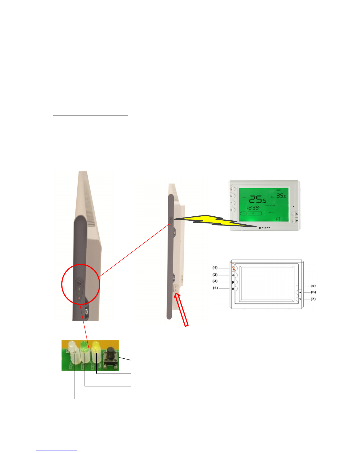
Heating control
(Receiver)
main switch
Receiver on / off button
Display C (Yellow LED)
B power (green LED)
Display (Red LED)
Wireless remote control
(Transmitter)
(1) On / Off / Anti-frost (5) Reset
(2) Clock
(3) rogram Set
(4) Confirmation program
(5) Reset
(6) Selection up
(7) Selection down

11
Receiver power button red LED (A): A short press will turn the red LED on/off indicating
supply status.
Load staus green LED (B): The green LED will illuminate when the heater is calling for
power.
Green LED (B) will also flash slowly to indicate when the heater is in an over-temperature
protection mode.
airing yellow LED (C): The yellow LED will illuminate when to show it is ready for pairing.
Before commencing with pairing make sure the heater is switched on at
the righthand side. The white switch should be pointing to the I symbol.
For pairing a single heater with a single remote control
1 Ensure the heater is turned on at the side and the control screen has batteries installed and is
turned off (showing system *).
1.1. After switching the heater on via the main switch, there should be no LED lights on the side
of the heater. If the red LED is on, turn it off by depressing the small on/off receiver power switch.
The heater is now ready for pairing with the remote control.
1.2. ress and hold the on/off receiver power switch for 3 seconds until the yellow LED lights up.
1.3. Take the remote control (turned off) and hold it a short distance from the heater control.
Now press the R button (4) on the bottom left hand corner for 5 seconds.
1.4. The back light on the screen will illuminate when the heater is paired.
1.5. Turn the heater red LED on by depressing the small on/off receiver power switch. Then turn
the control screen on at the top left hand corner and increase the room temperature setting to
maximum. The green LED on the heater will then illuminate to show the heater is calling for
power.
1.6. Revert to your chosen temperature settings.
12
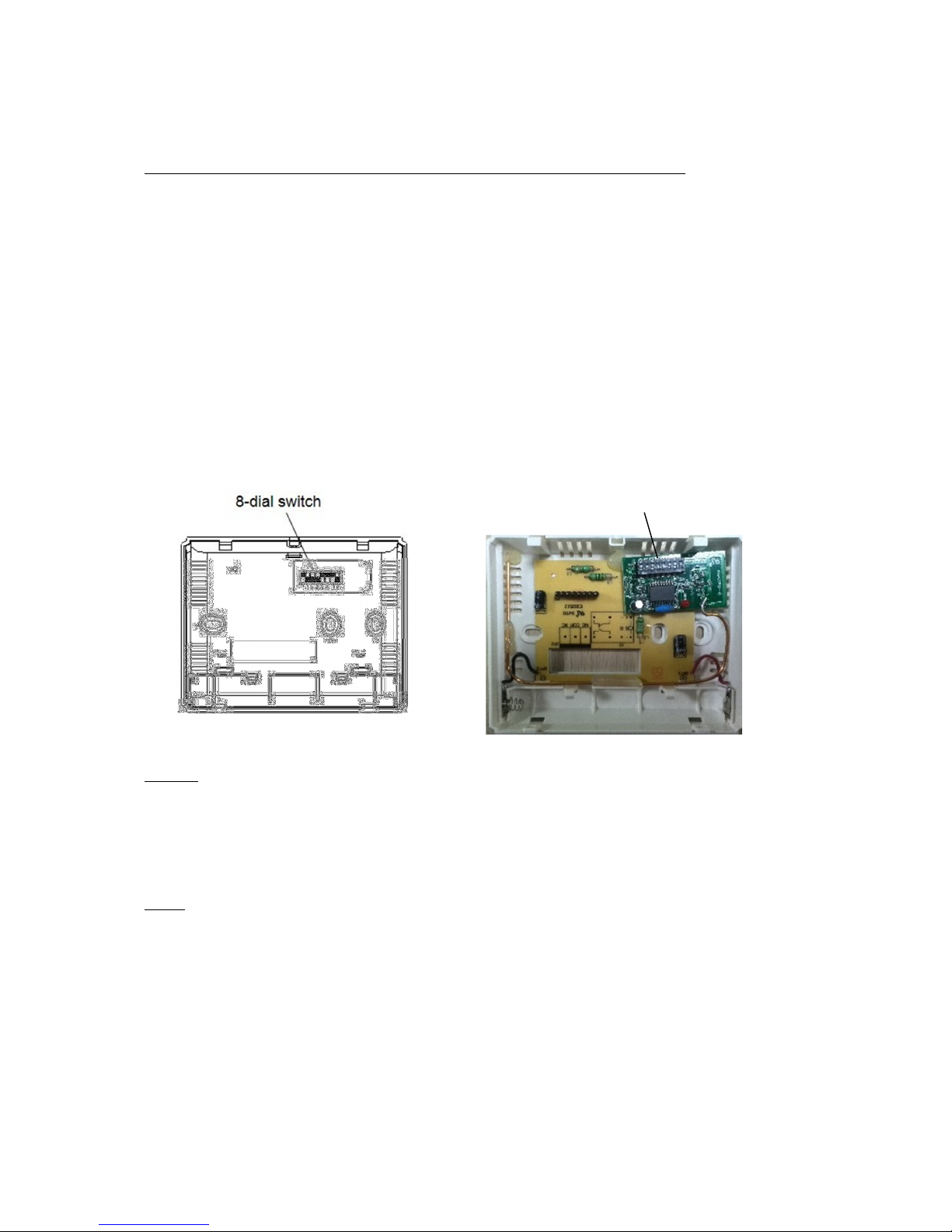
When operating multiple devices with multiple remote controls
When using more than one remote control you will need to give each control specific
assignments to avoid any malfunctions to individual units.
This is done by assigning corresponding codes by remote control. lease proceed as follows:
Open the casing of the remote control by removing the two small screws. You will see a bar with 8
selectors (see illustration below). In default, all switches are set the same for delivery. Simply slide
one or more of the switches up to make your own unique code for the multiple heaters used from
one screen. The screen sets the frequency, the heaters will accept this and only work through this
controller.
After these changes, close the cover of the remote control again and make the match between
unit and remote control before, as described above.
Note1:
The range of the remote control in an open area is about 100 m. In buildings, the range is
significantly shorter, and depends on many factors. On average a range of about 40m typically ,
unless specifically screened by, for example, Metal or another interference field.
Note:
Settings saved in the remote control are not lost when changing the battery as it is equipped with
an E ROM.
8
dial switch
13
Setting the heater by remote control after pairing is complete
For an explanation to the symbols seen on the screen of the remote control, please refer the end
of this manual.
Temperature only setting without time control
1 Turn on the remote control at the top left hand corner of the screen.
2 Increase the temperature setting in the top right hand corner of the screen to your desired
preference. This can be done in 0.5 ° C increments by pushing the up arrow (6). The hand symbol
is visible on the display showing it is working in manual operation.
5 The green LED on the heater will illuminate to show it is calling for power.
6 To exit the manual operation either simply turn the control screen off in the top left hand
corner or push the (R) button to revert to the timed mode .
Note:
a) The manual temperature adjustment is active until the next input automatic switching time is
achieved. The controller then switches back to timed operation.
b) You can prevent this from happening by pressing the (R) button for 3 seconds until the symbol
of a key (18) appears below the figure for the current day of the week This means that the
automatic program is temporarily suspended and the manually set temperature request is
executed. This continues until the R-key (4) is pressed briefly. The key symbol disappears and the
automatic scheduled expiration is now reinstated.
Temperature setting with time control
For a time-controlled temperature setting with predefined default values, proceed as follows:
The remote control includes a factory-preset default. If you are satisfied with the predefined
default values shown in the table below and you do not want to change anything, simply press
the R button (4) on the remote control. The control will return to the default operating state.
The following values are set:
Wake Up
Leaving home 1
Return 1
Leaving Home 2
Return 2
Nights Sleep
Start-
time
Temp.-
value
Start-
value
Temp.-
value
Start-
value
Temp.-
value
Start-
value
Temp.-
value
Start-
value
Temp.-
value
Start-
value
Temp.-
value
6:00 21
℃
8:00 16.5
℃
12:00 21
℃
14:00 16.5
℃
18:00 21
℃
22:00 16.5
℃

14
If, however, you would like to change any individual, or indeed all preset values, please follow the
instruction below.
•Firstly decide if you would like to use the factory settings with 3 x on/off each day or your
own bespoke settings with 2 x on/off each day. To change the factory default see the
configuration menu on page 8 of this instruction.
•Turn on remote control at the on/off button (1)
•ress the -key (3). #1 will appear in the screen indicating the first (On).
•The time will be flashing at the top of the screen. This can be adjusted up or down by
pushing the keys (6/7).
•When your time is set push the clock button (2). This will save the start time and move
across to the temperature required.
•This can again be adjusted by pushing the keys (6/7). When this is complete push the -key
(3) to move across to the next programme.
•#2 will now be flashing indicating the first off setting.
•Firstly set the time to end the first programme.
•Now push the clock button (2) to set the temperature required when the heater is off.
•This can be set as low as 5°C meaning the heater will only activate should the room
temperature drop below this figure. If you would like to reduce this further see the
configuration menu on page 8 of this instruction.
•Follow the guidelines above through every day until complete.
•If you wish to escape this menu at any time simply push the (R) button.
Frost rotection mode.
Simply turn the rempote control screen off in the top left hand corner. The screen should be
showing the time, current room temperature and system*.
This will leave the heaters off their set programmes and only activate should the room
temperatures fall below 5°C.

15
Holiday Mode.
•With the screen turned on push and hold the -key (3) for 3 seconds.
•A small suitcase will appear in the top of the screen indicating the holiday mode is active.
•ush the clock button (2) to increase the number of days required up to a maximum of 99
days.
•The –key (3) can be pushed to reduce the amount of days.
•Now set the desired temperature by pressing the arrow keys (6/7) on the value that you
want to keep in your absence. The factory setting is 10 ° C.
•Finally press the R-key (4) to record the set data.
•When the set days of absence are finished the controller will automatically return to the
programmed operation.
Reset Function
On the right front of the remote side of the display, there is a small hole (5) for the reset (return
to factory setting). In the event that a factory reset is necessary, use a corresponding object (such
as a straightened paper clip) and run this gently into the slot, and press so that the inner knob.
Remove the item carefully back from the opening. The remote control is now reset to the factory
delivered state.
Operation of αlpha remote heater without the
remote control
Although the α
αα
αlpha heater is designed to run in conjunction with the remote control screen, there
may be instances where the heater needs to be used without the screen. This should be only in
emergencies or for short periods of time. This could be due to the following:
•Forgotten to buy batteries despite the low battery indicator flashing.
•Control screen is missing or damaged.
•
In these circumstances simply turn the power on to the heater at the main switch at the rear.
With the red LED turned off, push and hold the receiver on/off button for 10 seconds. Keep it
pushed in even when the yellow LED pairing light illuminates until the green LED lights up
denoting „calling for power“. Remember the heater is under no external control whatsoever and
is your reponsibility to switch it off manually.
16
Finally, check your program inputs
Before you can run a program with newly entered data, you should be sure that everything has
been entered, as it was planned. Always check before executing the entries.
ress the -key (3). It will now show the set input information for each on/off and day
If the entry is correct, press the button (3). You can also make changes and then press the key.
roceed as explained in previous chapters, the entire input for the week.
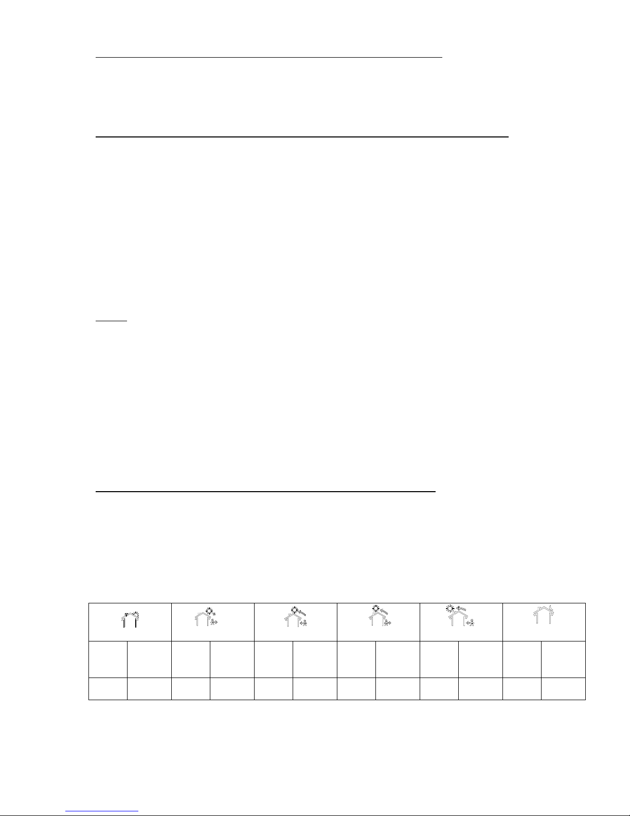
The chart below can be filled in to remind you of your new default settings.
Wake Up
Leaving home1
Return 1
Leaving Home 2
Return 2
Nights Sleep
Start
Time
Temp
Value
Stop
Time
Temp
Value
Stop
Time
Temp
Value
Start
Temp
Temp
Value
Start
Time
Temp
Value
Stop
Time
Temp
Value
Mon.
Tue.
Wed.
Thu.
Fri.
Sat.
Sun.
General Technical Voltage 230V/50Hz
Class 1 must be fully earthed
rotection class I 20 not for use in bathroom zones 1 or 2.
Colours: RAL 9010 white – RAL9005 black – Both 30% polyester matt
Remote control 2x1,5V IEC LR6 (AA) alkaline batteries
Battery warning indicator
Error warning signal loss Frequency 433MHz

17
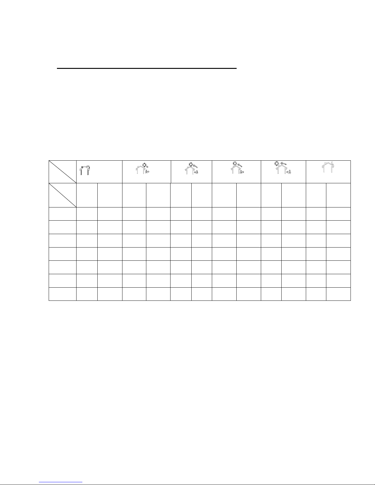
Schematic drawing for
αlpha
remote
Scheme
number
Symbols in the display
αlpha
remote
14
Wake
up
On 1
Leave
Off 2
Return
lunch
On 3
Leave
Off 4
Return
On 5
N
ight time
Off 6
15
Frost
rotection
System
on
Flashing
flame calling
for heat
Manu
al
override
Timing mode
rogram
setting
1 On/off frost protection button
2 Timer setting button
3 rogram setting button
4 Confirmation and return button
5 Reset to default settings
6 Increase upwards
7 Decrease downwards
8 Week days 1 - 7
9 Actual time and pregrammed time
10 AM/ M when in 12 hour mode
11 Requested room temperature
12 Low battery indicator
13 Temperature shown in °C or °F
Sytem Error
16
Actual room
temperature
17
Holiday
mode
18
Sytem lock
(1 7 )
(1 6 )
(1 5 )
(1 8 )
(1 4 )
(1 3 )
(1 2 )
(1 1 )
(9 ) ( 1 0 )
(8 )
18
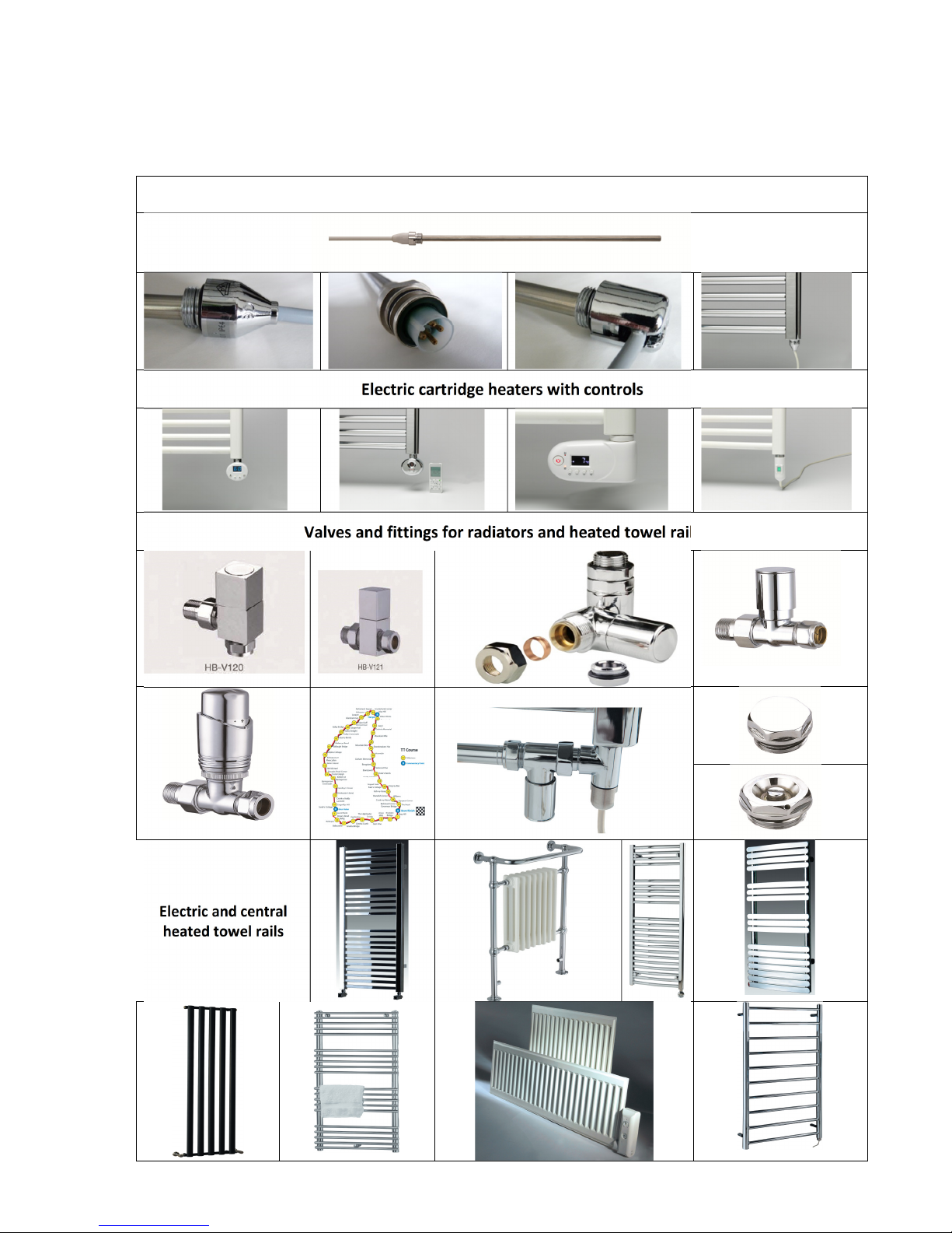
Other Sol*Aire products and accessories for electric heating
Electric cartridge heaters without control
Electric cartridge heaters with controls
Valves and fittings for radiators and heated towel rails
Electric and central
heated towel rails

19
For further αlpha remote accessories, components and other devices from the field of electric heating also
consult our website or contact directly with us. We are always happy to help.
Technical Data
Voltage
:
230V / 50 Hz
Insulation class:
I
rotection class:
I 20
Colours:
White (RAL9010)
Black (RAL9005)
ower, Amps, Weight and Dimensions of the Radiators:
roduct- Code
Colour Code
ower
(W)
Amps
(A)
Weight Overall dimension
L x W x H (mm)
Net
(kg)
I
nc
l.
packing
(kg)
White A05HW 500 2.2 5 6 660 x 82 x 400
Black A05HB
White A10HW 1.000 4.3 6 7 787 x 82 x 400
Black A10HB
White A15HW 1.500 6.5 7 8 1037 x 82 x 400
Black A15HB
White A20HW 2.000 8.7 8,5 10 1337 x 82 x 400
Black A20HB
White A25HW 2.500 10.9 10 12.5 1637 x 82 x 400
Black A25HB
Cable colour:
Cable end:
White
lug or stripped
(depending on order)
Remote Control
Wireless, battery powered, ~100m range (no obstacles), 6 buttons, 1 reset.
Frequency 433 MHz; operation at 0 to +50°C; storing at -10 bis +60°C. Case white.
Dimension:
115x90x28 mm
Batteries:
2 x AA-LR6 IEC 1,5V alkaline
20
αlpha
remote
Electric panel radiators
Sol*Aire Heating roducts Limited
New Row
Eppleby
North Yorkshire
DL11 7AW
Tel: 01325 717899 Fax: 01325 718065 email info@solairehp.co.uk Web: www.solairehp.co.uk
.
Table of contents
Popular Electric Heater manuals by other brands

HUUM
HUUM STEEL Installation and operation manual

EQUATION
EQUATION NTH20-17BR Legal and Safety Instructions

REMKO
REMKO ELT 18-HT Operation manual

Broan
Broan 6201 instructions

Heatscope
Heatscope PURE Original installation and instruction manual

Olimpia splendid
Olimpia splendid Caldorad Instructions for installation, use and maintenance


HUUM
HUUM STEEL quick start guide

Vents
Vents HE 500x300-5.1-1 installation instructions

Kenwood
Kenwood 6708EP Important instructions

decorflame
decorflame QC810 instruction manual

Electrolux
Electrolux ECH/T-1000 E EEC user manual

Chromalox
Chromalox PG417-3 Installation, operation and renewal parts identification