REMKO ELT 18-HT User manual

Edition GB – I09
REMKO ELT 18-HT
High temperature
electric heater
Operation · Technology · Spare parts


3
Contents
Carefully read this original operating manual prior
to commissioning / using the units!
This operating manual is a translation of the German original.
These original instructions are an integral part of the unit and
must always be kept in the vicinity of the installation location
or on the unit itself.
Subject to modifications; no liability accepted for errors or misprints!
Unit description 4
Safety notes 4
Commissioning 5-6
Shutdown 6
Operation with a warm air hose 6
Care and maintenance 6
Troubleshooting 7
Intended use 7
Customer service and guarantee 7
Environmental protection and recycling 7
Electrical wiring diagram 8
Maintenance protocol 9
Exploded view of the unit 10
Spare parts list 11
Technical data 11

4
REMKO ELT 18-HT
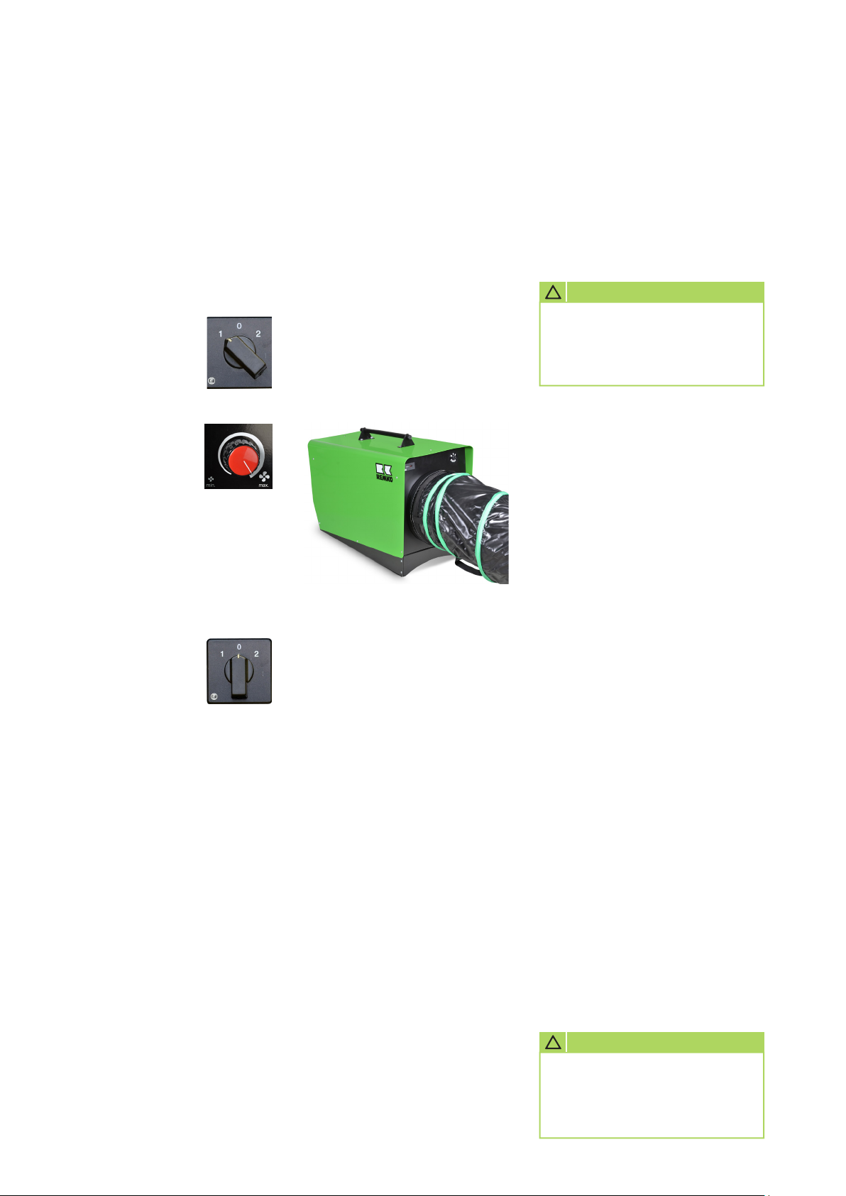
The units are portable electric
heating units for industrial
applications at various locations.
The units are operated exclusively
with electric power and have been
designed for high-temperature
applications with an air outlet
temperature of up to 120°C.
The air outlet temperature is
altered by manually adjusting the
fan speed.
The units can be operated using no
more than one high-temperature
hose (accessory) with a ø of
305 mm and a length of 7.6 m.
The units are equipped with
special-purpose, highly efficient
electrical heating coils for
immediate and consistent heat
generation, low-maintenance axial
fans, a safety thermostat, a room
thermostat socket and a mains
cable with earthed safety plug.
The units conform to the
fundamental health and safety
requirements of the appropriate
EU stipulations.
The units are dependable and offer
ease of operation.
The units may be used among
other things for the following:
■
Drying heat-resistant materials
■
Generating process heat for
industrial applications
■
Hardening plastics
■
Pest control
■
Drying out construction
work / heating
Safety notesUnit description
The units have been subjected
to extensive material, functional
and quality inspections prior to
delivery. However, dangers can
arise from the units if they are used
improperly or not as intended by
untrained personnel!
Please observe the following notes:
■
In the event of defects that
endanger the operational safety
of the unit, operation must be
discontinued immediately
■
Observe the respective local
electrical regulations and the
necessary safety measures when
using the units
■
Maintain safety distances to
combustible materials
0.5 m at the side of the unit and
on the air inlet side
2.0 m on the air outlet side
■
An unobstructed air inlet and air
outlet must be guaranteed at all
times
■
The units must not be covered
during operation
■
Never insert foreign objects into
the units
■
The units must not be operated
in the vicinity of bathtubs,
showers, swimming pools etc.
■
The units must not be operated
directly below a wall socket
■
The units must not be exposed
to direct jets of water
CAUTION
Extensions to the connection
cable must only be conducted
by authorised specialist
electricians, taking into
consideration the unit capacity,
cable length and local use.
■
The units must not be installed
or operated in potentially
flammable or explosive
environments
■
The units must not be operated
in locations where:
combustible gaseous, air or
dust-air mixtures could be
produced; flammable small parts
could be sucked in, set alight on
the heating coil and blown out
in a glowing state
■
Flooring and ceilings must be
fire retardant
■
The air inlet and outlet must not
be constricted
■
The relevant safety guidelines
of the Employer's Liability
Insurance Association or
property insurer must be
observed
■
The units must be installed
in a stable position and must
not topple over or slide out of
position during operation
■
The units must not be left
unattended during operation
■
The units must not be operated
in an environment with an
ambient temperature of over
60°C
■
All electrical cables for the
units must be protected against
damage, even damage caused
by animals

5
Commissioning
One person, who has been
adequately trained in the handling
of the units, should be tasked with
the operation and monitoring of
the units.
The units are equipped with
a 3-stage operating switch.
1. Move the operating
switch to the “0”
position.
2. Connect the unit's
power plug to
a properly installed
32 A mains socket.
Heating with a special
purpose HT room thermostat
or duct thermostat (accessories)
The units operate fully
automatically and according to the
air outlet/room temperature.
1. Pull out the strapping plug [2].
2. Connect the plug [3] of the
relevant thermostat to the
thermostat socket [1] on the
unit.
3
1
NOTE
The electrical connection for
the units must be made at
a separate feed point with
a residual current device in
accordance with VDE 0100,
Section 55.
3. Place the probe in a suitable
position according to the type
of thermostat used.
The thermostat probe must not
be located directly in the warm
air flow and must not be placed
directly on the cold floor.
4. On the room thermostat, set
the temperature required for
the application at hand.
5. Move the operating
switch to the “2”
(Heating) position.
GREEN indicator light on!
Heating without room
thermostat
The units are operating in
permanent operating mode.
1. Connect the supplied strapping
plug [2] to the thermostat
socket [1] on the unit.
2. Move the operating
switch to the “2”
(Heating) position.
GREEN indicator light on!
2
1
Adjust the air outlet temperature
Upon start-up, set the fan speed to
the maximum setting.
If the
YELLOW
light does not light
up after an operating time of approx.
5 minutes, please decrease the fan
speed by approx. 10%.
If the
yellow
light has still not lit up
after another 5 minutes, repeat the
previous procedure until the
YELLOW
HT operating light
is continuously lit.
The unit has now been optimally
adapted to the ambient conditions
and is operating in high-temperature
mode at approx. 100-120°C.
Safety in the event of excessive
temperature
If the operating conditions change in
permanent operating mode and the
temperature at the air outlet exceeds
120°C, the unit reverts to a heating
capacity of 12 kW automatically.
The
GREEN indicator light
goes out,
the
YELLOW
one remains lit.
In this case, we recommend checking
the operating conditions or increasing
the speed by 10% until the max.
heating capacity is reactivated.
GREEN
indicator light on!
In the event of serious heat build-up
caused by, for example, a constricted
air outlet, a lack of unrestricted air
intake or the fan being at a standstill,
the safety thermostat switches the
unit off. This needs to be manually
unlocked once the fault has been
rectified and the unit has cooled
down.
Operating lights
1= HT mode
YELLOW
2= max. heating capacity
GREEN
3= STB fault
RED
1 2 3

6
REMKO ELT 18-HT
Operation with
warm air hose
The units are equipped
with a special-purpose high
performance axial fan.
This opens up the possibility of
operating the unit with an HT
warm air hose with a ø of 305 mm
and a length of 7.6 m to transport
the heated air efficiently and
effectively to the place where it is
required.
Only warm air hoses (accessories)
that have been approved by
Remko may be used as these have
been designed specifically for these
high temperature units.
Information about the assembly of
the warm air hose
■
Only special-purpose high-
temperature hoses may be used
■
Make sure that the unit’s outlet
nozzle is securely fastened
■
There should be no kinks or
bends in the hose lines in order
to prevent hot-spots forming
■
Make sure that the air outlet at
the end of the hose is clear at
all times
Regular care and observation
of some basic requirements will
ensure trouble-free operation and
a long service life of the units.
■
In accordance with the
operating conditions, the units
must, if necessary, be checked
at least yearly by a specialist
to ensure that they are in a
condition that is safe to use
■
Keep the units free of dust and
other debris
■
Only clean the units with a dry
or moistened cloth
■
Never subject to direct jets of
water.
e.g. pressure washers etc.
■
Never use abrasive or solvent-
based cleaners
■
Use only suitable cleaners, even
for heavy contamination
■
Check the inlet and outlet grille
for contamination on a regular
basis
■
Check the safety equipment
and protective devices on
a regular basis
■
Be careful not to damage
the temperature controllers’
probes or capillary tubes when
removing or mounting the
protective exhaust grid
Care and maintenance
1. Move the operating
switch to the “0”
position.
2. If the units are inactive for long
periods, disconnect them from
the mains power supply.
3. The supply air fan may run
on to cool the units and only
switch off after the cooling
down phase is complete.
4. If the units need to be stored,
clean them and, if necessary,
cover them with a plastic sheet/
film or cotton cloth and store
in a sheltered and dry storage
location.
Shutdown
Ventilation only operation
Only the supply air fan operates
in this setting. Thermostatic
regulation and heating operation
are not possible in this operating
mode.
Move the operating
switch to the “1”
position.
The fan speed can
also be adjusted in this
operating mode.
An electrical safety check must
be carried out in accordance
with VDE 0701 after any work
on the units.
CAUTION
!
Before undertaking any work
on the units, the power plug
must be removed from the
mains socket.
CAUTION
!

7
Troubleshooting Customer service and
guarantee
The units are designed exclusively
for heating and ventilation
purposes in industrial or
commercial use (not for living
space heating in private use) on
the basis of their structural design
and equipment.
The units must only be operated
by appropriately instructed
personnel.
With non-observance of the
manufacturer's specifications, the
respective local legal requirements
or after arbitrary alterations to the
units, the manufacturer shall not
be liable for resulting damages.
Intended use
As a prerequisite for any guarantee
claims to be considered, it is
essential that the ordering party
or their representative complete
and return the "certificate of
guarantee" to REMKO GmbH &
Co. KG at the time when the units
are purchased and commissioned.
The units were tested at the
factory several times to verify their
correct function.
However, if malfunctions should
arise that cannot be remedied by
the operator with the assistance of
the troubleshooting section, please
contact your specialist dealer or
contractual partner.
Disposing of packaging
When disposing of packaging
material, please consider our
environment.
Our units are carefully packed
and delivered in sturdy transport
packaging made from cardboard
and polystyrene.
The packaging materials are
environmentally-friendly and can
be recycled.
By recycling packaging materials,
you make a valuable contribution
to the reduction of waste and
conservation of raw materials.
Therefore, only dispose of
packaging material at appropriate
collection points.
The unit (fan) does not start.
1. Check the mains fuses on site.
2. Check the control fuse on the
rear panel of the unit.
3. Check the power plug.
4. Check the operating switch.
5. Check that the air circulating fan
can move freely.
The unit does not heat up.
1. Check the operating switch.
2. Check that the contactors are
functioning correctly.
3. Check that the temperature
controller is functioning correctly
and check the capillary tube for
damage.
4. Check whether the STB has
triggered or check the capillary
tube for damage.
5. Check that the thermostat and
the strapping plug are in place.
6. When operating the unit with
a room thermostat, set the
thermostat to a temperature
that is above the room
temperature.
If all of the functional checks
have been carried out without
any findings, please contact an
authorised service station.
NOTE
Adjustment and maintenance
work may only be carried out
by authorised and qualified
technicians.
NOTE
Operation other than the types
listed in this operating manual
is prohibited.
With non-observance, any
manufacturer liability or
guarantee claims are voided.
Environmental
protection and
recycling
Copyright
The redistribution, even in part,
or the use of this documentation
for purposes other than intended
is prohibited without the written
authorisation of
REMKO GmbH & Co. KG
.
CAUTION
!
Safety devices
must not be bypassed
or disabled.
CAUTION
!

8
REMKO ELT 18-HT
Electrical wiring diagram
Legend:
C1 = Condenser
HW = Special-purpose heating insert
KL = Connection terminal strip
K1 = Contactor 1
K2 = Contactor 2
M = Fan motor
NK = Aftercooler thermostat
RT = Thermostat receptacle
S1 = Operating switch
STB = Safety thermostat
TH = Temperature controller
TL = Temperature controller
We reserve the right to modify the dimensions and design as part of the ongoing technical development process.
C1
H1
rG ün
la kB c
X2:3
:4X2
KL:L1
4
1
4
2
TH
dT/120°C
CTL
dT/80°C
F1
p6.3Am
NN
N
H2
eG lb
N
H3
tRo
3
1
2
M
aunBr
Blau
Blau
2U
U1
X2 2:
1
4
2
TBS
/ 0dT 10 °C
Z
r unB a
Fuse
13
14
X2:1
STB
100°C
HT-Betrieb
ab 80°C
Grünlicht an = 18 kW Power
ab 120°C Grünlicht aus = 12 kW Power
HW1
HW2
400V/3~N/50Hz
1 2 4 53
L1 L2 L3 N PE
12 kW 6 kW
EMV Filter
Poti 150kW
Leistungsregler
13 A2
A1
A2
A1
14
135
2 4 6 2 4 6
135
1 0 2
S1
2
1
1 2
A1
A2
A1
A2
12
KN
dT/37°C
5634
1 2
3X
3X
~
KL
K2K1
K2K1
K2
K1
RT
h
N
Betriebs-
stundenzähler
optional

9
Maintenance protocol ✍
Comments:.....................................................................................................................................................
............................................................................................................................................................................
............................................................................................................................................................................
1. Date: ..............
..............................
Signature
2. Date: ..............
..............................
Signature
3. Date: ..............
..............................
Signature
4. Date: ..............
..............................
Signature
5. Date: ..............
..............................
Signature
6. Date: ..............
..............................
Signature
7. Date: ..............
..............................
Signature
8. Date: ..............
..............................
Signature
9. Date: ..............
..............................
Signature
10. Date: ............
..............................
Signature
11. Date: ............
..............................
Signature
12. Date: ............
..............................
Signature
13. Date: ............
..............................
Signature
14. Date: ............
..............................
Signature
15. Date: ............
..............................
Signature
16. Date: ............
..............................
Signature
17. Date: ............
..............................
Signature
18. Date: ............
..............................
Signature
19. Date: ............
..............................
Signature
20. Date: ............
..............................
Signature
Unit to be maintained only by authorised specialists in accordance with the statutory regulations.
Unit type: .................................. Unit number: ...................................
1 2 3 4 5 6 7 8 9 10 11 12 13 14 15 16 17 18 19 20
Unit cleaned - outside -
Unit cleaned - inside -
Fan blade cleaned
Protection grid cleaned
Safety equipment checked
Safety devices checked
Unit checked for damage
All fastening screws checked
Electrical safety check
Test run

10
REMKO ELT 18-HT
Exploded view of the unit
We reserve the right to modify the dimensions and design as part of the ongoing technical development process.

11
Spare parts list
Technical data
1) Noise level measurement DIN 45635 - 01 - KL 3
Series ELT 18-HT
Nominal heat capacity kW 18
Switchable heating capacity kW Thermodynamic
Air volume m3/h 750-1600
Air outlet temperature °C up to 120
Power supply V/Hz 400/3~N/50
Max. rated current A 27.8
Max. power consumption kW 18.5
Electrical protection (provided by the customer) A (slow) 32
Sound pressure level LpA 1m 1) dB (A) 72 (68)
Dimensions: Length mm 880
Width mm 355
Height mm 500
Weight kg 25.2
No. Designation EDP no.
22 Terminal block 5er (16mm²) 1101501
23 Grommet for mains cable 1101502
24 Fan motor with blades 1107992
25 Condenser 1102716
26 “RED” light (STB fault) 1101503
27
“GREEN” light (max. heating capacity)
1101504
28 “YELLOW” light (HT mode) 1101505
29 Thermostat receptacle assembly 1101018
30 6.3 A control fuse 1101506
31 Speed controller adjusting knob 1101192
32 Operating switch 1-0-2 1101507
33 Speed control film 1101508
34 Air-inlet grille 1107994
35 Mains cable with plug 1107962
36 M012 speed control 1101100
37 Speed controller 1101103
38 Safety thermostat STB 1101197
39 Protective exhaust grid 1101353
Not ill.
Thermostat plug 1101020
Not ill.
Strapping plug 1101019
Not ill.
Operating hours counter 1105515
No. Designation EDP no.
1 Transport handle 1101482
2 Reinforcement plate 1101483
3 Outer casing ELT 18-HT 1101484
3a Outer casing ELT 18-HT (Inox) 1101485
4 Front panel with outlet nozzle 1101486
5 Floor panel 1101487
6 Front plate of floor panel 1101488
7 Support plate, right 1101489
8 Insulating shell 1101490
9 Heating insert assembly 1101491
10 Back wall 1101492
11 Support plate, left 1101493
12 Inner casing with outlet cone 1101494
13 Cover plate for STB 1101495
14 Mounting plate 1101496
15 Terminal block 6er (6mm²) 1101497
16 Contactor 1101021
17 Aftercooler thermostat 1104065
18 Retainer bar T-probe 1101498
19 Control thermostat with probe 1101499
20 Safety clamp for mains cable 1101500
21 EMC filter 1101101
When ordering spare parts, please state the EDP no., unit number and type (see name plate)!

Consulting
Thanks to intensive training,
our consultants are always
completely up-to-date when it
comes to technical expertise.
This has given us the reputation
of being more than just an
excellent, reliable supplier:
REMKO, a partner who helps to
solve problems.
Sales
REMKO offers not just a well-
established sales network both
nationally and internationally, but
also has exceptionally highly-
qualified sales specialists.
REMKO employees in the
field are more than just sales
people: above all, they must
be advisers to our customers
in air conditioning and heating
technology.
Customer service
Our units operate precisely
and reliably. However, in the
event of a malfunction REMKO
customer service is quickly on the
scene. Our extensive network of
experienced dealers guarantees
quick and reliable service.
REMKO INTERNATIONAL
... and also right in your neighbourhood!
Take advantage of our experience and advice
REMKO GmbH & Co. KG
Klima- und Wärmetechnik
Im Seelenkamp 12 D-32791 Lage
Postfach 1827 D-32777 Lage
Telephone +49 5232 606-0
Fax +49 5232 606-260
E-mail [email protected]
Internet www.remko.de
We reserve the right to make technical changes and provide no warranty as to the accuracy of this data!
Table of contents
Other REMKO Electric Heater manuals

REMKO
REMKO ELT 3-2 User manual

REMKO
REMKO ELT 18-S Installation instructions

REMKO
REMKO EM Series User manual

REMKO
REMKO ELT Series User manual

REMKO
REMKO EM Series User manual

REMKO
REMKO ELT 9-6 User manual

REMKO
REMKO ELT Series User manual

REMKO
REMKO ELT Series User manual

REMKO
REMKO ELT Series User manual

REMKO
REMKO ELT 18-S User manual
Popular Electric Heater manuals by other brands

Harvia
Harvia MDA165/200G Instructions for installation and use

Cooper & Hunter
Cooper & Hunter DOMESTIC CH-1000 EC instruction manual

Focal Point
Focal Point Umbria Installation and user instructions

Air King
Air King 1DKX3/8900 operating manual

TriStar
TriStar KA-5016 instruction manual

Solaire
Solaire alpha user manual