Solar Energy FWS 20 Quick guide
Fresh Water Station
Installation and
Instruction manual
FWS 20
For tradesman
Accurately read before installing
EN

2E & OE, subject to change without notice.
Usage1 . . . . . . . . . . . . . . . . . . . . . . . . . . . 3
Safety instructions and symbol legend2 3
Safety instructions2.1 . . . . . . . . . . . . . . . . . 3
Symbol legend2.2 . . . . . . . . . . . . . . . . . . . 4
Scope of delivery3 . . . . . . . . . . . . . . . . . . 4
Provisions4 . . . . . . . . . . . . . . . . . . . . . . . . 5
Statutory provisions4.1 . . . . . . . . . . . . . . . 5
Manufacturer’s specifications4.2 . . . . . . . . 5
Technical data5 . . . . . . . . . . . . . . . . . . . . 6
Installation6 . . . . . . . . . . . . . . . . . . . . . . . 7
Installation on buffer tank6.1 . . . . . . . . . . . 7
Wall fastening6.2 . . . . . . . . . . . . . . . . . . . . 8
Hydraulic installation6.3 . . . . . . . . . . . . . . . 9
Circulation unit (optional)6.4 . . . . . . . . . . . 10
Design of circulation unit6.4.1 . . . . . . . . . . . . . . 10
Installation of circulation unit6.4.2 . . . . . . . . . . . 11
Electric connection of circulation unit6.4.3 . . . . . 11
Operating modes of circulation unit6.4.4 . . . . . . 12
Initiation7 . . . . . . . . . . . . . . . . . . . . . . . . 13
Malfunctions8 . . . . . . . . . . . . . . . . . . . . 14
No hot water8.1 . . . . . . . . . . . . . . . . . . . . 14
No circulation8.2 . . . . . . . . . . . . . . . . . . . 15
No/wrong switching times8.3 . . . . . . . . . . 15
Constant circulation mode8.4 . . . . . . . . . 15
Fresh Water Station leaks8.5 . . . . . . . . . . 15
Terms of warranty9 . . . . . . . . . . . . . . . . 16
Appendix10 . . . . . . . . . . . . . . . . . . . . . . . . 17
Example of use10.1 . . . . . . . . . . . . . . . . . . 17
Cascade connection10.2 . . . . . . . . . . . . . . 18
Table of contents
Table of contents

3Usage
E & OE, subject to change without notice.
Usage1
The Fresh Water Station is used to heat up tap
water in connection with a buffer tank. It will be
installed next to the buffer tank at the wall or
directly onto the buffer tank at special system
solutions.
Another use or installation is not intended. The
manufacturer is not liable for damages due to
inappropriate use and the operator bears the risk.
Do not connect the Fresh Water station directly to
any heat generator.
The Fresh Water Station includes a self-sufficient
regulation and can be upgraded with an optional
circulation unit.
Safety instructions and symbol legend2
Safety instructions2.1
The installation, initiation and maintenance►
must only be accomplished by qualified tech-
nical professionals.
The operation of this device is not allowed to►
persons (including children) with limited physi-
cal, sensory or intellectual abilities. Uninformed
or unacquainted persons may operate the de-
vice only under the supervision or at a trained
person’s disposition.
Replacements or repairing of electrical parts►
like the power cord must be conducted by a
professional electrician.
Follow the instructions in this manual closely►
to ensure proper functioning.
Exclusively use the Fresh Water Station for►
heating up tap water.
Only install the device in dry and frost-free►
locations.
Operate the device only at ambient tempera-►
tures between +2°C and +40°C.
Interrupt the power supply of the heating sy-►
stem (230 V/AC) prior to installation.
During operation the device can heat up and►
burns are possible.
The device must be connected to an exter-►
nal circuit breaker to allow a shutdown at any
time.
Installation and operation must be performed►
according to regional laws, regulations and
common practice.
At the occurrence of malfunctions – regardless►
of nature – please contact your authorized
technical professional.
4Scope of delivery E & OE, subject to change without notice.
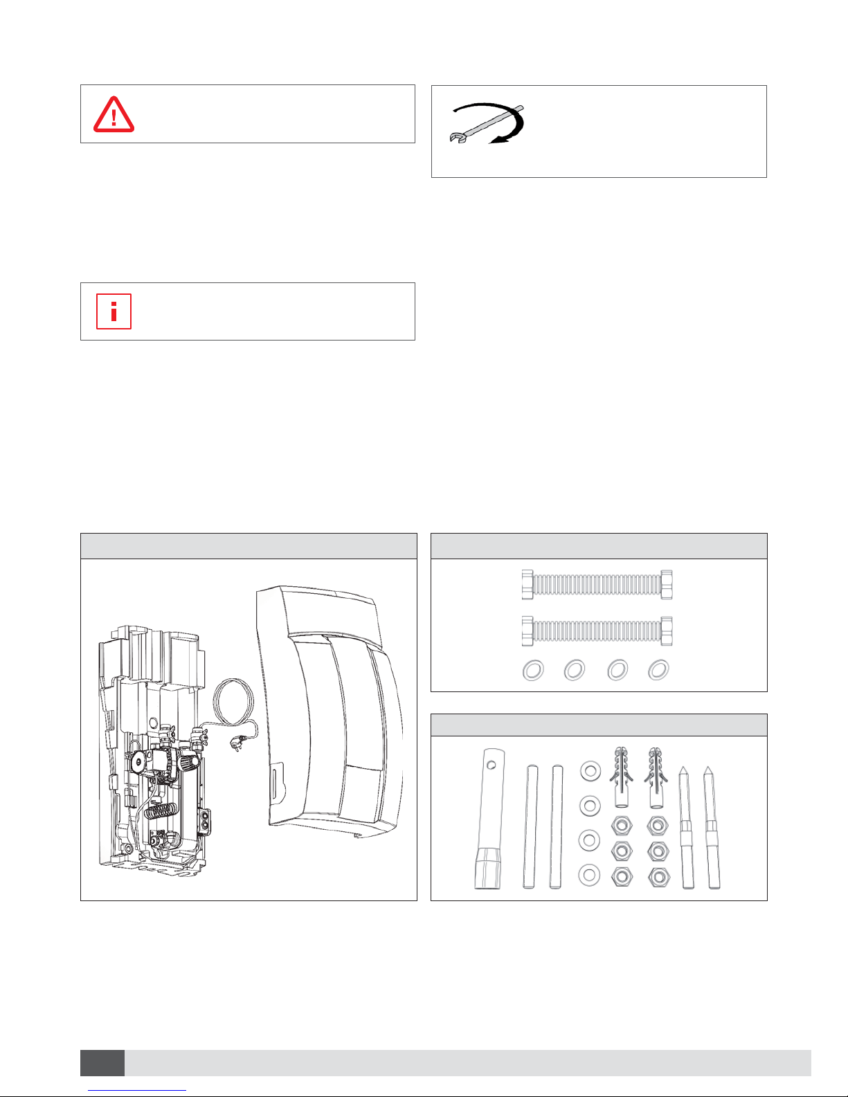
Scope of delivery3
Symbol legend2.2
Safety instructions
are marked with a warning triangle as
illustrated on the left.
Safety instructions indicate important information
for potentially dangerous situations for person
and device. Additional buzzwords describe nature
and severity of the danger.
Advices
are marked with an information sign
as illustrated on the left..
Advices highlight important information for situa-
tions without severe danger for person and de-
vice.
max. tightening
torque [Nm]
ti ht i
Screw wrench
indicates the maximum tighte-
ning torque and the rotational
direction.
Fresh Water Station
Fresh Water StationPicture 1:
Connection Set
Connection setPicture 2:
Mounting Set
Mounting setPicture 3:
5Provisions
E & OE, subject to change without notice.
Provisions4
Statutory provisions4.1
The Device must be installed and operated accor-
ding to the following norms and country specific
directives and provisions.
DIN EN 12828•
DIN 1988•
DIN 4708•
DIN 4753•
DIN 4757•
DIN 18380•
DIN 18381•
DIN 18382•
DIN EN 12975•
VDE 0100•
VDE 0185•
VDE 0190•
ÖNORM H5195•
Manufacturer’s specifications4.2
The stated values are guideline values which can
deviate under certain operating conditions.
Material damage
Deviations from the values stated in
table 1 may lead to damages and
functional limitations of the device.
Noncompliance with these values
leads inevitably to a loss of guarantee.
Material damage
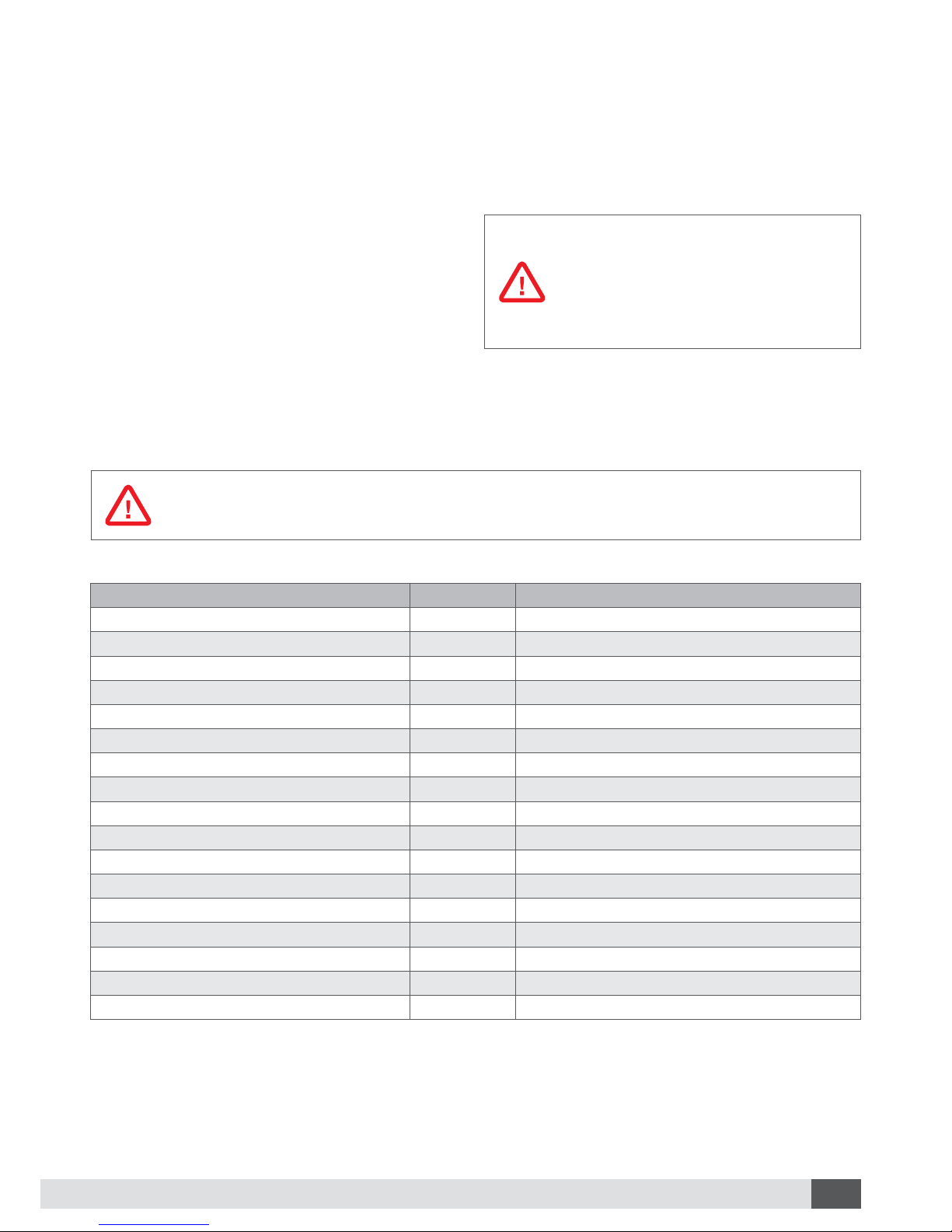
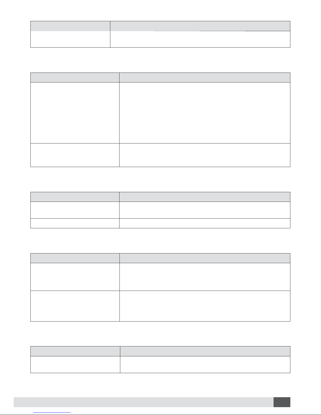
For operating the Fresh Water Station, the following specific values have to be adhered:
permissible dissolved matter and maximum values.Table 1:
Dissolved matter Unit Specific values (copper brazed)
pH-value 7-9 (considering Saturation index)
Saturation index (delta pH-value) -0,2 < 0 < +0,2
Degree of hardness °dH 6-15
conductivity μS/cm 10...500
Filterable matter mg/l <30
Free chlorine mg/l <0,5
Hydrosulfide (H2S) mg/l <0,05
Ammoniac (NH3/NH4+) mg/l <2
Sulfate mg/l <100
Hydrocarbonate mg/l <300
Hydrocarbonate/Sulfate mg/l >1,0
Sulfide mg/l <1
Nitrate mg/l <100
Nitrite mg/l <0,1
Iron, solute mg/l <0,2
manganese mg/l <0,1
Free aggressive carbonic acid mg/l <20
6Technical data E & OE, subject to change without notice.
Technical data5
8
7
5
4
3
2
1
6
B
C
AD
E
9
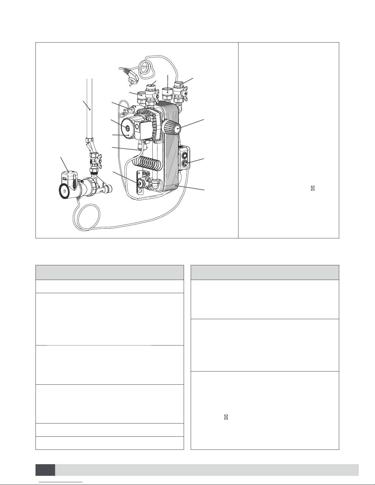
1 Thermostatic head
2 Electricity box
3 Plate heat exchanger
4 Flow-Switch
5 Charge pump
6 Coiled probe
7 Push-in connection for
circulation unit (incl.
blind cap)
8 Circulation unit (optional)
9 Bleed screw charge
pump
A Cold water
B Hot water
C From buffer tank ( ow)
D To buffer tank (return)
E Circulation pipe (not
included)
Design of Fresh Water StationPicture 4:
Fresh Water Station 20
Max. flow rate 20 l/min
Charge pump 230 V (50 Hz)
Rotation speed 2200 U/min
Power input 95 W
Nominal current 0,4 A
Circulation unit 230 V (50 Hz)
Power input 8 W
Nominal current < 0,1 A
Max. operating pressure
Tap water circuit 10 bar
Buffer water circuit 3 bar
PPEnoitalusnI
gk71thgieW
Fresh Water Station 30
Temperatures min. - max.
Ambiance 2°C - 40°C
Buffer water 2°C - 95°C
Dimensions
mm004htdiW
mm008thgieH
mm033htpeD
Connections
Cold water G1” internal thread
Hot water G1” internal thread
Buffer ow G1” external thread
Buffer return G1” external thread
Circulation G ½“ internal thread
Technical dataTable 2:
7Installation
E & OE, subject to change without notice.
Installation6
Material damage
Avoid tightening torque and force
effects on already installed parts and
connections of the device.
Regulation
The Fresh Water Station includes a
self-sufficient regulation. An additional
external regulation is not intended and
not allowed..
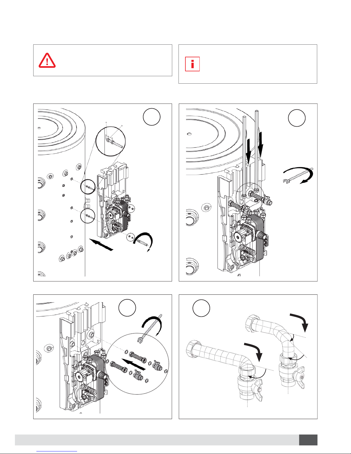
Installation on buffer tank6.1
1
10 mm 40 mm
max. 10 Nm
Installation of Fresh Water StationPicture 5:
3
max. 70 Nm
Installation of connection setPicture 6:
2
max. 70 Nm
Installation of water pipingPicture 7:
4
90°
90°
45°
Shaping of flexible hosesPicture 8:
0
N
m
m
max. 70 Nm
8Installation E & OE, subject to change without notice.
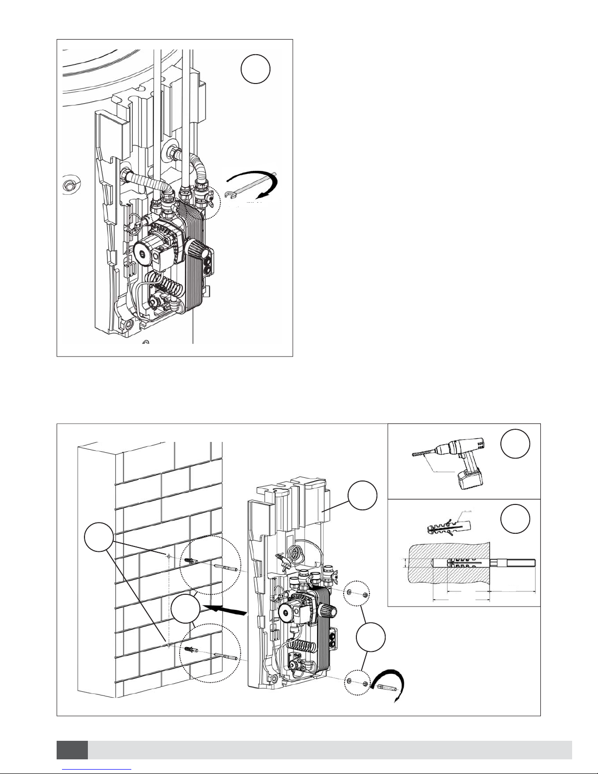
Wall fastening6.2
5
Final assembly of shaped connection setPicture 9:
1
2
1
2
3
Wall fasteningPicture 10:
max. 70 Nm
4
max. 10 Nm
60
min. 80
S12
12 mm
Ø12
max. 70 N
70 N
10 Nm
0N
9Installation
E & OE, subject to change without notice.
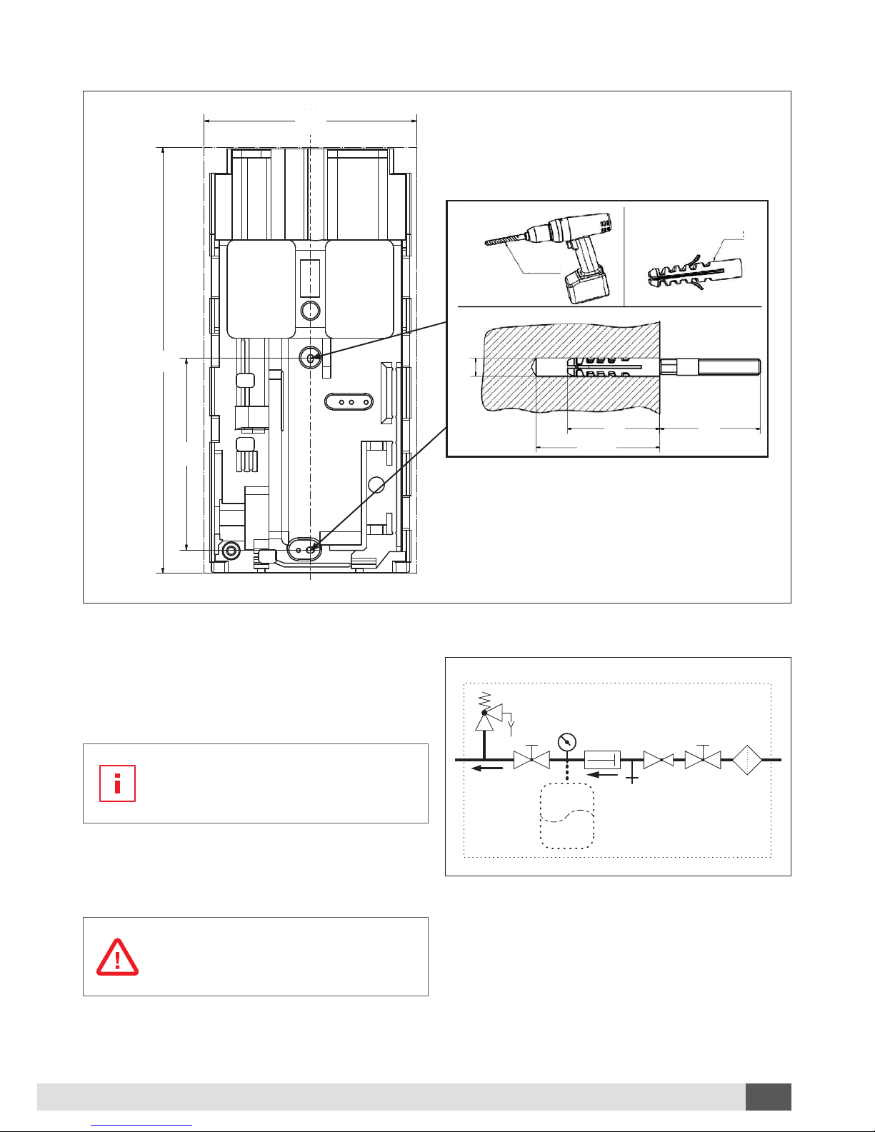
Hydraulic installation6.3
Install the hydraulic piping according to the in-
structions in chapter 6.1 or 6.2.
Piping
Piping between buffer tank and Fresh
Water Station ought to be as short as
possible.
When using different piping materials take care of
the installation sequence to avoid electrochemical
corrosion.
Personal and material damage
The tap water supply needs to be
constructed according to specification
(see picture 12).
Specification of tap water supplyPicture 12:
9
10
13
14
15
16
17
K
Expansion vessel (optional)
Manometer
Security valve (6bar)
Cut-off valve
Backflow preventer
Pressure reducer (necessary if K >= 6 bar)
Fine filter
Tap water main connection
9
13
14
10
15 16 14
K
800
400
359,5
Drilling plan for wall fastening
Drilling plan for wall fasteningPicture 11:
17
60
min. 80
S12
12 mm
400
800
395,5
Ø12

10 Installation E & OE, subject to change without notice.
Circulation unit (optional)6.4
This chapter is only relevant for Fresh
Water Stations with a circulation unit.
Design of circulation unit6.4.1
1
3
8
9
7
6
2
5
5
4
1 Circulation pump
2 Gasket ring
3 Plug-in adapter
4 Non-return valve
5 Flat gasket
6 Cut-off cock
7 Swivel nut
8 Eccentric tappet
9 Circulation pipe (not
included)
Circulation unitPicture 13:
11Installation
E & OE, subject to change without notice.
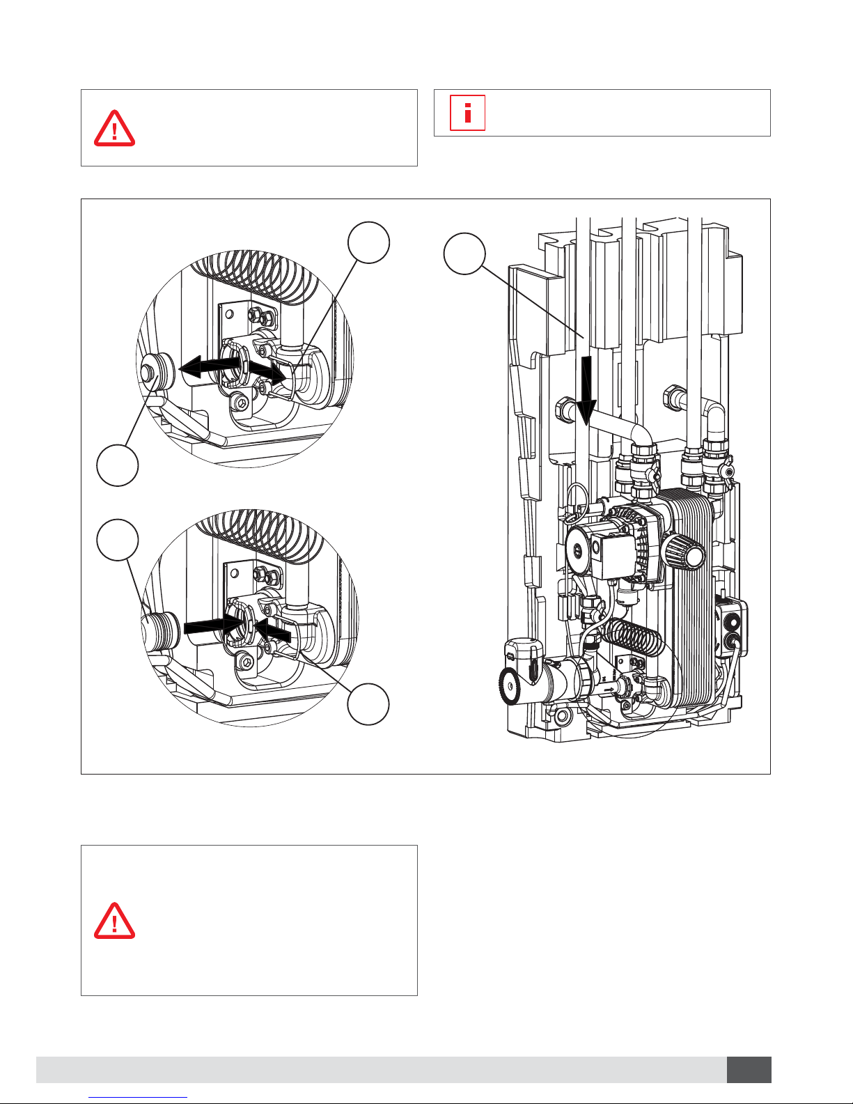
Installation of circulation unit6.4.2
Personal and material damage
Sufficient expansion and overpressure
safety devices must be installed in the
circulation circuit.
A rinsing port needs to be installed in
the circulation circuit.
1
2
3
4
5
Installation circulation unitPicture 14:
Electric connection of circulation unit6.4.3
Danger to life
Manipulation of electrical parts•
must be conducted by a profes-
sional electrician.
Deenergize the device before•
opening it.
Local regulations must be ob-•
served.
Connect the circulation unit according to the
desired operating mode. The connector assign-
ment for time-dependent circulation is depicted
in picture 16 and the connector assignment for
pulsed circulation is depicted in picture 17.

12 Installation E & OE, subject to change without notice.
A
B
C
Circulation unitPicture 15:
A
B
C
Temperature dial
Timer clock with switching segments
Operation mode selector
Circulation shutdown temperature►
The circulation will be deactivated when the shut-
down temperature is reached.
The preset temperature at the tem-
perature dial (A) must be at least 10
K below the set temperature at the
Fresh Water Station to avoid non-stop
operation of the circulation unit.
Set the temperature dial to the desired tempera-
ture.
Manual deactivation of circulation unit►
Set operation mode selector ( C ) to “OFF”.
Time-dependent circulation (factory pre-►
setting)
Set the switching times of the circulation unit with
on the timer clock (B)
Set operation mode selector (C) to “TIMER”.
Timer clock switching segments (B) Circulation unit status
Up
Down
Activated
Deactivated
NLNL
HT-PUMP 230V IN
NLL2
FLS CIRC PUMP
M
~
M
~
2
1
3
5
4
Connector assignment time-dependent circulationPicture 16:
1
2
3
4
5
Flow-Switch (FLS)
Charge pump Fresh Water Station (HT PUMP)
Circulation pump (CIRC PUMP)
Connection clamp
Power supply (230 V / 50 Hz)
Pulsed circulation►
The circulation unit is activated by a short actuati-
on of a hot water tapping point.
Set operation mode selector (C ) to “ON”.
NLNL
HT-PUMP 230V IN
NLL2
FLS CIRC PUMP
M
~
M
~
2
1
3
5
4
Connector assignment pulsed circulationPicture 17:
1
2
3
4
5
Flow-Switch (FLS)
Charge pump Fresh Water Station (HT PUMP)
Circulation pump (CIRC PUMP)
Connection clamp
Power supply (230 V / 50 Hz)
Operating modes of circulation unit6.4.4

13Initiation
E & OE, subject to change without notice.
Initiation7
Material damages
Put Fresh Water Station into operation
only after completed filling.
Check tightness of swivel nuts.•
Fill device and check for leak-tightness.•
Open valves on both buffer and tap water•
sides slowly to avoid pressure blows.
Connect device to power supply.•
De-aeration and rinsing of device:•
Open a nearby hot water tapping point and»
turn thermostatic head to maximum.
The buffer-side is de-aerated with the»
charge pump bleed screw (see picture 4).
Continue the process until the system is
completely de-aerated.
Stream noises
in the charge pump are an indication
of air in the system.
Set the hot water temperature as desired by•
turning the thermostatic head.
Set circulation unit (optional)•
Clip on insulation.•
After initiation the complete system needs to be
checked for function and leak-tightness.

14 Malfunctions E & OE, subject to change without notice.
Malfunctions8
Prior to malfunction diagnostics, make sure
that the following parameters are met:
Sufficient flow temperature, minimum 55°C at►
maximum 45°C tap water temperature.
Faultless electrical connection.►
Personal and material damage
Execute fault repair only with ade-►
quate qualification.
Disconnect the device from power►
supply before opening it.
Adhere to regional norms and►
regulations!
No hot water8.1
Cause Relief
Buffer tank not hot enough Increase temperature in buffer tank►
Charge pump doesn’t
convey buffer water
Check water level in buffer tank (extraction of buffer water for the►
Fresh Water Station happens at the highest point of the tank).
De-aerate buffer circuit and check system pressure.►
Check, if all shutoffs (buffer and tap water side) are open. If not,►
open them.
Check hydraulic resistance between buffer tank and Fresh Water►
Station and reduce it, if necessary.
Check at initiation if the Fresh Water Station is correctly con-►
nected to the buffer circuit and drinking water system.
Check Flow-Switch and electricity box.►
Replace broken charge pump.►
Flow-Switch sends no signal
to charge pump
Remove Flow-SwitchA
Clean Flow-Switch housingB
Reintegrate Flow-SwitchC
If the Flow-Switch still sends no signal to the charge pump,D
replace Flow-Switch.
Electricity box broken
(relay doesn’t switch)
Check if power cord is connected to the electricity network.A
Close shutoff valvesB
Remove Flow-SwitchC
Activate Flow-Switch manually. A working relay causes a swit-D
ching noise in the electricity box.
If there is no switching noise, replace electricity box.E
Wrong hot tapping water
temperature
Tap hot water. Turn the thermostatic head to max. temperatureA
for a short time.
Hot water is prepared: set then thermostatic head to the desired►
temperature.
No hot water is prepared:►
Check buffer water temperature.»
Check the heat exchanger for thermal furring.»
15Malfunctions
E & OE, subject to change without notice.
Cause Relief
Thermal furring of plate heat
exchanger
Clean plate heat exchanger►
No circulation8.2
Cause Relief
Circulation pump doesn’t
convey.
Check if shutoff at circulation connection is open.►
Check electric connections.►
Circulation pump is not set properly. To check that, set the►
operation mode selector to “ON”
If the pump conveys water, check settings on the pump»
and eventually switch to “Timer Mode”
If no water is conveyed, replace circulation pump.»
Hydraulic resistance of tap
water piping is too big for circu-
lation pump
Check dimensioning of tap water piping.►
No/wrong switching times8.3
Cause Relief
Circulation unit was switched to
time-independent circulation
Reconnect wiring of circulation pump for time-dependent►
circulation
Timer clock misaligned Set timer clock and switching times►
Constant circulation mode8.4
Cause Relief
Circulation unit is not set
properly
Check settings of circulation pump►
Set timer clock»
Set operation mode selector to desired mode»
Set temperature on circulation
unit is higher than the set tem-
perature on the thermostatic
head
Align the temperature setting of the circulation unit (approxi-►
mately 10°C below the set tap water temperature)
Fresh Water Station leaks8.5
Cause Relief
Fresh Water Station is leaking Check connection of pipes and sealings at the leaking de-►
vice. Replace broken sealings.

16 Terms of warranty E & OE, subject to change without notice.
Terms of warranty9
The Manufacturer issues a warranty of two years
from the invoice date on the device and its consti-
tuent parts.
Without proper installation and use of the device
the warranty is void.
17Appendix
E & OE, subject to change without notice.
Appendix10
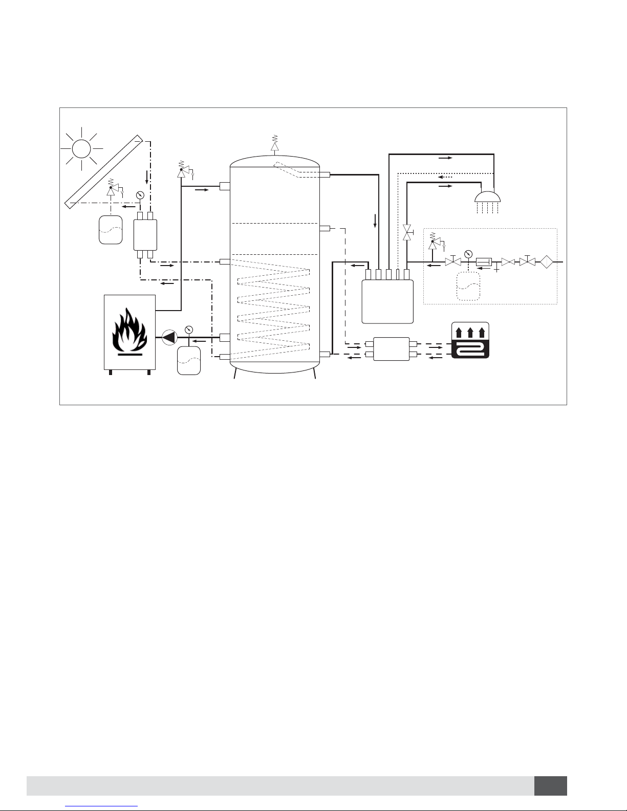
Example of use10.1
1
2
3
4
5
6
7
8
9
10
11
12
13
14
15
16
17
18
19
Buffer tank
Fresh Water Station
Tapping point
Heating boiler
Solarstation
Solar collector
Heating Circuit group
Heating circuit
Expansion vessel
Manometer
Buffer charge pump (heating boiler)
Bleeder
Security valve
Shutoff valve
Backflow preventer
Pressure-reducing valve
Fine filter
Bare tube-heat exchanger
Layer separating plate
A
B
C
D
E
F
G
H
I
J
K
Heating boiler flow
Solar flow
Heating boiler return
Solar return
Buffer water flow
Heating circuit flow
Buffer water/heating circuit return
Tap water (hot)
Circulation return (optional)
Tap water (cold)
Tap water supply
Example of usePicture 18:
1
2
3
4
7
8
5
9
9
9
6
18
11
12
13
13
13
14
14 10 15 16 14
10
I
10
H
J
A
C
DG
F
E
B
19
19 K
17
18 Appendix E & OE, subject to change without notice.
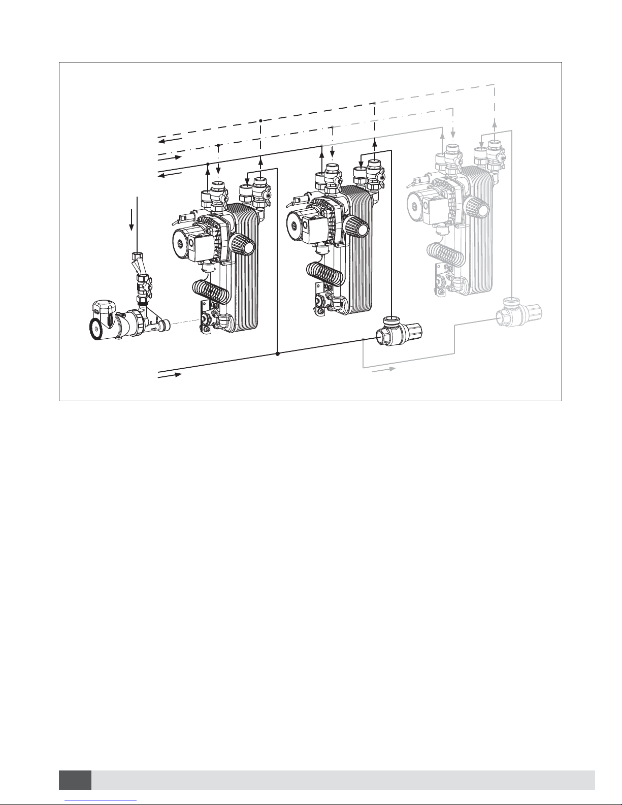
Cascade connection10.2
4
1
2
3
5
5
A
B
C
E
D
25 kPa
35 kPa
Cascade connectionPicture 19:
1
2
3
4
5
Fresh Water Station – Station 1
Fresh Water Station – Station 2
Fresh Water Station – Station 3
(max. 3 stations)
Circulation unit (optional)
Overflow valve
A
B
C
D
E
Buffer water return
Buffer water flow
Tap water (hot)
Circulation return (optional)
Tap water supply

19Appendix
E & OE, subject to change without notice.
Notes:

700369-1201-en
Contact
SEG Solar Energy GmbH
Hauptplatz 7
A-9300 St.Veit/Glan
www.solarsales.eu
Table of contents
Popular Water Dispenser manuals by other brands

IBC Water
IBC Water AST0715MP-960 Installation & operating instructions

Lancaster Water Treatment
Lancaster Water Treatment X FACTOR LX15 Series Installation, operating and service manual

Elkay
Elkay EMABF8 Series Installation & use manual

Oasis
Oasis Osmosis Home installation manual

Monarch Water
Monarch Water ULTIMATE MINI AQUA HE install guide

Haier
Haier HLM-109B instruction manual


