Solar Frontier PowerSet Turbo Series User manual

ENGLISHDEUTSCHITALIANONEDERLANDS
Solar Frontier Europe GmbH
Installation and Operating Manual
PowerSet Turbo and PowerSet Mini
Installations- und Bedienungsanleitung
PowerSet Turbo und PowerSet Mini
Manuale di installazione e funzionamento
PowerSet Turbo e PowerSet Mini
Installatie- en bedieningshandleiding
PowerSet Turbo en PowerSet Mini

1
Contents
1. General Safety Advice 2
1.1 Safety advice for Solar Frontier SF165-S/SF170-S photovoltaic modules 2
1.2 Safety advice for Turbo inverters 2
2. Proper usage 2
3. Components included and structure of the PowerSet 2
4. About this Manual 3
4.1 Contents 3
4.2 Target audience 3
4.3 Markings 3
4.3.1 Symbols 3
4.3.2 Keywords 3
4.3.3 Markings used in the text 3
4.3.4 Abbreviations 4
5. Installation 4
5.1 Mounting system / substructure 4
5.2 Mechanical installation of Solar Frontier SF165-S/SF170-S
photovoltaic modules 4
5.2.1 Site location 4
5.2.2 Handling instructions 4
5.2.3 Mounting instructions 4
5.3 Electrical installation photovoltaic generator 6
5.3.1 Electrical wiring safety precautions 6
5.3.2 Cabling 6
5.3.3 Grounding 7
5.3.4 Electrical wiring 7
5.4 Installation of Turbo inverters 8
5.4.1 Safety measures during installation 8
5.4.2 Mounting the inverter 8
5.4.3 Preparing the AC connections 8
5.4.4 Preparing the DC connections 9
5.4.5 Prepare the data connection cable required for
using Power Monitoring 9
5.4.6 Connecting a PowerStorage system 9
5.4.7 Modbus RTU data connection cable for connecting an
energy meter 9
5.4.8 Connecting the inverter and switching on the AC power 9
5.4.9 Initial commissioning of the inverter 9
5.4.10 Switching on the DC supply 11
5.4.11 Feed-in management or PowerStorage 11
5.4.12 Registration and configuring PowerMonitoring 11
5.4.13 De-installing the inverter 11
6. Structure and function of the Turbo inverter 12
6.1 Casing 12
6.2 Operating buttons 12
6.3 Overview of operating functions 13
6.4 Service menu 13
6.5 Troubleshooting 14
7. Maintenance 16
7.1 Maintenance of Solar Frontier SF165-S/SF170-S photovoltaic modules 16
7.2 Maintenance DC system 16
7.3 Maintenance of Turbo inverters 16
8. Transport and Storage 16
9. Disposal 16
9.1 Disposal within the EU 16
9.2 Disposal outside the EU 16
10. Technical data and data sheets 16
10.1 Solar Frontier SF165-S/SF170-S photovoltaic modules
16
10.2 Technical data for Turbo inverter 18
10.3 Technical data AC cable and line circuit breakers 19
10.4 Table of countries 19
10.5 Plugs, sockets, DC cable and Y-cable 22
10.5.1 Product information for plug and socket 22
10.5.2 Product information for DC cable / minimum requirements 22
10.5.3 Product information Y-cable 22
11. Exclusion of Liability 22
12. Contact 22
13. Appendices 23
13.1 AC plug for Turbo inverters 23
13.2 SunClix connectors 26
2
ENGLISH
1. General Safety Advice
Please ensure all necessary measures are taken to prevent accidents. The use of
PowerSets in applications that may endanger human lives is prohibited, including
in air and road transport systems.
PowerSets must not be used for anything other than their expressed purpose.
Solar Frontier strongly advises you to follow the instructions below in order to
avoid bodily injury, damage to property and/or death.
PowerSets sold by Solar Frontier GmbH may only be installed by authorized
professionals (see 4.2). As soon as it becomes evident that safe operation is
no longer possible (e.g., visible damage), remove the PowerSet immediately
from the grid.
1.1 Safety advice for Solar Frontier SF165-S/SF170-S
photovoltaic modules
•Installation, wiring and maintenance of SF modules must only be carried out
by licensed and trained persons.
•Ensure that all instructions and warnings related to SF modules and all instruc-
tions from the manufacturer of the system components are fully understood
prior to installing and operating a PV solar system.
•The front surface of SF modules should be covered with an opaque material
during installation to decrease the potential of electrical shock.
•SF modules only generate direct current (DC) electricity.
•SF modules do not have the ability to store electricity.
•SF modules will experience higher voltage when connected in series and
higher electrical current when connected in parallel.
•Only interconnect SF modules with similar electrical characteristics in series or
in parallel to prevent system imbalance conditions and module damage.
•The PV array open circuit voltage must never exceed the maximum system voltage
(including in low temperature conditions)
.
•Excessive leakage currents are a shock and fire hazard.
•Under no circumstances disconnect the cable from operational modules or
electrical arcing may occur. This may result in serious bodily harm or death.
•Do not use SF modules for purposes other than terrestrial power generation to
prevent electrical shock, fire and other accidents.
•Do not artificially concentrate sunlight on modules using lenses or mirrors.
•Do not use light sources other than natural sunlight and general illumination for
power generation.
•Do not use SF modules in water or liquid. Contact with water or other liquid signifi-
cantly increases the risk of electric shock.
•The level of leakage current must be limited in accordance with local regula-
tions for safety reasons.
•Carefully check the polarity of the connections before installing. Incorrect wir-
ing may damage SF modules or appliances.
•Only use tools, plugs, cables and support structures suitable for solar electric
systems.
•Wear appropriate protective clothing when working on SF modules and take
all necessary precautions to prevent electric shock, especially when DC voltage
exceeds 30 V.
1.2 Safety advice for Turbo inverters
•Install and use the device only after reading and understanding this document.
•Always perform the measures described in this document in the sequence
specified.
•Keep this document in a safe place for the entire service life of the device. Pass the
document on to subsequent owners and operators of the device.
•Improper operation can reduce the yields of the photovoltaic system.
•The device must not be connected to the DC or AC cables if it has a damaged
casing.
•Switch the device off immediately and disconnect it from the grid and the
solar modules if any of the following components is damaged:
- Device (not functioning, visible damage, smoke emission, penetration by
liquid, etc.)
- Cables
- Solar modules
•The system must not be switched back on until
- the device has been repaired by the dealer or manufacturer.
- damaged cables or solar modules have been repaired by a technical
professional.
•Never cover the Device.
•Do not open the casing. Danger! This will void the warranty!
•Factory labels and markings must never be altered, removed or rendered
unreadable.
•Observe the respective manufacturer‘s manual when connecting an external
device that is not described in this document (e.g., external data logger). Incor-
rectly connected components can damage the inverter.
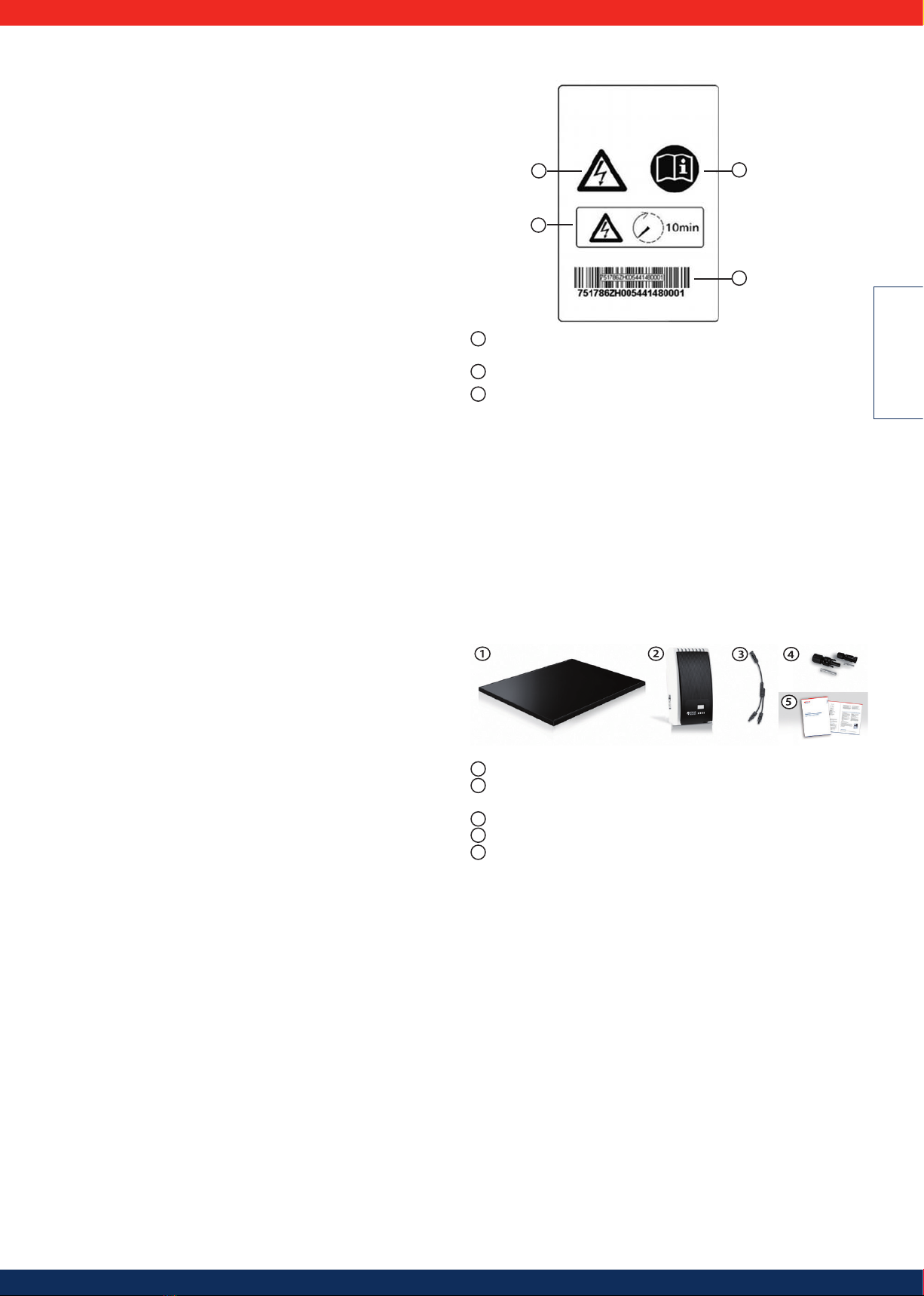
Safety advice for the device:
Figure 1
2
3
1
1
1Dangerous voltages can remain present on the components up to 10 minutes
after switching off the DC circuit breaker and the line circuit breaker.
2Read and follow the instructions!
3Serial number as a bar code and in plain text
2. Proper usage
The PowerSet may only be used in grid-connected photovoltaic systems. The
modules, inverter, cables, and connectors have been mutually calibrated for best
performance. The connections may not be grounded.
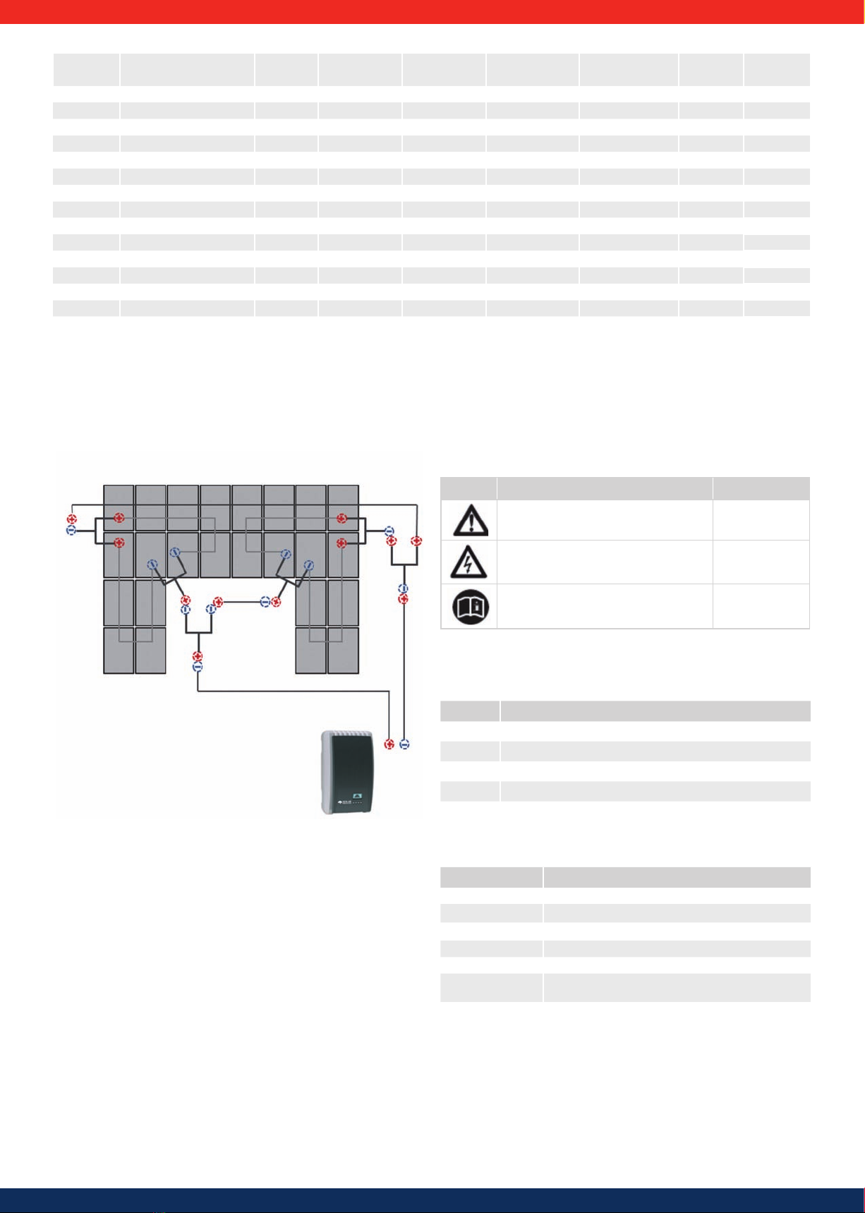
3. Components included and structure of the
PowerSet
The Solar Frontier PowerSet comprises the following components. The number of
components required can be determined using the list below based on the type
of PowerSet you have:
1Solar Frontier SF165-S/SF170-S photovoltaic module
2Solar Frontier Turbo 1P Mini / 1P / 3P1 / 3P2 inverter (incl. inverter, mounting
plate, 1 pair SunClix connectors and AC plug)
3
Y-cables, Version for (+) and (-)
4DC plugs and DC sockets (3 of each in one pack)
5Installation and maintenance manual
3
Area PowerSet Description Capacity Modules Inverters Grid connection Y- cables
Plugs &
sockets
Modules
in series
15.6 m² PowerSet Mini 2.0-170-1p 2.04 kWp 12 x SF170-S 1 x Turbo 1P Mini 1ph 3 (+) & 3 (-) 3 + 3 3
18.2 m² PowerSet Turbo 2.4-170-1p 2.38 kWp 14 x SF170-S 1 x Turbo 1P 1ph 1 (+) & 1 (-) 3 + 3 7
23.4 m² PowerSet Turbo 3.0-165-1p 2.97 kWp 18 x SF165-S 1 x Turbo 1P 1ph 2 (+) & 2 (-) 3 + 3 6
23.4 m² PowerSet Turbo 3.1-170-1p 3.06 kWp 18 x SF170-S 1 x Turbo 1P 1ph 2 (+) & 2 (-) 3 + 3 6
23.4 m² PowerSet Turbo 3.1-170-3p 3.06 kWp 18 x SF170-S 1 x Turbo 3P1 3ph 2 (+) & 2 (-) 3 + 3 6
26.0 m² PowerSet Turbo 3.4-170-1p 3.40 kWp 20 x SF170-S 1 x Turbo 1P 1ph 3 (+) & 3 (-) 3 + 3 5
27.3 m² PowerSet Turbo 3.6-170-1p 3.57 kWp 21 x SF170-S 1 x Turbo 1P 1ph 2 (+) & 2 (-) 3 + 3 7
31.2 m² PowerSet Turbo 4.0-165-1p 3.96 kWp 24 x SF165-S 1 x Turbo 1P 1ph 3 (+) & 3 (-) 3 + 3 6
31.2 m² PowerSet Turbo 4.1-170-1p 4.08 kWp 24 x SF170-S 1 x Turbo 1P 1ph 3 (+) & 3 (-) 3 + 3 6
31.2 m² PowerSet Turbo 4.1-170-3p 4.08 kWp 24 x SF170-S 1 x Turbo 3P1 3ph 3 (+) & 3 (-) 3 + 3 6
36.4 m² PowerSet Turbo 4.8-170-1p 4.76 kWp 28 x SF170-S 1 x Turbo 1P 1ph 3 (+) & 3 (-) 3 + 3 7
39.0 m² PowerSet Turbo 5.1-170-3p 5.10 kWp 30 x SF170-S 1 x Turbo 3P2 3ph 4 (+) & 4 (-) 6 + 6 6
45.5 m² PowerSet Turbo 6.0-170-3p 5.95 kWp 35 x SF170-S 1 x Turbo 3P2 3ph 4 (+) & 4 (-) 6 + 6 7
54.6 m² PowerSet Turbo 7.1-170-3p 7.14 kWp 42 x SF170-S 1 x Turbo 3P2 3ph 5 (+) & 5 (-) 6 + 6 7
62.4 m² PowerSet Turbo 8.2-170-1p 8.16 kWp 48 x SF170-S 2 x Turbo 1P 1ph 6 (+) & 6 (-) 6 + 6 6
Accessories congured for the PowerSets are separately available from Solar Frontier: DC cables, mounting and fastening material, tools for assembly of the cables...
Schematic structure based on
PowerSet Turbo 3.1
example
Inverter
DC-Cable with plug and socket
Y-Cable
PV Generator
Figure 2
4. About this Manual
4.1 Contents
These instructions contain all information required by a technical professional for
setting up and operating the inverters.
When installing other components (e.g., AC cable, mounting system) follow the
manufacturer's instructions.
4.2 Target audience
Unless otherwise indicated, the target audiences of this manual are technical
professionals and system operators.
Technical professionals are persons who, for example:
•have the knowledge of terminology and the skills necessary for setting up and
operating photovoltaic systems;
•because of their professional training, knowledge and experience and knowl-
edge of the relevant regulations can assess the following tasks and recognise
possible dangers:
- mounting electrical devices
- assembling and connecting data cables
- assembling and connecting power supply cables.
4.3 Markings
4.3.1 Symbols
Symbol Description Location
General danger warning Manual
Danger from electricity Manual / device
Read manual before using the product. Device
4.3.2 Keywords
Keywords used in conjunction with the symbols described above:
Keyword Description
Danger Immediate danger of death or serious bodily injury
Warning Possible danger of death or serious bodily injury
Caution
Possible danger of light or medium bodily injury
Attention Possible damage to property
Advice Tips on operation or usage of the manual
4.3.3 Markings used in the text
Markings Description
√ Condition for action
Single step
1., 2., 3., ... Several steps in series
cursive light emphasis
bold strong emphasis
Courier Designation of product elements such as buttons.,
displays, operating state

4
ENGLISH
4.3.4 Abbreviations
Abbreviation
Description
ACurrent in amperes
AC Alternating current voltage
DC Direct current a
Derating Power reduction
DHCP The use of DHCP allows automatic integration of the device into
an existing network (Dynamic Host Configuration Protocol)
MSD Internal mains monitoring for the inverter (mains monitoring
units with allocated all-pole switching devices).
RC Residual current
ICurrent
lkShort circuit current
Impp Current at maximum power point
kVA Kilovoltampere
kW Kilowatt
kWh Kilowatt-hour(s)
mMetre
m2Square metre
MPP Operating point with the highest output (maximum power point)
MPP tra
cker
Controls the power of the connected module strings to match the
MPP
Nm Newton metre
PElectrical power
Pa Pascal
PV Photovoltaic
SELV, TBTS,
MBTS Schutzkleinspannung (EN: safety extra low voltage; FR: Très Basse
Tension de Sécurité; ES: Muy Baja Tensión de Seguridad)
SF Solar Frontier
STC Standard test conditions
UVoltage
ULOpen circuit voltage
Umpp Voltage at maximum power point
UPV
The generator voltage present at the DC connection (photovol-
taic voltage)
VVolt
W/m2Watt per square metre
ηEfficiency
5. Installation
Compliance with all relevant national and local laws, regulations and di-
rectives, especially for accident avoidance, as well as all relevant technical
standards is mandatory for a safe installation.
5.1 Mounting system / substructure
The PowerSets are delivered in standard form without an assembly system. Solar
Frontier offers a suitable assembly system as a separate accessory. For more infor-
mation, see: www.solar-frontier.eu. In general, all commonly available mounting
systems which ensure proper mounting following the guidelines in point 5.2.3 are
suitable. Your installer will be able to suggest an appropriate solution.
5.2 Mechanical installation of Solar Frontier SF165-S/
SF170-S photovoltaic modules
5.2.1 Site location
•Ensure that the maximum wind and snow loads in local conditions do not
exceed the SF module maximum load ratings.
•Avoid installing SF modules in areas where they are exposed to oil vapour and/
or corrosive gas.
•Avoid accumulation of grit or dust on the SF modules as it may reduce the
output yield.
•Do not expose SF modules to sulphurous atmospheres.
•Do not install SF modules in locations where flammable gases accumulate or
flow as there is a risk of sparks from SF PV modules.
•Do not install SF modules near fire.
•Avoid installing SF modules in locations where they may be covered by perma-
nent shadows.This may adversely affect their performance.
•Do not install SF modules in locations where temperatures exceed the tem-
perature range indicated in the module’s technical specifications.
5.2.2 Handling instructions
•Do not disassemble or modify SF modules. This may result in an electric shock,
fire or other accidents. Solar Frontier cannot be held responsible for any loss or
damage caused by unauthorized disassembling, modification or misuse of SF
modules.
•Do not drill additional mounting holes into the aluminium frame. Only pre-
drilled holes should be used.
•Avoid placing any stress onto the SF modules, cables or connectors.
(Minimum bending radius of 39 mm (1.54 in) for module cables is recom-
mended)
•Do not stand or step on SF modules. This may result in damage to the module
and/or bodily harm by falling.
•Do not drop SF modules or drop objects onto them. Both sides of the module
(the glass surface and the back sheet) are fragile.
•Do not strike the terminal box or pull the cables. The terminal box can crack
and break, while the output cable may unplug and cause electricity leakage or
an electric shock.
•Do not scratch the back sheet or cables of the SF modules. Rubbing or scratch-
ing may result in an electric shock, electric leakage or an accident.
•Do not scratch the insulation coating of the frame (except for the grounding
connection). This may weaken the strength of the frame or cause corrosion.
•Do not cover the water drain holes of the frame. Doing so may cause frost
damage.
•Do not use glue when closing the cover of the junction box. Similarly, do not
use a sealant to bond the junction box lid to its base.
5.2.3 Mounting instructions
Mounting structures cautions
• Pay attention to the electrochemical series when selecting support structure
material to avoid galvanic corrosion.
• Fasten and lock bolts completely. Inadequate mounting may result in SF mod-
ules falling or other accidents.
• Make sure that SF modules have been connected securely to the substructure.
The substructure should consist of durable, rustproof. UV resistant material.
Please adhere to national regulations.
• Ensure that your mounting support structure is designed to withstand the
SF module design snow and wind loads applicable for the chosen site. Solar
Frontier will not be responsible if the SF modules are damaged due to the
durability of the mounting support structure. Please consult your mounting
structure manufacturer.
Mounting the solar modules
• PV modules should typically face south in the Northern Hemisphere and north
in the Southern Hemisphere for optimum power production.
• Modules can be installed horizontally (landscape) or vertically (portrait).
• Maintain a space between SF modules and the roof. This will allow air to circu-
late, cooling the module, and allow condensation to dissipate. Solar Frontier
recommends a distance of at least 100 mm (3.94 in).
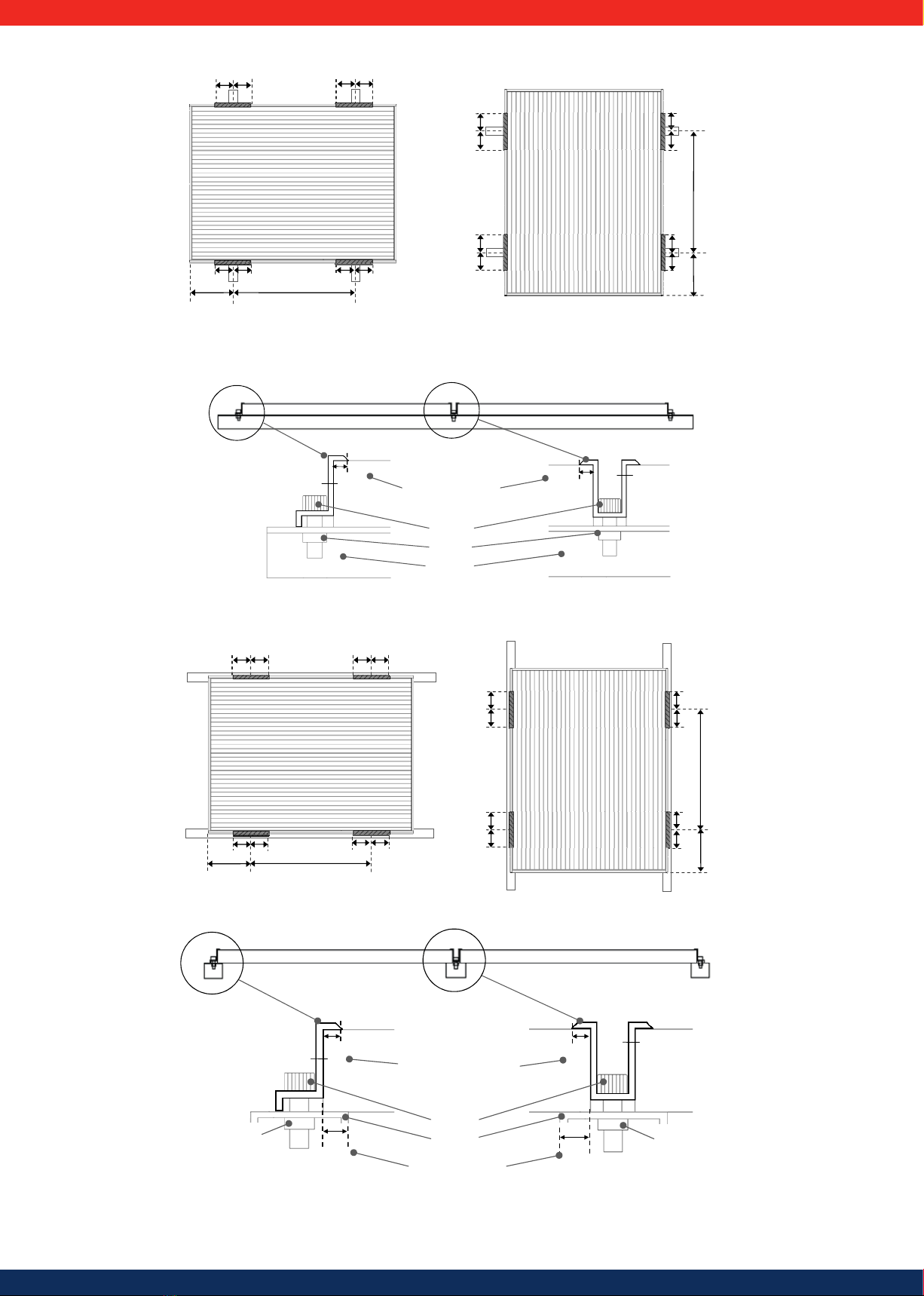
Mounting with clamps
Four or more corrosion-proof clamps should be used to fasten the SF modules to
the support structure securely. The clamps should be secured within the indicated
clamping zones (256 mm +/- 75 mm (10.08 in +/- 2.95 in) from the corners of the
long side of the module) using stainless steel M8 bolts with a minimum length of
20 mm (0.79 in).
All clamps must be at least 30 mm (1.18 in) long and 3 mm (0.12 in) thick and
overlap the module frame by 8 mm (0.31 in) or more.
Clamps must not create shadow nor cover the front glass, and shall not deform
the module frames during installation. For further instructions please contact the
clamp manufacturer.
Maximum load: 2.400 Pa (50 lbs/ft2) to the front and back of the module
5
Module perpendicular to support rails
Landscape (horizontal) Portrait (vertical)
256 mm 745 mm
75 mm 75 mm (2.95 in) 75 mm 75 mm (2.95 in)
75 mm 75 mm (2.95 in) 75 mm 75 mm (2.95 in)
75
mm
75
mm
75
mm
75
mm
75
mm
75
mm
7
4
5
mm
25
6
mm
75
mm
75
mm
(2.95 in)(2.95 in)
(2.95 in)
(2.95 in)
(10.08 in)
(10.08 in) (29.33 in)
(29.33 in)
Figure 3
Cross section of an array
Array Installation (section)
ape (
End clamp Middle clamp
Module
support rail
Bolt
Module Module
Nut
Module Module
Module
Clamp to module overlap
min 8 mm (0.31in)
8mm 8 mm 3 mm
3 mm
(10 0
(29.
(0.31 in) (0.31 in)
(0.12 in) (0.12 in)
Figure 4
Module parallel to support rails
256 mm
75 mm
745 mm
75 mm (2.95 in)
75 mm 75 mm (2.95 in) 75 mm (2.95 in)
75 mm
75 mm (2.95 in)75 mm
75 mm (2.95 in)75 mm
745 mm
256 mm
75 mm 75 mm (2.95 in) 75 mm (2.95 in)75 mm
75 mm 75 mm (2.95 in)
(10.08 in)
(10.08 in)
(29.33 in)
(29.33 in) Figure 5
Cross section of an array
Ar
L
Middle clamp
Module
support rail
Bolt
End clamp
Module Module Module
Module Module
Module to rail overlap,
min 10 mm (0.39 in)
10 mm
(0.39 in)
10 mm
(0.39 in)
Nut Nut
8 mm (0.31 in)
Clamp to module overlap,
min 8 mm (0,31 in)
8 mm (0.31 in) 3 mm (0.12 in)
3 mm (0.12 in)
95 in)
75
Figure 6
For alternative mounting methods please consult Solar Frontier.

6
ENGLISH
5.3 Electrical installation photovoltaic generator
5.3.1 Electrical wiring safety precautions
• The sum of Voc of modules in series must not exceed the maximum system volt-
age of the module under any condition. Reverse current applied to the modules
must not exceed 7 A
.
• Do not touch or handle the PV module, terminal box or the end of output
cables with bare hands.
• Do not carry out installation when PV modules, installation tools or installation
area are exposed to water.
• Ensure that the connection parts between SF modules and power receiving
devices are isolated and waterproof. Using SF modules with insufficient isola-
tion and waterproofing could result in an electric shock, an electric leak or an
accident.
• Keep the junction box and connecting cables away from any liquids until the
connectors are mated. Failure to do this may cause faulty wiring.
• The connecting components between the modules must be compatible
with the connecting system. They must enable them to work perfectly and
completely safely.
• Inverters must meet the technical requirements of SF modules.
• Do not connect the PV modules directly to loads such as motors. Variation in
output power may damage the motor.
• Observe and understand the safety instructions of batteries. Their misuse can
result in serious bodily harm due to high electrical current.
• Cables should be adequately protected from damage by wildlife.
5.3.2 Cabling
Solar Frontier places great value on delivering as many components as possible
pre-assembled in order to help avoid sources of error.
As each roof and PV installation has its own peculiarities, certain cables have to be
adapted on site to the system and assembled accordingly. For example, the cables
for extending the connecting cables to reach the inverter have to be assembled
on site. In addition, if there are obstructions on the roof (e.g. dormers) it may be
necessary to bridge the increased distance with extension cables. The DC cable,
sockets and plugs which are included in the PowerSet are for this purpose.
An Hosiden crimping tool (HSC2009-530030) is also required for crimping the
contacts. This is not included in the PowerSet. Pre-assembled connecting cables
must not be altered.
Please ensure a clean and proper assembly of the cables to avoid error
sources and to ensure safe cabling.
The DC cables used must comply with the requirements specified in Section 10.5.2
and be compatible with the plug-in connectors provided by Solar Frontier. Solar
Frontier recommends the use of the DC cables as specified in Section 10.5.2. These
are available from Solar Frontier.
The following tools are required to assemble the cables:
- Mounting key (not included in the delivery)
- Crimping tool for twisted contacts (not included in the delivery)
- Insulation stripping pliers (not included in the delivery)
Shortening and stripping the insulation from the DC cable
First, the cable has to be shortened to the proper length. Then the outer insulation
is removed with suitable insulation stripping pliers to a length of 6.5-7.5 mm.
Please take care not to damage the wires in the DC cable. This could reduce
the cross section and cause electrical faults.
Figure 7
Positioning
aid
Adjust the tool:
1. Lift the positioning aid
2. Turn the positioning aid by
±120° in the desired direction
Figure 8
Crimping the twisted contacts
The HSC2010 positioning aid is
used for crimping the pins.
Positioning aid HSC2013 is used for
crimping the contacts.
Figure 9
Crimping
pliers
Place the contact or pin in the posi-
tion for the respective cross-section.
Figure 10
Place the crimping sleeve com-
pletely into the tool as shown in
Figure 11.
Figu re 11
Do not close the crimping pliers
completely at first.
Close the tool gently and check
whether the crimping sleeve is
properly positioned in the crimping
die.
Figure 12
Guide the stripped end of the cable
fully into the crimping sleeve.
Then close the tool completely
while holding the cable until the
locking device has been triggered.
Figure 13
Check the crimping result and the
correct fit of all cable strands.
Figure 14
Connector Contact
Guide the crimped contact into the
connector until it perceptibly clicks
in and locks.
Gently pull at the cable to check
whether the contact holds firmly
and has locked.
Take note that the pin may not
be inserted into the connector.
Socket Pin
Guide the crimped pin into the
socket until it perceptibly clicks in
and locks.
Gently pull at the cable to check
whether the pin holds firmly and
has locked.
Take note that the contact may
not be inserted into the socket.
Figure 15
7
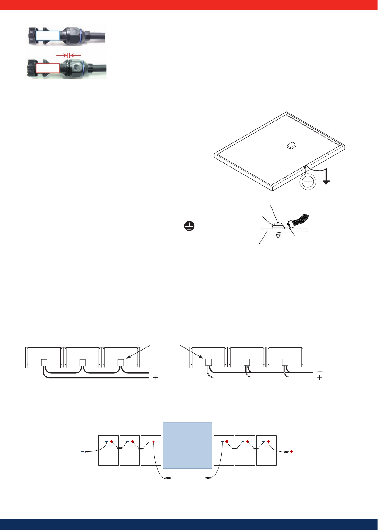
Figure 19
Series connection Parallel connection
Junction box
Carry out installation and wiring work in compliance with all relevant health, safety and environment laws and regulations.
Diagram showing standard module cabling with obstruction
If obstructions make it impossible to connect modules directly side-by-side, the plugs and sockets provided can be used to bridge gaps. A simple example is shown in
Figure 20:
Roof window
Extension Cable
Figure 20
good
not good
Fasten the sealing caps with a
fastening torque of 1.7 Nm.
Check that there is no gap
between the sealing cap and the
connector or socket.
Figure 16
5.3.3 Grounding
Grounding cautions
•Be aware of the necessary grounding requirements prior to installation. Your local
authorities can help you further.
•Install arrestors, surge absorbers or any other appropriate lightning protection tools
as needed.
•Module frames, mountings, connection boxes and metal conduits should be
connected to an earth ground as lightning protection, in accordance with local,
regional and national standards and regulations.
•Holes (d 4 mm, 0.16 in) are provided in the aluminium frame of the SF module to
accommodate grounding. The grounding cable must be attached to the module
frame with a screw and washer. There must be an electrical contact. Use a copper
grounding cable with a cross section of at least 2 mm² (AWG14) and a temperature
range of at least -40 to 85 °C.
•Alternatively, it is possible to use grounding lugs with integrated grounding pin,
lock washers and grounding clips or brackets for PV modules as per NEC Section
250. These components must be used in compliance with the grounding device
manufacturer's guidelines. Consult the grounding device manufacturer to identify
the appropriate grounding and bonding device for your mounting structure or
design.
For alternative grounding methods please consult Solar Frontier.
Connect the grounding cable to the point marked with the electrical earth symbol .
Please refer to further instructions provided by the screw or bolt manufacturer.
Figure 17
Rolling Thread Screw
Lock Washer
Crimping Terminal
Grounding Cable
PV module frame
Grounding (IEC)
Figure 18
5.3.4 Electrical wiring
•The SF modules have a connecting cable with one plug for each pole. Use these to connect the module.
•Do not open the junction box.
•Fasten the module cable to the frame or to the mounting system in order to avoid any stress to the connector.
•Cables drooping from the terminal box are hazardous and must be avoided.
•Cables should be secured so they are not exposed to direct sunlight (such as behind the module).
•The sum of Voc of modules in series must not exceed the maximum system voltage rating of the module under any condition, even at low temperature.
•Reverse current applied to the modules should not exceed 7 A under any condition.
•Minimum cable diameter: 2.5 mm² (0.004 in²).
8
ENGLISH
5.4 Installation of Turbo inverters
5.4.1 Safety measures during installation
Observe the following safety notes when performing the work described in sec-
tion Installation.
Danger
Risk of death by electrocution
• Only technical professionals may perform the work described in section Instal-
lation.
•Always disconnect all DC and AC cables as follows before starting work on the inverter:
1.
Turn the AC circuit breaker to off. Take measures to prevent the system from
being unintentionally switched on again.
2. Set the DC circuit breaker on the inverter to position 0. Take measures to
prevent the system from being unintentionally switched on again.
3.
Disconnect the Hosiden connectors of the DC cables according to
the manufacturer's instructions. A special tool is required for this.
Warning: DC cables are under current if light falls on the modules.
4. Remove the AC plug from the inverter as described in section 5.4.13.
5.
Check that all pins of the AC plug are free of voltage. Use a suitable voltmeter
for this (do not use a simple neon phase checker).
•Do not connect cables to the inverter until explicitly asked to do so in the
instructions.
•Do not open the casing of the inverter.
•Connect only SELV circuits to the RJ45 sockets.
•Lay the cables such that the connection cannot come loose accidentally.
•When laying cables, ensure that no damage occurs to any of the constructional
fire safety measures in the building.
•Make sure that no flammable gases are present.
•Observe all applicable installation regulations and standards, national laws and
connection values specified by the regional power supply company.
Attention
Danger of damage to the inverter or derating!
•The mounting location must satisfy the following conditions:
- The mounting surface and the immediate environment are stationary,
vertical, level, flame retardant and not constantly vibrating.
- They meet the requirements for environmental conditions; see 10.2. Technical
data for Turbo inverter.
- The inverter has the following clearances around it:
above/below: at least 200 mm
to the sides/in front: at least 60 mm
•Do not install the inverter in areas where animals are kept.
•Observe the connection ratings specified on the type plate.
• The DC cables must not be connected to an earth potential (DC inputs and AC
output are not galvanically isolated).
Attention
When transmitting data over a public network:
•Transmitting data over a public network can incur additional costs.
• Data transmitted over a public network is not protected from access by third
parties.
Advice
•Avoid exposing the inverter to direct sunlight.
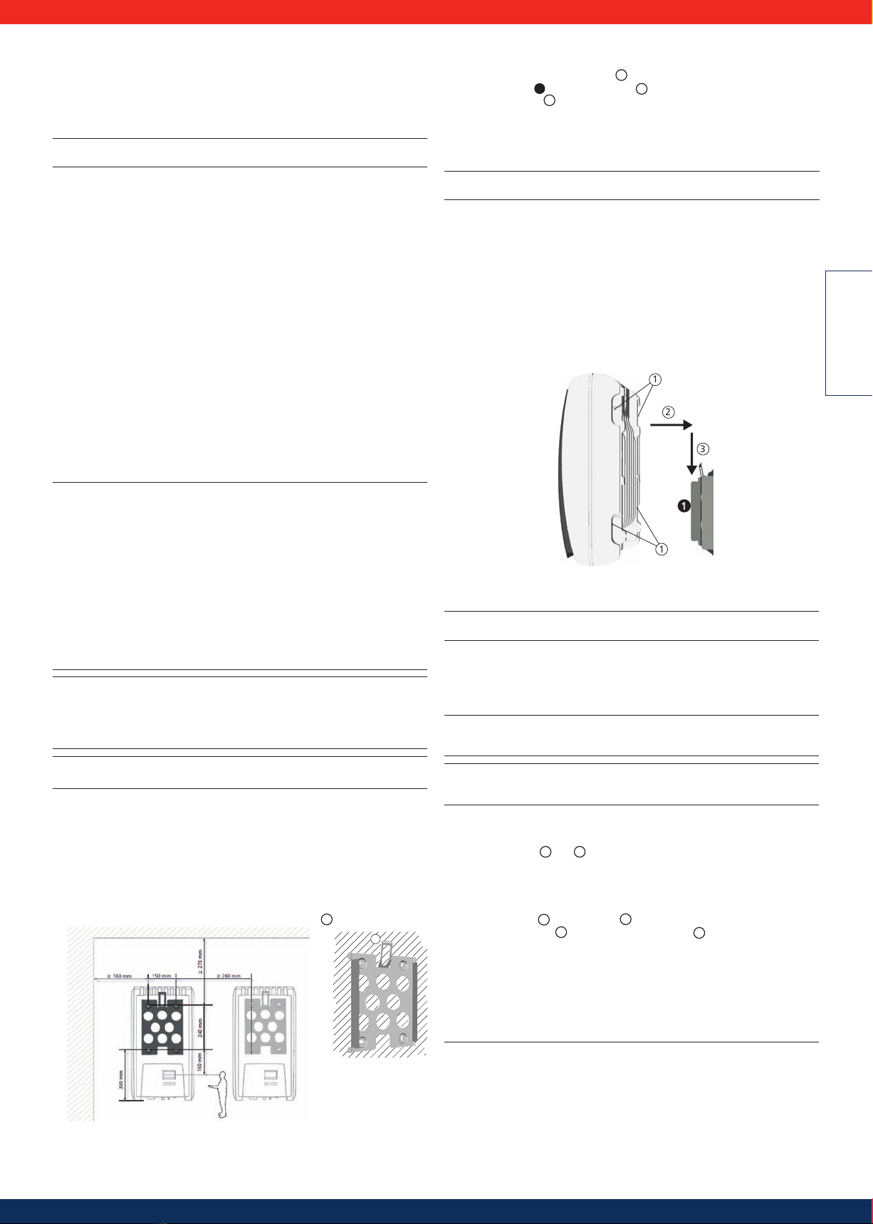
5.4.2 Mounting the inverter
Fastening the mounting plate
Screw the mounting plate to the mounting surface using 4 screws:
•Use screws (and dowels etc.) appropriate for the weight of the inverter.
•The mounting plate must lie flat on the mounting surface and the metal strips
at the sides must point forwards (Figure 22 ).
•Install the mounting plate vertically with the retaining plate
1
at the top (Figure 22).
Figure 22
Figure 21
1
Mounting the inverter on the mounting plate
1. Pick up the inverter by its handles 1or edges, place it in the middle of the
mounting plate 1and press in gently 2(Figure 23).
2. Lower the inverter
3
until the retaining plate on the mounting plate clicks
audibly into place.
The hooks on the back of the inverter must pass over the lugs on the mount-
ing plate.
3. The inverter must be firmly seated on the mounting plate and it must not be
possible to push it upwards.
Advice
The procedure for removing the inverter from the mounting plate is described in 6.4.9
5.4.3 Preparing the AC connections
Line circuit breaker
Information on the required line circuit breaker and the cables to be used between
the inverter and the line circuit breaker is provided in chapter 10.3.
Residual current circuit breaker
If the local installation regulations require the installation of an external residual
current circuit breaker, then a Type A residual current circuit breaker as per
IEC 62109-1, Section 7.3.8. is sufficient.
2
3
1
1
Figure 23
Wiring the AC plug
Danger
Risk of death by electrocution! Observe the warning notes in 5.4.1!
Grid voltage 220 V ... 240 V
Wire the AC plug supplied as described in 13.1.
Grid voltage 100 V ... 127 V
Danger
Risk of death by electrocution! Never connect one of the phases L1, L2 or L3 to PE
or N on the mains grid side.
Advice
If the grid voltage is between 100 V and 127 V, the inverter can be connected
between the external conductors L1, L2 and L3 as follows:
2-phase mains grids
•N and L are connected between the L1 – L2 external conductors on the
inverter side. See 2and 3in Figure 24.
•One of the two connected external conductors is connected to PE at the
inverter side. This connection can be made within the AC plug or in an external
junction box.
•Figure 24 shows an example of an inverter-side connection between L1 and PE:
Top: Connection 1in the AC plug 5
Bottom: Connection 4in an external junction box 6
3-phase mains grids
•N and L are connected between the L1 – L2 or L1 – L3 or L2 – L3 external
conductors on the inverter side.
•Connect the external conductor on the inverter side to PE: as above.
•Figure 24: as above.
The external conductor voltages are shown in Figure 25.
1. Wire the AC plug supplied to match the selected external conductors, as
described in chapter 13.1. Do not yet close the AC plug.
2. Connect one of the two connected phases to PE at the inverter side. Make this
connection inside the AC plug or use an external junction box; see Figure 24.

9
5.4.7 Modbus RTU data connection cable for connecting
an energy meter
A 4-pin telephone cable with RJ10 connector on the inverter side can be used as a
data connection cable to connect an energy meter for feed-in management.
Device
Connection
Inverter
RJ10
Signal
41
Contact 1 Data A
2 Data B
3 Ground
4 — Figure 27
Contact allocation (= wire num-
ber) of the RJ45 connector
Advice
•Material damage due to electrical voltage! The alternative data connection
cable may only be produced by a specialist.
•Risk of destroying the Modbus RTU input of the inverter. Contact 4 of the RJ10
socket carries voltages < 20V. Do not use this contact.
5.4.8 Connecting the inverter and switching on the AC power
Danger
Risk of death by electrocution! Observe the warning notes in 5.4.1.
Attention
Maintain a minimum clearance of 200 mm (7.87 in) between the data connec-
tion cables (RS485/Ethernet) and the DC /AC cables to prevent data transmission
interference.
•Before connecting the PV system to the grid, ensure that the complete system
has been checked, tested and approved in accordance with the relevant
regulations.
• Depending on local regulations, only accredited personnel may connect the
PV system to the grid and commission it.
1. If necessary, establish a data connection.
2. Push the Amphenol Helios H4 opposing connector of the DC cable firmly
into the DC connection of the inverter until it audibly clicks into place.
3. Insert the AC plug into the socket on the inverter until it audibly clicks into
place.
4. Switch on the AC line circuit breaker. The start page for initial commissioning
is shown on the display.
5. Perform initial commissioning and switch on the DC supply, as described in
5.4.9 and 5.4.10.
5.4.9 Initial commissioning of the inverter
Conditions for starting initial commissioning
Initial commissioning starts automatically when at least the AC connector has
been installed and switched on as described previously, If initial commissioning is
not fully completed, then it starts anew the next time the device is switched on.
Guided initial commissioning
Initial commissioning is a guided procedure that sets the following information:
•PowerSet
•Display language
•Date / Time
•Country
•Reactive power characteristic curve (if prescribed for the selected country)
Setting the country
The following applies when setting the country:
•The set country must always be the same as the country where the inverter is
installed. This causes the inverter to load the prescribed grid parameters for the
selected country. More information on this is provided in the table of countries
in section 10.4.
•The country can only be set once!
•If you have selected the wrong country, contact your installer or Solar Frontier.
•If you cannot select your country on the inverter, contact your installer or Solar
Frontier.
•The country setting does not affect the language used on the display. The
display language is set separately.
Only for the Turbo 1P Mini and Turbo 1P inverter:
Figure 24
Connecting N and PE
in the AC plug (top)
or distribution box (bottom)
1Connecting cable between N and PE with the connection point inside the AC plug
2External conductor L1
3External conductor L2
4Connecting cable between N and PE with the connection point in the junction box
5Casing of the AC plug
6Junction box
Figure 25
External conductor voltages
in 2 and 3 phase grids with
100 V ...127 V
L2
L3
L1
N
100 - 127 V
100 - 127 V
100 - 127 V
L
1
L
2
N
100 - 127 V
100 - 127 V
Only for the Turbo 3P1 / 3P2 inverter:
Wire the AC plug provided as described in the following Figure.
1Phase 1
2Phase 2
3Phase 3
4
As the inverter is protection class II.
the PE protective conductor has no
function and need not be connected.
5Neutral conductor
Figure 26
5.4.4 Preparing the DC connections
Danger
Risk of death by electrocution!
Use the SunClix connectors provided to maintain the specific protection class.
Attention
Danger of damage to the inverter and modules.
Connect the mating parts matching the DC connectors to the DC cable with the
correct polarity.
The Hosiden mating parts to the DC cable as per the instructions in section 5.3.2.
5.4.5 Prepare the data connection cable required for
using Power Monitoring
Provide an RJ45 standard cable (patch cable Cat5) to use the on-line Power Moni-
toring service or provide an alternative data connection cable as required.
5.4.6 Connecting a PowerStorage system
The initial operation and configuration of the PowerSet can be completed accord-
ing to these instructions when a PowerStorage system is used.
Thereafter, commission the PowerStorage system as described in the instructions
provided for this purpose. They describe all the necessary adjustments for the
PowerSet in detail.

10
ENGLISH
Operation
Starting initial commissioning
√ The check list for initial commissioning is
displayed.
• The PowerSet entry is selected.
• The checkboxes are not selected.
Advices
•When a check list item is called up the corre-
sponding checkbox is automatically selected.
• The following items are only displayed if the
use of a reactive power characteristic curve
is prescribed for the country selected in the
Country item:
•– Reactive power characteristic curve
(reactive power characteristic curve type)
– Number of nodes1)
– Node 11)
– Node 21)
– Node n1) 2)
– Display characteristic curve
1): Only displayed for reactive power character-
istic curve type Enter characteristic curve.
2): Only displayed if Number of nodes has
been set to a value > 2.
•Initial commissioning is completed by calling
up the Finish item.
•Finish can only be performed when all other
checkboxes are selected.
1. Press to select a check list item.
2. Press SET to call up the item.
The items are described separately below.
1. Press SET. The first digit of the PowerSet
code flashes.
2. Press to change the first digit of the
PowerSet code.
3. Press SET
.
The change is adopted.
4. Press . The second digit of the PowerSet
code is highlighted.
5. Repeat steps 1 to 3 for the second digit of
the PowerSet code.
6. Press ESC
.
The check list is shown.
Language
1. Press to select a display language.
2. Press SET
.
The language is adopted.
3. Press ESC. The check list is shown.
Date format
1. Press to select a date format.
2. Press SET. The date format is adopted.
3. Press ESC. The check list is shown.
Date
1. Press SET. The date flashes.
2. Press to change the day.
3. Press SET
.
The change is adopted.
4. Press . The month is selected.
5. Repeat steps 1 to 3 for the month.
6. Press . The year is selected.
7. Repeat steps 1 to 3 for the year.
8. Press ESC. The check list is shown.
Time format
1.
Press to select a time format.
2.
Press SET
.
The time format is adopted.
3. Press ESC. The check list is shown.
Time
1. Press SET. The hour display flashes.
2. Press to change the hour.
3. Press SET
.
The change is adopted.
4. Press . The minutes are selected.
5. Repeat steps 1 to 3 for the minutes.
6. Press ESC. The check list is shown.
Country selection
Advice
The country can only be set once!
1. Press to select a country.
2. Press SET.
3. Press ESC. The dialogue shown on the left is
displayed.
4. Press ESC to select a different country by
performing steps 1 and 2 or press
SET for a longer period of time (> 1 s) to
confirm the currently selected country. The
check list is shown.
Reactive power characteristic curve
1. Press ESC to call up this point.
2. to mark one type of reactive power
characteristic.
3. Press SET. The reactive power type is ac-
cepted.
4. Press ESC. The check list is shown..
Advice
: An additional Load Templates menu point
is shown when "cosPhi = 1" was not selected.
1. Press , to mark Load Templates.
2. Press SET.
3. Press , to select a standard characteristic.
4. Press SET.
Standard characteristic is accepted.
5. Press ESC. The check list is shown.
Number of nodes
1. Press SET. The value flashes.
2. Press to change the number of nodes.
3. Press SET. The value is adopted.
4. Press ESC. The check list is shown.
Node n
1. Press to select a parameter for the node.
Advice: P% cannot be changed at the first and last
nodes (000%.100%).
2. Press SET. The parameter value flashes.
3. Press to change the value.
4. Press SET
.
The change is adopted
.
5. If necessary repeat steps 1 to 4 for the other
parameters.
6. Press ESC. The check list is shown.
Display characteristic curve
1. The previously set reactive power characteristic
curve is displayed graphically (example in Fig.
left).
2. Press ESC. The check list is shown.

11
Advice:
The settings regarding the feed-in manage-
ment must be provided in the energy man-
agement sub-menu.
Modus
1. Press SET to call up this point.
2. Press to mark the energy meter or to
activate PowerStorage.
3. Press ESC.
4. Press ESC to move up one level to energy
management.
Dynamic feed regulation
Advice:
The power fed into the mains network is set
in 10 W steps.
It can be limited to a minimum of 0 W.
Conguration energy meters
Advice:
The inverter can only work with energy me-
ters that have already been pre-programmed
in the inverter. The pre-programmed energy
meters are listed under Meter Type.
1. Press SET to call up this point.
2. Press to mark the meter type.
3. Press ESC
.
4. Press ESC to leave the sub-menu.
Advice
:
The connection to the energy meter can be veri-
ed with a connection test.
5.4.12 Registration and conguring PowerMonitoring
The registration and the monitoring set-up can be performed once commission-
ing has been completed.
Please follow the link to be found on the sticker attached to the front of the device
housing. Follow the guided registration process to its end. Additional information
regarding registration can also be found at this link.
5.4.13 De-installing the inverter
Danger
Risk of death by electrocution!
Only technical professionals may perform the work described in section
De-installing the inverter.
Observe the warning notes in 5.4.1.
Switching o AC and DC supplies
1. Turn the AC circuit breaker to off.
2. Set the DC circuit breaker on the inverter to position 0
(Figure 29).
Figure 29
Finish
√ Finish has been selected in the check list
and SET has been pressed.
One of 2 possible dialogues is displayed.
1. Proceed as follows, depending on the dialogue
.
• Dialogue Settings are incomplete: Press SET and
work through the open items in the check list.
• Dialogue
Are all settings correct?
Press ESC to correct settings or press
SET for a longer period of time (> 1 s) to finish
initial commissioning.
2. If SET is pressed for a longer time then the
inverter restarts and synchronises itself with
the grid (Fig. left).
5.4.10 Switching on the DC supply
Set the DC circuit breaker on the inverter to position I
(Figure 31). After testing via the internal MSD (approx.
2 minutes), the power fed into the grid can be shown on
the display (assuming that sunlight is present).
Figure 28
5.4.11 Feed-in management or PowerStorage
Feed-in management or PowerStorage
It is also possible to use an energy meter for feed-in management. It must be con-
nected to the Modbus RTU interface and comply with the following requirements:
The inverter communicates with energy meters through the Modbus RTU. The
following applies:
• Only energy meters that were pre-programmed in the inverter can be used.
• The pre-programmed energy meters are:
• Herholdt ECS3, item number: ECSEM72
• Janitza ECS3, item number: ECSEM68MID
• B+G SDM630, item number: 1141103
• Carlo Gavazzi EM24, item number: EM24-DIN.AV9.3.X.IS.X
• The energy meter must measure in positive direction relative to the mains
network. Take note of the manufacturer's instructions
This menu point can alternatively be used to activate the PowerStorage function
when a Solar Frontier battery system is used. Details are provided in the Power-
Storage manual.
12
ENGLISH
Disconnecting DC connections from the inverter
Disconnect DC cables according to the manufacturer's instructions. A special
tool is required for this.
Warning
DC cables are under current if light falls on the modules.
Disconnecting the AC plug from the inverter
For the Turbo 1P Mini / 1P inverter:
1. Remove the AC plug from the socket on the inverter as described in chapter 13.1.
2. Check that all pins of the AC plug are free of voltage. Use a suitable voltmeter for
this (do not use a simple neon phase checker).
For the Turbo 3P1 / 3P2 inverter:
1. Disconnect the AC plug from the inverter: gently press in the ratchet near the
front of the AC plug with a suitable object to unlock it, and remove the plug.
2. Check that all pins of the AC plug are free of voltage. Use a suitable voltmeter for
this (do not use a simple neon phase checker).
Opening the AC plug (only if required)
For the Turbo 1P Mini / 1P inverter:
Open the AC plug as described in the Appendix under Mounting > AC plugs.
For the Turbo 3P1 / 3P2 inverter:
Open the AC plug: First open the cable gland at the back and then push in the
ratchets on the left and right of the plug casing (simultaneously) and unlock
with a suitable tool. Then remove the upper part of the casing from the con-
tact part.
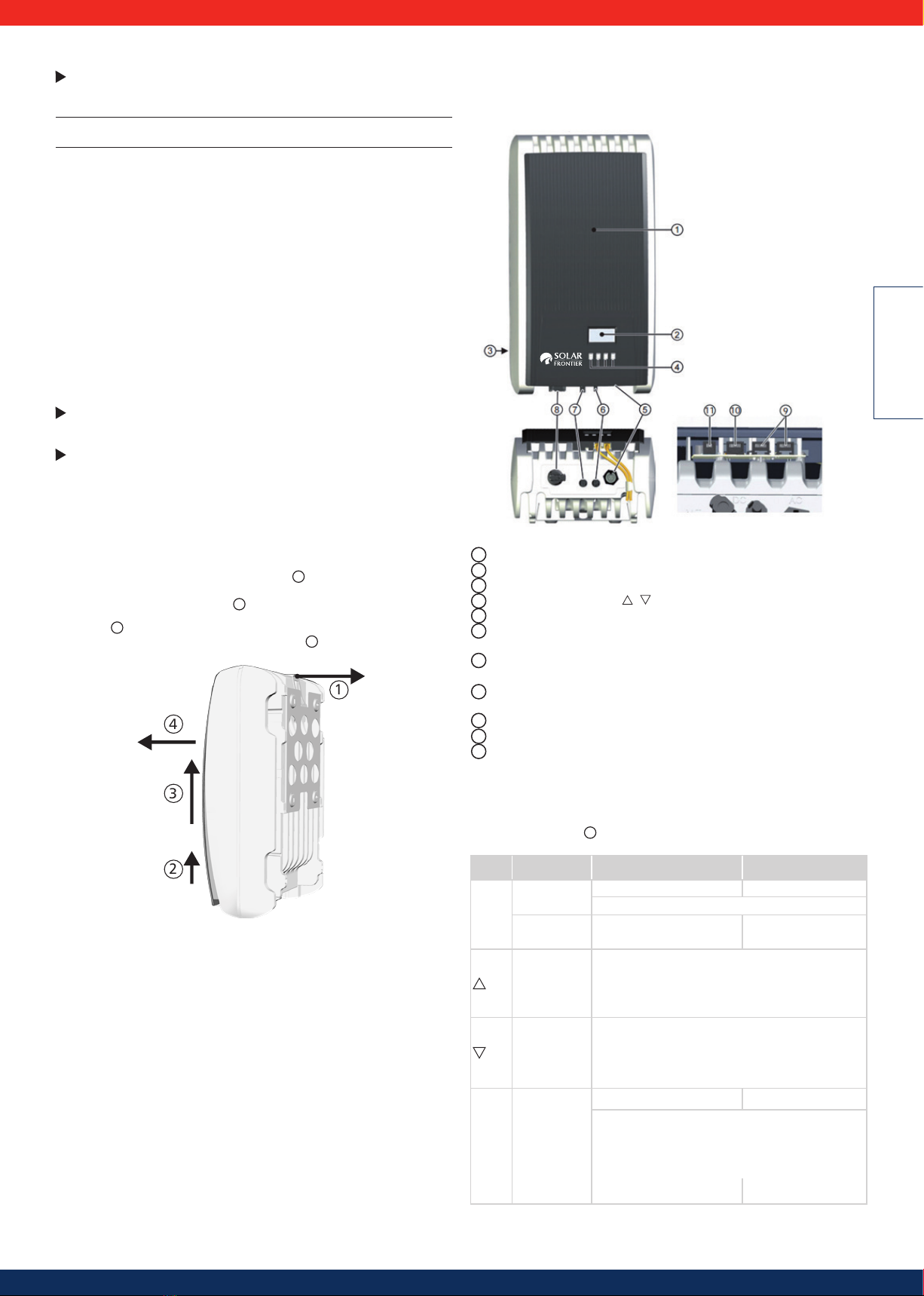
Removing the inverter from the mounting plate
1. Use one hand to press the retaining plate on the mounting plate approx.
5 mm (0.20 in) towards the mounting surface 1(Figure 30).
2. Use the other hand to push the inverter upwards, far enough so that the
retaining plate no longer latches. 2Release the retaining plate.
3. Lift the inverter with both hands until the hooks on the rear side of the inverter
are free 3
4. Remove the inverter from the mounting surface 4
3
1
2
4
Figure 30
6. Structure and function of the Turbo inverter
6.1 Casing
Figure 31
1Hood
2Display (monochrome, 128 x 64 pixels)
3Type plate, Serial number, warning notices
4Operating buttons: ESC, , , SET (from left to right)
51x AC connector
61x DC connector plus (+) for solar modules
(Phoenix Contact SunClix, insulated)
71x DC connector minus (−) for solar modules
(Phoenix Contact SunClix, insulated)
8DC circuit breaker
(interrupts plus and minus inputs simultaneously)
92x RJ45 sockets (RS485 bus)
10 1x RJ45 socket (Ethernet)
11 1x RJ10-socket (Modbus RTU)
The casing components are described in detail below.
6.2 Operating buttons
The operating buttons ( 4in Figure 31) have the following functions:
Button Action Function general Guided conguration
ESC
Press
briefly
jumps up by 1 menu level navigates 1 step
discards any changes
Press longer
(≥ 1 second) jumps to status display
jumps to the start of the
guided configuration process
Press
briefly
• moves the highlighted bar or the content of the
display up
• moves the highlighted position in a numerical setting
one digit to the left
• increases a setting by one step
Press
briefly
• moves the highlighted bar or the content of the
display down
• moves the highlighted position in a numerical setting
one digit to the right
• decreases a setting by one step
SET
Press
briefly
jumps down 1 menu level
–
• a selected numerical value begins to flash and can be
altered
• adopts any changes
• alters the state of a control (checkbox/radio button)
Press longer
(≥ 1 second)
answers a query dialogue with yes
navigates 1 step forward
Table 1

13
6.3 Overview of operating functions
For the sake of clarity, only the operating buttons and SET are illustrated.
SET SET SET
SET
SET SET
SET SET
SET
SET
SET
SET
Del. country
settting
Configuration
*)
Contrast
RS485
address *)
Network
Alarm
Self test *)
Backlight
Service
Self
consumption *)
Time/date
Remuneration
*)
Energy
management *)
Daily
Monthly
Annual
Yield
Remuneration
*)
Event log
Total
Contact info
System info
Country
setting
React. pwr.
char. curve *)
Autarky level *)
Settings
Self test *)
Operating
hours *)
Internal
temp. *)
Derating *)
Abs. max.
power *)
Day max.
yield *)
Max. daily
power *)
Status
display Main menu
Grid voltage
Gener. ch.
curve
Output power
Current day
yield *)
Grid current *)
Grid
frequency *)
PV voltage *)
PV current *) Meas. values
Reset max.
vals.
DHCP
IP addressLanguage
Clear
event log
Submenus
Information
DNS
Web portal
Subnet
mask
Gateway Voltage limits
off *)
PowerStorage
*)
Energy
meter *)
RS485
address *)
Dyn. feedin
control *)
Mode *)
Meter type *)
Reactive
power *)
*) Dieser Menüpunkt wird nicht immer angezeigt. Ob er vorhanden ist, hängt von den
Einstellungen am Wechselrichter und der Fimware-Version ab.
CO2 saving *)
Total yield *)
Frequency
limits
Voltage
limits Ø
Power limiter
Fixed voltage
Factory
setting
All parameters
Network
6.4 Service menu
The following section describes service menu items. Some items have password protection.
Obtain the password from technical support.
Attention
Risk of reduced yields. Inverter and grid parameters can be changed in the service menu. The service menu may only be used by technical professionals who can ensure
that the changes do not contravene the applicable regulations and standards.
14
ENGLISH
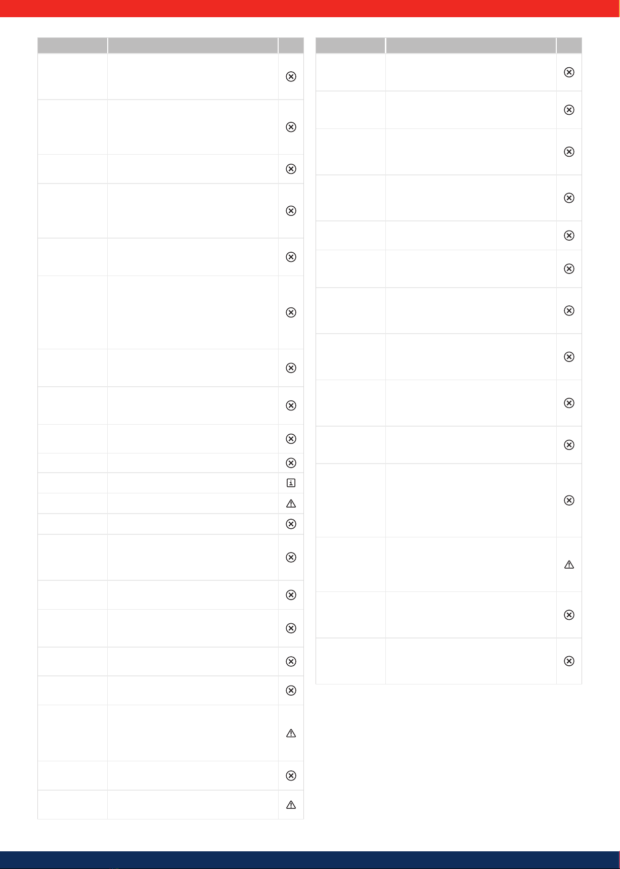
6.5 Troubleshooting
Faults are indicated by event messages as described below. The display flashes red.
Table 2 "List of event messages" contains information on troubleshooting and fault
correction.
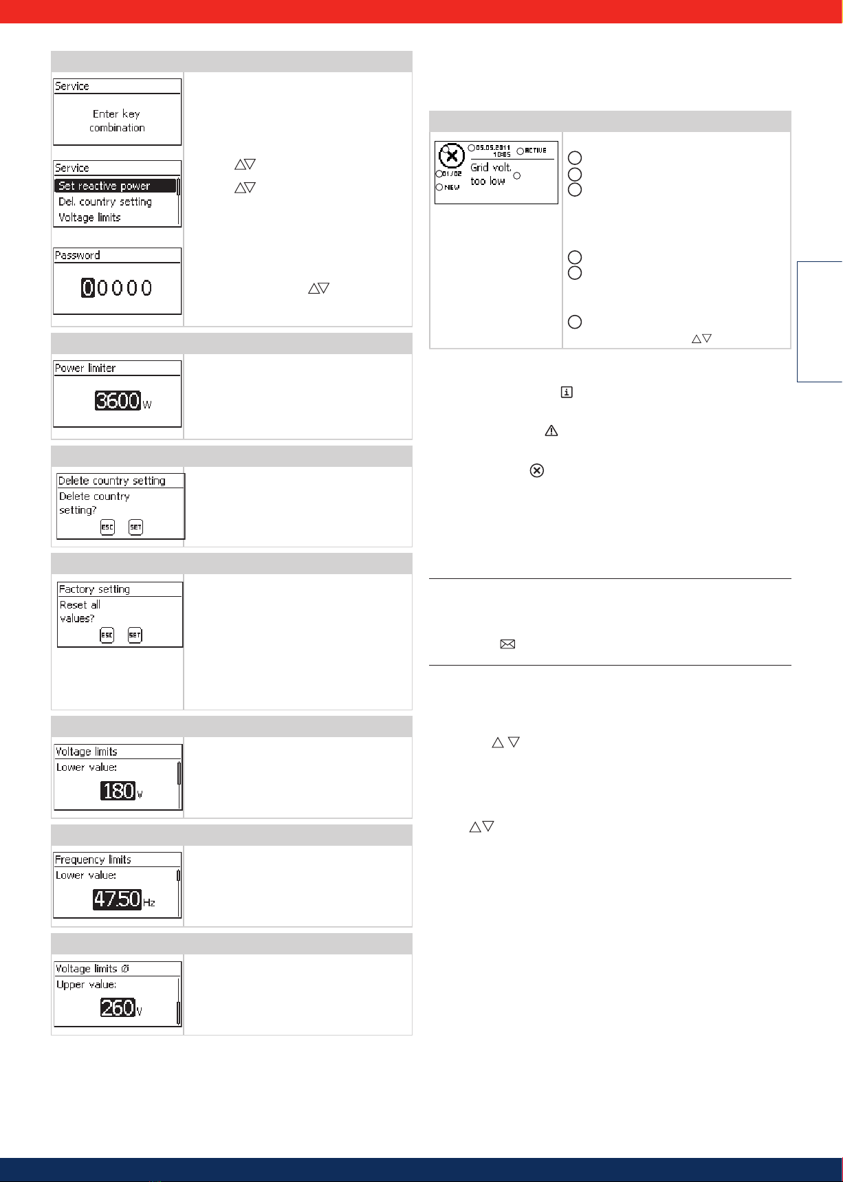
Structure
23
54
6
1Event messages have the following information:
1Symbol for the type of event message
2Date/time when the event occurred
3ACTIVE = The cause of the event message is
still present or
date/time when the cause of the event
message was corrected.
4Cause of the event message:
5Counter: No, of the displayed event message/
Total number of event messages;
max. total number of event messages = 30
6NEW is displayed until the event message is
confirmed using ESC or .
Function
Event message types
•Type Information (Symbol )
The inverter has detected an error that does not affect the feed-in process.
The user does not need to intervene.
•Type Warning (symbol )
The inverter has detected an error that may result in reduced yields. It is highly
recommended that you correct the cause of the error.
•Type Error (Symbol )
The inverter has detected a serious error. The inverter will not feed into the grid
while this error is present.
Please contact your installer. More information is provided in table 6“List of
event messages.”
Display behaviour
New event messages are displayed immediately. The messages disappear after they have
been confirmed or their cause(s) have been corrected.
Advice
When an event message is confirmed, the user thereby simply confirms that he/
she has seen the message. This does not correct the error that caused the event
message to be shown!
If messages exist whose cause has been corrected but which have not been
confirmed then is shown in the status display. If an already confirmed error
recurs then it is displayed again.
Operation
Conrming event messages
√An event message with the comment NEW is displayed.
Press ESC/ / . The event message is confirmed.
Displaying event messages
1. Select Event log in the main menu.
2. Press SET. The event messages are displayed in chronological order (latest
message first).
3. Press to page through the Event Messages.
Calling up the service menu and editing the values
1. Select the Service menu item.
2. Press SET. The fig. shown at the left appears.
3. Press simultaneously for 3 seconds.
The service menu is displayed (fig. left).
4. Press to select a menu item.
5. Press SET to go into the menu item.
The following applies:
• Enter the password if required (fig. left).
• Within a menu item press if required to dis-
play and alter further settings (e.g., voltage limits).
• - The menu items are described in section 9.3.4.
Power limiting
The inverter's output power can be restricted
manually to a minimum of 500 W. If the power is
manually restricted, the symbol Derating and the
reading Derating/reason: User default
are displayed in the status display.
Delete country setting
After the country setting has been deleted, the
device restarts and displays the guided initial
commissioning menu.
Factory setting
Resetting the device to the factory setting de-
letes the following data:
• Yield data
• Event messages
• Date and time
• Country setting
• Display language
• Network settings
After the factory setting has been deleted, the
device restarts and displays the guided initial com-
missioning menu.
Voltage limits (peak values)
The following voltage limits can be changed:
• Upper disconnection value 1)
• Lower disconnection value 1) (figure left)
1)
The disconnection value refers to the peak value
of the voltage.
Frequency limits
The following frequency limits can be changed:
• Upper disconnection value.
• Lower disconnection value (figure left)
• Derating switch-on threshold (because fre-
quency is too high)
• Frequency threshold when switching on again.
Voltage limits Ø (average value)
The following voltage limits can be changed:
• Upper disconnection value 1) (Figure left)
• Lower disconnection value 1)
• 1)
The disconnection value refers to the average
value of the voltage.
15
Event message Description Type
Data acceptance
failed
One setting, e.g. during commissioning, has failed,
as it was not correctly transmitted.
Repeat the setting.
Inform your installation company if the fault
persists.
Grid
islanding
detected
There is no grid voltage present (inverter running
independently). For safety reasons, the inverter
must not feed into the grid and switches off while
the error is present (dark display).
Contact your installer if this error occurs fre-
quently.
PE not
connected
The protective earth is not connected. For safety
reasons, the inverter must not feed into the grid.
Contact your installer.
Residual cur-
rent too high
The residual current flowing from the plus or minus
inputs to the earth via the photovoltaic modules ex-
ceeds the maximum permissible value. Due to legal
requirements, the inverter switches off automati-
cally for as long as the error state exists.
Contact your installer.
Faulty function of
boost converter
An internal component of your inverter is faulty. The
inverter does not feed or feeds with reduced power
into the mains network.
Contact your installer.
Device over-
heated
Despite derating, the maximum permissible tem-
perature has been exceeded. The inverter feeds no
power into the grid until the maximum permissible
temperature is no longer exceeded.
1. Check that the installation conditions are satis-
fied.
2. Contact your installer if the message occurs
frequently.
Boost converter
has wrong HW
version.
The inverter cannot recognise an internal component
or is not compatible with the other components. The
inverter cannot feed into the mains network.
Contact your installer.
Boost converter
not connected
The connection to the internal components is inter-
rupted. The inverter does not feed into the mains
network.
Contact your installer
Boost converter
defective
The boost converter is defective; the inverter is not
feeding into the grid or is feeding at reduced power.
Contact your installer.
Boost converter
not detected
Contact your installer.
Internal Info
Contact your installer if the message occurs
frequently.
Internal
warning
Contact your installer if the message occurs
frequently.
Internal Error
Contact your installer if the message occurs
frequently..
Insulation
error
The insulation resistance between the plus or minus
inputs and earth is less than the permissible value.
For safety reasons, the inverter must not feed into
the grid.
Contact your installer.
No branding The inverter has wrong or faulty device data. It can
therefore not feed into the mains network.
Contact your installer.
L and N swapped
The live and neutral conductors are wrongly con-
nected. For safety reasons, the inverter must not
feed into the grid.
Contact your installer.
Faulty country
setting
An inconsistency exists between the selected country
settings and those stored in memory.
Contact your installer.
Country param-
eter invalid
The inverter cannot feed into the mains network
because it does not have valid parameters.
Contact your installer.
Reduced perfor-
mance due to
temperature
The power inverter is reducing its output, as the maxi-
mum permitted temperature has been reached.
1. Check that the installation conditions are satis-
fied.
2. Contact your installer if the message occurs
frequently.
Reading of the
country setting
faulty
The inverter could not correctly read the country
selected from memory.
Contact your installer
Fan faulty
The internal fan of the inverter is faulty. In certain situ-
ations the inverter will feed less power into the grid.
Contact your installer.
Event message Description Type
Grid frequency
too high for
reactivation
After switching off, the inverter cannot resume
feeding because the grid frequency exceeds the
legally prescribed switch-on value.
Contact your installer if this error occurs frequently.
Grid frequency
too low for re-
activation
After switching off, the inverter cannot resume
feeding because the grid frequency exceeds the
legally prescribed switch-on value.
Contact your installer if this error occurs frequently.
Grid frequency
too high
The grid frequency at the inverter is greater than
the maximum permissible value. Due to legal re-
quirements, the inverter switches off automatically
for as long as the error state exists.
Contact your installer if this error occurs frequently.
Grid frequency
too low
The grid frequency at the inverter is less than the
minimum permissible value. Due to legal require-
ments, the inverter switches off automatically for as
long as the error state exists.
Contact your installer if this error occurs frequently.
Network relay
defective
The inverter has detected that a network relay is faulty
and therefore does not feed into the mains network.
Contact your installer.
Grid voltage
too low for re-
activation
After switching off, the inverter cannot resume
feeding because the grid voltage exceeds the
legally prescribed switch-on value.
Contact your installer if this error occurs frequently.
Grid voltage Ø
too high
The output voltage averaged over the legally
prescribed period of time exceeds the permissible
tolerance range. The inverter switches off automati-
cally for as long as the error state exists.
Contact your installer if this error occurs frequently.
Grid voltage Ø
too low
The output voltage averaged over the legally pre-
scribed period of time exceeds the permissible toler-
ance range. The inverter switches off automatically for
as long as the error state exists.
Contact your installer if this error occurs frequently.
Grid voltage
too high
The grid voltage at the inverter is greater than the
maximum permissible value. Due to legal require-
ments, the inverter switches off automatically for as
long as the error state exists.
Contact your installer if this error occurs frequently.
Grid voltage
too high for
reactivation
After switching off, the inverter cannot resume
feeding because the grid voltage exceeds the
legally prescribed switch-on value.
Contact your installer if this error occurs frequently.
BCONV over-tem-
perature
The maximum permissible boost converter tem-
perature has been exceeded. The inverter feeds no
power into the grid until the maximum permissible
temperature is no longer exceeded.
1. Check that the installation conditions are satis-
fied.
2. Contact your installer if the message occurs
frequently.
Time/date lost
The inverter has lost the time settings because it
was disconnected from the grid for too long. Yields
cannot be stored and event messages will have the
wrong date.
Correct the time under Settings/Time/
Date.
No connection to
the energy meter
There is no or no correct communication link between
the inverter and the energy meter (or the PowerStor-
age system).
Inform your installation company to have the
connection checked.
No connection to
PowerStorage
There is no or no correct communication link between
the inverter and the energy meter (or the PowerStor-
age system).
Inform your installation company to have the
connection checked.
Table 2
16
ENGLISH
7. Maintenance
7.1 Maintenance of Solar Frontier SF165-S/SF170-S
photovoltaic modules
A monthly visual check is highly recommended in order to maintain the efficiency
of SF modules and the security of the mounting.
•Remove any dirt, fallen leaves or bird droppings from the surface, and check
that there is no damage to the surface. Do not use detergent or chemicals
for cleaning dirt off SF modules as it may damage the modules and result in
degradation of insulation.
•Do not use hard brushes for cleaning. Use only soft cloths to remove dirt from
the modules.
•When replacement parts are required, be sure the installer/servicer uses parts
specified by the manufacturer with the same characteristics as the original
parts. Unauthorized substitutions may result in fire, electric shock or other
hazard.
•Stop using SF modules when any damage or unusual phenomena are ob-
served. Have them immediately replaced or removed by a qualified technician.
7.2 Maintenance DC system
The DC system is maintenance-free. It is still recommended that cables and con-
nectors are regularly checked for signs of damage.
7.3 Maintenance of Turbo inverters
The inverter is basically maintenance-free. Despite this, it is a good idea to regu-
larly check that the cooling fins on the front and rear sides of the device are free of
dust. Clean the inverter when necessary as described below.
Attention
Danger of destruction of components in devices.
•Do not allow cleaning agents and devices to penetrate between the cooling
fins at the front of the inverter (under the grey hood).
In particular, do not use the following cleaning agents:
- Solvent-based cleaning agents
- Disinfectants
- Coarse or sharp-edged cleaning materials
Removing dust
Dust should be removed using compressed air (max. 2 bar).
Danger
Risk of death by electrocution! Risk of death by electrocution.
Use cleaning agents only with a slightly damp cloth.
Remove heavy soiling with a slightly damp cloth (use plain water). If neces-
sary, use a 2% curd soap solution instead of water. After cleaning, remove any soap
residue using a slightly damp cloth.
8. Transport and Storage
Pay attention to all advice on the packaging when storing or transporting SF Power-
Sets. A dry room should be chosen for storage. The packaging is not waterproof.
All electronic components should be kept away from liquids during transport and stor-
age. The SF PowerSets must remain in the original packaging until the installation.
Small amounts of white powder from packaging material may adhere to the mod-
ules. This may safely be ignored and has no affect on performance.
9. Disposal
9.1 Disposal within the EU
This sign on the modules and inverters indicates that these
products must not be disposed of in household waste
when they reach the end of their life cycle.
For disposal and recycling, please take the products to
authorised collection points where you can hand them over
free of charge. Alternatively, in some countries you may
hand them in at the dealer's where you obtain your replace-
ment goods.
Please contact your local authority for further details on
your nearest authorised collection point.
The DC cables can be disposed of at municipal collection points as electric waste.
Penalties may be imposed for violation of the rules depending on the applicable law.
9.2 Disposal outside the EU
The symbol of a dustbin with a line through it is only valid in the European Union
(EU). If you want to dispose of your product please contact your local authority or
dealer to find out the correct disposal method.
10. Technical data and data sheets
10.1 Solar Frontier SF165-S/SF170-S photovoltaic modules
Electrical characteristics
Standard test conditions (STC)*1
Module SF165-S Module SF170-S
Rated output Pmax 165 W 170 W
Open circuit
voltage
Voc 110 V 112 V
Short circuit cur-
rent
Isc 2.20 A 2.20 A
Rated voltage Vmpp 85.5 V 87.5 V
Rated current Impp 1.93 A 1.95 A
Nominal operating
cell temperature (NOCT)*2
Module SF165-S Module SF170-S
Rated output Pmax 123 W 126 W
Open circuit
voltage
Voc 100 V 102 V
Short circuit
current
Isc 1.76 A 1.76 A
Rated voltage Vmpp 80.2 V 82.1 V
Rated current Impp 1.53 A 1.55 A
*1 Data measured under standard test conditions (STC) defined by the IEC standard
(1000 W/m² irradiance, 25 °C module temperature, AM 1.5 with tolerances of ±10% for
Isc and Voc and +10% / -5% for Pmax). The module efficiency with 200 W/m² irradiance is
typically 98% (±1.9%) of the STC efficiency.
*2 Nominal operating cell temperature (NOCT): Module operating temperature with 800 W/m2
irradiance, 20 °C air temperature, 1 m/s wind speed and in the open circuit condition.
17
Thermal characteristics
NOCT 47 °C
Temperature-coecient Isc α +0.01%/K
Temperature-coecient Voc β -0.30%/K
Temperature-coecient Pmax δ %-0.31%/K
Characteristics for system design
Maximum system voltage Vsys 1.000 V DC
Limiting reverse current Ir 7 A
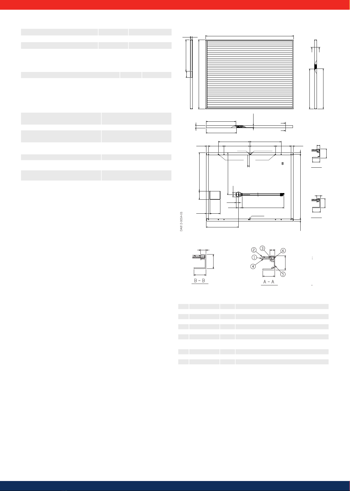
Mechanical Data
Dimensions (L x W x H) 1.257 x 977 x 35 mm
(49.5 x 38.5 x 1.4 in)
Weight 20.0 kg (44.1 lbs) / 16.3 kg/m2
(3.3 lbs/ft2)
Module operating temperature -40 °C to 85 °C
Application class
as per IEC 61730
Class A
Fire safety class
as per IEC 61730
Class C
Cable
2.5 mm2/ AWG14 (halogen free)
Snow load (to the front of the module) 2.400 Pa (IEC61646) / 1.600 Pa design
load (UL1703)
Wind load (to the back of the module) 2.400 Pa (IEC61646) / 1.600 Pa design
load (UL1703)
Module drawing
30
12
35
)
13,5
35
30
35
±0.5
A
A
φ
φ
φ
φ
427.1
±5
449.9
±5
(23.8)
1257
±2
977
±2
B B
90
(444)
20
565.5
±5
574.9
±5
(7)
±0 5
934
±2
598.5
±5
1200±100
2×Grounding
474.9
±5
88.1
66
47.8
21.5 21.5
120 (538.5)
150
(50)
31
±1
225 372.5 31
±1
225372.5
454.5 454.5
Mounting holes
Mountingholes
Label
8)
(-)
(+)
±2
4)
5 5
±5
9
±5
3
13.7
φ
φ
φ
φ
A-A
30
35
12
±5
φ
φ
φ
φ
L
B-B
30
35
13 5
4 × Ø 8.5
2 × Ø 4
2 × Ø 4.5
4 × Ø 6.6
No. Item Qty Description
1 Cell 1 CIS on substrate glass
2 Cover glass 1 Clear tempered glass
3 Encapsulant EVA
4 Back sheet Weatherproof plastic film
5 Frame 1 Set Anodized aluminium alloy / Colour:black
6 Edge sealant Butyl rubber
7 Junction box 1 With bypass diode
8 Cable 2.5 mm2(0.004 in²) / AWG14 (with waterproof
plug, Hosiden HSC - MC4 plug-in)
9 Adhesive Silicon
10 Label 1 Product label
11 Screw 8 Stainless tapping (SUS304J3)
12 Bar code label 1 Serial number

18
ENGLISH
10.2 Technical data for Turbo inverter
Turbo 1P Mini Turbo 1P Turbo 3P1 Turbo 3P2
DC input side (PV generator connection)
Number of DC inputs 1 1 1 1
Maximum start voltage 420 V 845V 1000 V 1000 V
Maximum input voltage 420 V 845 V 1000 V 1000 V
Minimum input voltage for grid-feeding 75 V 350 V 250 V 250 V
Startup input voltage 90 V 350 V 250 V 250 V
Rated input voltage 255 V 540 V 510 V 790 V
Minimum input voltage for rated output 180 V 360 V 375V 575 V
MPP voltage 75 V … 350 V 360 V … 700 V 375 V … 700 V 575 V … 700 V
Maximum input current 11.5 A 12 A 11 A 11 A
Rated input current 8 A 8 A 8 A 8 A
Maximum input power at maximum output active
power 2050 W 4310 W 4100 W 6330 W
Rated input power (cos φ= 1) 2050 W 4310 W 4100 W 6330 W
Derating/power limiting Occurs automatically when:
• input power > max. recommended PV power
• cooling is inadequate
• input current too high
• grid current too high
• internal or external derating
• grid frequency too high (according to country settings)
• limiting signal received via an external interface
• output power is limited (set at the inverter)
AC output side (mains grid connection)
Output voltage
(depending on the country setting) 185 V ... 276 V 185 V ... 276 V 320 V ... 480 V 320 V ... 480 V
Rated output voltage 230 V 230 V 400 V 400 V
Maximum output current 12 A 18.5 A 7 A 10 A
Rated output current 8.7 A 18.3 A 3.3 A 5.2 A
Maximum active power (cos φ= 1) 2000 W 4200 W 4000 W 6200 W
Maximum active power (cos φ= 0.95) 2000 W 3990 W 3800 W 5890 W
Maximum apparent power (cos φ= 0.95) 2100 VA 4200 VA 4000 VA 6200 VA
Maximum active power (cos φ= 0.9) - - 3600 W 5580 W
Maximum apparent power (cos φ= 0.9) - - 4000 VA 6200 VA
Rated output 2000 W 4200 W 4000 W 6200 W
Rated frequency 50 Hz and 60 Hz
Grid type
L / N / PE (protective earth ) L1/ L2/ L3/ N / FE L1/ L2/ L3/ N / FE
Grid frequency 45 Hz .., 65 Hz (depending on the country settings)
Power losses in nighttime operation < 2 W < 1 W < 3 W < 3 W
Feeding phases single-phase single-phase three-phase three-phase
Distortion factor (cos φ= 1) < 2 % < 2% < 1% < 1%
Power factor cos φ
0.95 capacitive ... 0.95 induc-
tive 0.95 capacitive ... 0.95 induc-
tive
0.8 capacitive ... 0.8 induc-
tive 0.8 capacitive ... 0.8 induc-
tive
Characterisation of the operating behaviour
Maximum efficiency 98.0 % 98.6% 98.6% 98.7%
European efficiency 97.5 % 98.2% 98.1% 98.3%
CEC efficiency 97.6 % 98.2% 98.4% 98.5%
MPP efficiency > 99.7% (static),
> 99% (dynamic) > 99.7% (static),
> 99% (dynamic) > 99.8% (static),
> 99% (dynamic) > 99.8% (static),
> 99% (dynamic)
Efficiency values (at 5%, 10%, 20%, 25%, 30%, 50%,
75%, 100% of the rated power) at rated voltage 92.8 %, 95.8 %, 97.3 %,
97.5 %, 97.7 %, 97.8 %,
97.7 %, 97. %
96.2%, 97.6%, 98.3%,
98.3%, 98.3%, 98.2%,
97.9%, 97.4%
91.0%, 95.5%, 97.5%,
97.9%, 98.1%, 98.4%,
98.6%, 98.3%
92.6%, 96.5%, 98.2%,
98.3%, 98.5%, 98.6%,
98.5%, 98.2%
Efficiency reduction in case of a rise in ambient
temperature (at temperatures > 40 °C) 0.005%/°C
Efficiency change in the case of deviation from the
DC rated voltage 0.002 %/V
Own consumption < 4 W < 4 W < 8 W < 8 W
Derating at full power from 50 °C (Tamb) from 45 °C (Tamb) from 50 °C (Tamb) from 50 °C (Tamb)
Switch-on power 10 W
Switch-off power 5 W 5 W 8 W 8 W
Safety
Protection class II
Isolation principle No galvanic isolation; transformerless
Grid monitoring Yes, integrated
Insulation monitoring Yes, integrated
Residual current monitoring Yes, integrated 1)
Overvoltage protection version Varistors
Reverse polarity protection Yes
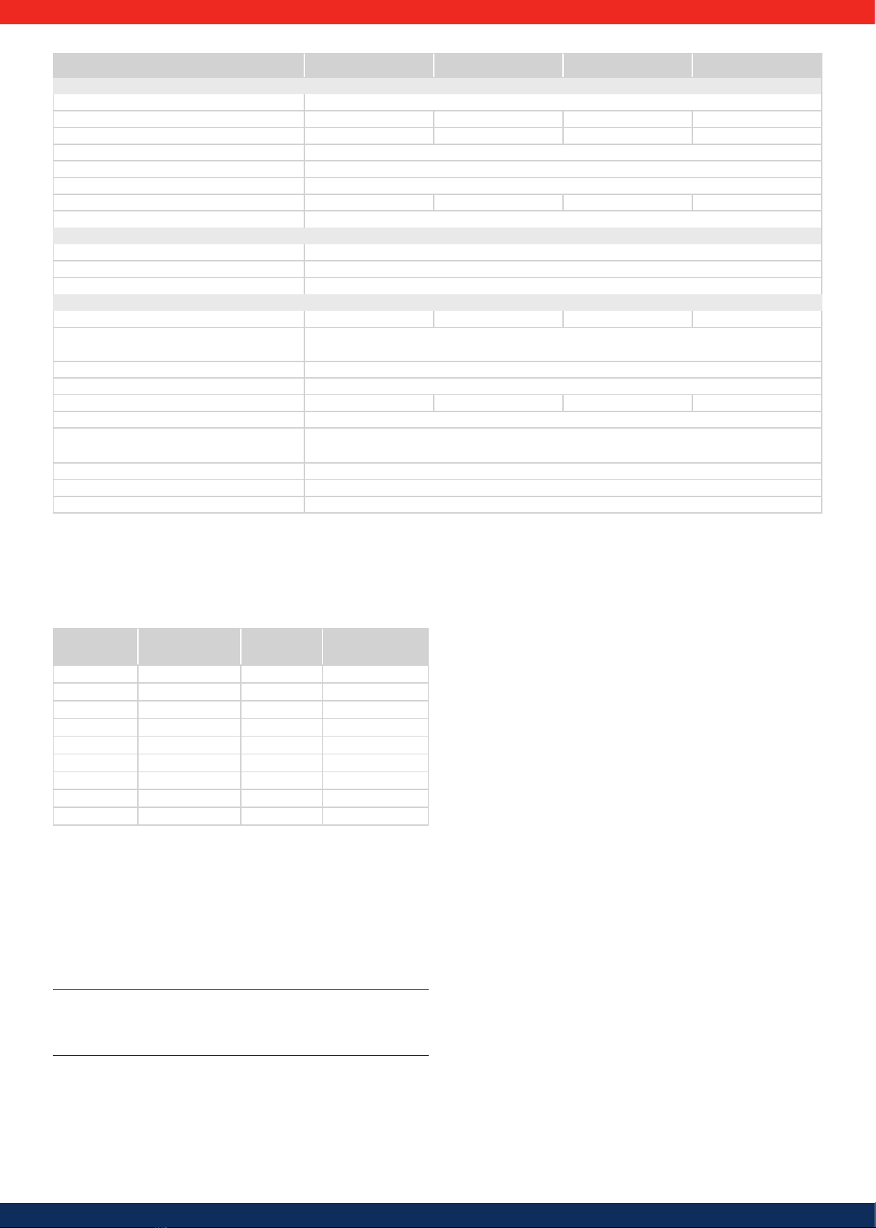
19
Turbo 1P Mini Turbo 1P Turbo 3P1 Turbo 3P2
Application conditions
Area of application Indoor rooms, with or without air conditioning
Ambient temperature range (Tamb) −15 °C ... +60 °C −15 °C ... +60 °C −15 °C ... +60 °C −15 °C ... +60 °C
Storage temperature -30 °C ... +80 °C -30 °C ... +80 °C -30 °C ... +70 °C -30 °C ... +70 °C
Relative humidity 0 % ... 95 %, non-condensing
Installation elevation ≤ 2000 m above sea level
Degree of pollution PD3
Noise emission (typical) 31 dBA 31 dBA 29 dBA 29 dBA
Impermissible ambient gases Ammonia, solvents
Equipment and design
Degree of protection IP21 (Casing: IP51; Display: IP21)
Overvoltage category III (AC), II (DC)
DC connection Phoenix Contact SunClix (1 pair)
AC connector
Type Wieland RST25i3 plug Wieland RST25i3 plug Wieland RST25i5 plug Wieland RST25i5 plug
Connection conductor cross-section Cable diameter 10 ... 14 mm 2
conductor cross-section ≤ 4 mm2
Opposing connector Included in delivery
Dimensions (X x Y x Z) 340 x 608 x 222 mm (49.5 x 38.5 x 1.4 in)
Weight 8.3 kg (16.47 lbs) 9 kg (17.86 lbs) 10 kg (19.84 lbs) 10 kg (19.84 lbs)
Display Graphical display 128 x 64 pixels
Communication interface RS485 (2 x RJ45 sockets: Connection to PowerStorage, 1 x RJ10 socket: Connection to Modbus RTU meter), ethernet
interface for PowerMonitoring (1 x RJ45)
Feed-in management as per EEG 2012 EinsMan Ready, via RS485 interface
Integrated DC circuit breaker yes, VDE 0100-712 compliant
Cooling principle Temperature-controlled fan, variable speed, internal (dust protected)
Table 3
Technical data at 25 °C/77 °F.
1) The design of the inverter prevents it from causing DC leakage current.
10.3 Technical data AC cable and line circuit breakers
Inverter AC cable conduc-
tor cross-section Power loss1) Line circuit breaker
Turbo 1P Mini 1.5 mm218 W B16
2.5 mm211 W B16
4.0 mm26 W B16
Turbo 1P 2.5 mm2 (0.0038 in²) 48 W B25
4.0 mm2 (0.0038 in²) 30 W B25
Turbo 3P1 2.5 mm² 7 W B16
4.0 mm² 4 W B16
Turbo 3P2 2.5 mm2 (0.0038 in²) 13 W B16
4.0 mm2 (0.0038 in²) 8 W B16
Table 4
1) Power loss of the AC cables at the rated power of the inverter and a cable length
of 10 m.
10.4 Table of countries
Details on setting the country are provided in section 5.4.7.
Turbo 1P Mini / 1p inverter
Advice
The requirements for the country-specific grid parameters may change at short
notice. Contact the technical support of Solar Frontier if the parameters specified
in the table no longer correspond to the legally prescribed requirements in your
country.
This manual suits for next models
9
Table of contents
Languages:
Other Solar Frontier Inverter manuals

Popular Inverter manuals by other brands


Afore
Afore HNS3000TL Installation and operation manual

Victron energy
Victron energy MultiPlus-II 48/3000/35 manual

Minarik
Minarik MM31002A user manual

SEW-Eurodrive
SEW-Eurodrive MOVIDRIVE system operating instructions

Unipower
Unipower SLI 15 Installation & operating manual

Link electronics
Link electronics HDG-820 Specification sheet

opti-solar
opti-solar 12W Green Energy Kit user manual

Growatt
Growatt MOD 4000TL3-X Installation & operation manual

SEW-Eurodrive
SEW-Eurodrive MOVAXIS MX Series operating instructions

SolarEdge
SolarEdge storedge installation guide

SIGLENT
SIGLENT SDG800 Series quick start

Siei
Siei QUIXDrive Inverters instruction manual