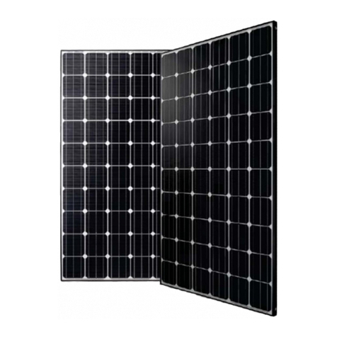
Solar Frontier SolarSet 2.0 User manual

Solar Frontier Europe GmbH
Installation and Operating Manual
SolarSet 2.0 / SolarSet 2.4 / SolarSet 3.1 / SolarSet 3.6 / SolarSet 4.1 /
SolarSet 4.8 / SolarSet 5.1 / SolarSet 6.1 / SolarSet 7.1 / SolarSet 8.2
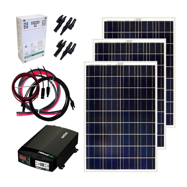
ENGLISH

2

3
Table of contents
1. Preface 5
2. Identication 5
3. General Safety Advice 6
3.1 Safety advice for photovoltaic modules of type Solar Frontier SF170-S 6
3.2 Safety advice for the inverter SF-WR 6
4. Proper Usage 7
5. Scope of Delivery 8
6. About this Manual 9
6.1 Contents 9
6.2 Target group 9
6.3 Markings 9
6.3.1 Symbols 9
6.3.2 Keywords 9
6.3.3 Markings used in the text 9
6.3.4 Abbreviations 10
7. Composition of the Solar Frontier SolarSets 11
8. Installation 12
8.1 Mounting system/ substructure 12
8.2 Mechanical installation of Solar Frontier SF170-S photovoltaic modules 12
8.2.1 Site location 12
8.2.2 Module handling instructions 12
8.2.3 Module mounting instructions 13
8.3 Electrical installation photovoltaic generator 17
8.3.1 Electrical wiring safety precautions 17
8.3.2 Cabling 17
8.3.3 Procedures for electric cabling 20
8.3.4 Grounding 20
8.3.5 Electrical wiring 21
8.4 Installation inverter SF-WR 24
8.4.1 Safety measures during installation 24
8.4.2 Mounting the inverter 25
8.4.3 Preparing the AC-connection 26
8.4.4 Preparing the DC-connections 27
8.4.5 Connecting the inverter and switching on the AC-power 28
8.4.6 Initial commissioning of the inverter 28
8.4.7 Switching on the DC-supply 32
8.4.8 De-installing the inverter 32

4
9. Structure and Function of the Inverter SF-WR 33
9.1 Casing 33
9.2 Operating buttons 33
9.3 Display 34
9.3.1 General information 34
9.3.2 Information 34
9.3.3 Settings 36
9.3.4 Service menu 38
9.4 Cooling 40
9.5 Grid monitoring 40
9.5.1 Data communication 40
9.6 Operation 44
9.6.1 Overview of operating functions 44
9.6.2 General operating functions 45
9.6.3 Main operating functions 45
9.7 Self test (mandatory in Italy) 48
9.8 Troubleshooting 50
10. Registration and warranty 53
11. Maintenance 53
11.1 Maintenance Solar Frontier SF170-S photovoltaic modules 53
11.2 Maintenance DC-System 53
11.3 Maintenance inverter SF-WR 53
12. Accessories 54
13. Transport and Storage 54
14. Disposal 54
14.1 Disposal of Solar Frontier SF170-S photovoltaic modules 54
14.2 Disposal of Solar Frontier inverter SF-WR 54
14.3 Disposal of DC-cabling 54
15. Technical Data, Data Sheets and Certicates 55
15.1 Solar Frontier SF170-S photovoltaic module 55
15.1.1 Technical data 55
15.1.2 Certicates for Solar Frontier SF170-S 58
15.2 Inverter 59
15.2.1 Technical data inverter 59
15.3 Technical data AC-cable and line circuit breakers 61
15.4 Table of countries 61
15.5 EU – Declaration of conformity inverter SF-WR 63
15.6 Plugs and Sockets 65
15.6.1 Product information plugs and sockets 65
15.6.2 TÜV certicate plugs and sockets 66
15.6.3 Product information DC-cable 67
15.6.4 EU declaration of conformity DC-cable 68
15.6.5 TÜV certicate DC-cable 69
16. Exclusion of Liability 70
17. Contact 70
18. Notes 71
19. Appendices 72
19.1 Installation SF-WR 72
19.2 AC-plug SF-WR 73

5
1. Preface
Thank you for choosing a SolarSet with CIS photovoltaic modules from Solar Frontier. Solar Frontier (SF) oers the highest standards in
creating electrical power from solar energy, and in customer service.
This manual contains important information with regards to the installation, operation, maintenance, cabling and use of the SolarSet,
and the safety instructions involved. To ensure a proper and safe use of the SolarSet, all tips and warnings in this document, as well as
the advice of the manufacturers of the system components should be carefully read, understood and applied. Please make sure that
the installer and operator of the plant obtain a copy of this manual. Please save this document for future use. All applicable local and
national laws and norms should be obeyed during installation, cabling, operation and maintenance of the SolarSet. In case of further
questions please get in touch with your dealer or with Solar Frontier directly.
2. Identication
Type plate of the Solar Frontier inverter Type plate of the SF module
SF-WR
1
1
2
3
4
5
6
7
8
9
1
2
3
4
5
6
7
8
9
Barcode for internal purposes
Technical Data –DC-input
Article number and product designation
Manufacturer
Protection Class II and CE symbols
Country of manufacture
Technical Data – AC-output
Protection classication and grid-monitoring standard
Serial number (and barcoded serial number)
2
3
4
5
6
7
1
2
3
4
5
6
7
Certications and protection classes
Serial number (and barcoded serial number)
Name of product
Technical data at STC
Manufacturer and country of manufacture
General product characteristics
Serial number on frame
Figure 1 Figure 2
Alle Rechte bei Steca Elektronik GmbH, auch für den
Fall von Schutzrechtsanmeldungen. jede Verfügungs-
befugnis, wie Kopier- und Weitergaberecht, bei uns.
C
0
10
20
30
40
50 mm
Ausdruck unterliegt nicht dem Änderungsdienst Blatt 1/1
Zust.
Z01
Änderung
ohne Änderung
Datum Name
Bearb.
Gepr.
Datum Name
Steca
Etikett
Michler
ZET-STSP-NET
10.36.854
749.591
31.07.13 31.07.13
SF-WR-3600
Typenschild
Elektronik
K:\Stsp\WR\Steca_Grid_3600\Schilder\1036854_1-et.ai
Alle Maße ohne Toleranzangabe ±0,2mm
NM
Burger
31.07.13
Manufacturer:
Steca Elektronik GmbH
DC Input: AC Output:
Voltage: 350 - 845V
MPP Voltage: 350 - 700V
Current: max. 10A
Voltage: 230V, 50/60Hz
Power Factor: 0,95 - 1,0
Current: max. 16A
Power: max. 3600W
Model:
SF-WR-3600, StecaGrid 3600
Art. number:
KIT10001, 749.591
IP classification: IP 21
Overvoltage category: III
According to:
VDE 0126-1-1:A1,
VDE AR N 4105
50,8
57
Made in Germany
Schrifttyp: Humanist 777 BT
Selbstklebende Alufolie (silber), mit schwarzem Aufdruck
unbedrucktes Etikett: 744.196
Achtung:
Das CE-Zeichen muss mindestens 5mm hoch sein !
Hinweis:
Feld für Barcode
für Produktion
(letzte 4 Stellen
der Seriennummer)
13/07/22
SD-010-023-05
SD-010-023-05
SD-010-023-05
MADE IN JAPAN
SF170-S
XXXXXXXXXXXXXX
BARCODE
112
2.20
20.0
2400 33.4
170
87.5
1.95
+10 -5

6
3. General Safety Advice
Please ensure all necessary measures are taken to prevent accidents. The use of SolarSets in applications that may endanger human
lives is prohibited, including in air and road transport systems. SolarSets must not be used for anything other than their expressed
purpose.
Solar Frontier strongly advises you to follow the instructions below in order to avoid bodily injury, damage to property and/or death.
SolarSets sold by Solar Frontier GmbH may only be installed by authorized professionals (see 6.2). As soon as it becomes
evident that safe operation is no longer possible (e.g. visible damage), remove the SolarSet immediately from the grid.
3.1 Safety advice for photovoltaic modules of type Solar Frontier SF170-S
•Installation, wiring, and maintenance of SF modules must only be carried out by licensed and trained persons.
•Ensure that all instructions and information related to SF modules and other balance of system components are fully understood
prior to handling and installing a PV solar system.
•The front surface of SF modules should be covered with an opaque material during installation to decrease the potential of electri-
cal shock.
•SF modules only generate direct current (DC) electricity.
•SF modules do not have the ability to store electricity.
•SF modules will experience higher voltage when connected in series and higher electrical current when connected in parallel.
•Only interconnect SF modules with similar electrical characteristics in series or in parallel to prevent system imbalance conditions
and module damage.
•The PV array open-circuit voltage must never exceed the maximum system voltage (including in low temperature conditions).
•Leakage currents could create a shock hazard or re.
•Do not disconnect operational modules or electrical arcing may occur. This may result in serious bodily harm or death.
•Do not use SF modules for purposes other than terrestrial power generation to prevent electrical shock, re or other accidents.
•Do not articially concentrate sunlight on modules using lenses or mirrors.
•Do not use light sources other than natural sunlight and general illumination for power generation.
•Do not use SF modules in water or liquid. There is a serious risk of electric shock, an electric leak or an accident.
•The level of leakage current must be limited in accordance with local regulations for safety reasons.
•Carefully check the polarity of the wiring before installing. Incorrect wiring may damage SF modules or appliances.
•Only use equipment, connectors, wiring and support frames suitable for solar electric systems.
•Wear appropriate protection and take all necessary precautions to prevent electric shock, especially when DC-voltage exceeds
30 VDC.
3.2 Safety advice for the inverter SF-WR
•Install and use the device only after reading and understanding this document.
•Always perform the measures described in this document in the sequence specied.
•Keep this document in a safe place for the entire service life of the device. Pass the document on to subsequent owners and opera-
tors of the device.
•Improper operation can reduce the yields of the photovoltaic system.
•The device must not be connected to the DC- or AC-cables if it has a damaged casing.

7
•If one of the following components is damaged, immediately take the device out of operation and disconnect it from the mains
grid and solar modules.
- Device (not functioning, visible damage, smoke, etc.)
- Cables
- Solar modules
•The system must not be switched on again until:
- The device has been repaired by a dealer or the manufacturer.
- Damaged cables or solar modules have been repaired by a technical specialist.
•Never cover the cooling ns.
•Do not open the casing. This will void the warranty and could result in serious bodily harm or death.
•Factory labels and markings must never be altered, removed or rendered unreadable.
•Observe the respective manufacturer‘s manual when connecting an external device that is not described in this document (e.g.
external data logger). Incorrectly connected devices can damage the inverter.
Safety advice on the inverter
4
5
1
23
10min
Isoler les deux sources
avant toute
intervention
Attention
Présence de deux sources
de tension
- Réseau de distribution
- Panneaux photovoltaïques
S/N: 746867XG001155550005
4. Proper Usage
The SolarSet may only be used in grid-connected photovoltaic systems. The modules, inverter, cables, and connectors have been
mutually calibrated for best performance. The connections may not be grounded.
Potential curves of the photovoltaic voltage VPV at 350V and 550V
VPV = Potential between plus and minus poles at the DC-input
1Dangerous voltages can remain present on the compo-nents up
to 10 minutes after switching o the DC circuitbreaker and the
line circuit breaker.
2Warning. There are 2 voltage sources present:
powergrid, solar modules.
3Disconnect both voltage sources from the device beforeworking
on the device: the solar modules via the DC circuit breaker and
the power grid via the line circuitbreaker.
4Disconnect both voltage sources from the device before
working on the device:
The solar modules via the DC-circuit breaker and the power
grid via the line circuit breaker.
5Read and follow the instructions!
Figure 3
Figure 4
175 V
− 175 V
− 275 V
275 V
320 V
U
t
0 V
− 320 V
UPV = 350 V
DC (+)
DC (−)
175 V
−
175 V
−
275 V
275 V
320 V
0 V
−
320 V
U
t
UPV = 550 V
DC (+)
DC (−)
Abb. 2: Potentialverlauf von UPV bei 350 V (links) und 550 V (rechts)
175 V
− 175 V
− 275 V
275 V
320 V
U
t
0 V
− 320 V
UPV = 350 V
DC (+)
DC (−)
175 V
− 175 V
− 275 V
275 V
320 V
0 V
− 320 V
U
t
UPV = 550 V
DC (+)
DC (−)
Abb. 2: Potentialverlauf von UPV bei 350 V (links) und 550 V (rechts)

8
5. Scope of Delivery
The Solar Frontier SolarSet comprises the following components. The number of components required can be determined using the
list below based on the type of SolarSet you have:
1Photovoltaic module Solar Frontier SF170-S
2Solar Frontier inverter SF-WR (incl. Inverter, Mounting plate and AC-plug)
3Connecting cable (Versions for + and -, with either 2, 3 or 4 outputs)
4DC-cable (in 50m or 100m)
5DC-plugs und DC-sockets (5 of each in each package unit)
6Unlocking tool
7Installation Manual
2.0 2.4 3.1 3.6 4.1 4.8 5.1 6.1 7.1 8.2
1SF170-S 12 14 18 21 24 28 30 36 42 48
2SF-WR-XXXX 1111122222
3Connecting cable 2222244444
4DC-cable [m] 50 50 50 50 50 100 100 100 100 100
5Plugs & Sockets 5 5 5 5 5 10 10 10 10 10
6Unlocking tool 1111122222
7Installation Manual 1111111111
Table 1
Not scope of the delivery are:
•Installation scaolding and installation materials
•Tools for installation and confectioning of the cables

9
6. About this Manual
6.1 Contents
This manual contains all the necessary information that an installer or professional requires to install the SolarSet and put it into opera-
tion. Please note the instructions provided by component manufacturers (e.g. AC-cable, substructures).
6.2 Target group
The target group for this manual are professionals and installers, unless otherwise stated.
„Professionals“ means the persons that:
•Have the necessary expertise and knowledge with regards to the terms and skills needed to install and operate photovoltaic systems.
•Have sucient experience, professionally trained, knowledgeable, and aware of the safety work regulations, applicable laws and
norms of the following:
- Installation of electrical appliances
- Assembly and connection of data cables
- Assembly and connection of power supply lines
6.3 Markings
6.3.1 Symbols
Symbol Description Location
General safety advice Manual
Danger from electricity Manual
Device
Read manual before use. Device
6.3.2 Keywords
Keyword Description
Danger Immediate danger of death or serious injury
Warning Possible danger of death or serious injury
Caution Possible danger of light or medium injury
Notice Possible damage to property
Note Tips on operation or usage of the manual
6.3.3 Markings used in the text
Marking Description
√Condition for action
Single step
1., 2., 3., ... Several steps in series
cursive light emphasis
bold strong emphasis
Courier Designation of product elements such as buttons, displays, operating state

10
6.3.4 Abbreviations
Abbreviation Description
ACurrent in Amperes
AC Alternating current
ca. circa
i.e. that is
DC Direct current
Derating Power reduction
MSD Internal grid monitoring of the inverter (Mains monitoring with allocated Switching
Devices).
tot. total
lCurrent
lkShort circuit current
Impp MPP circuit current
incl. inclusive
kVA Kilovoltampere
kW Kilowatt
kWh Kilowatthour
mMeter
m2Square meter
MPP maximum power point
Nm Newtonmeter
PElectrical power
Pa Pascal
PV Photovoltaic
SELV Safety Extra Low Voltage
SF Solar Frontier
STC Standard Test Conditions
UVoltage
et al and others
ULOpen circuit voltage
Umpp Voltage im Maximum Power Point
UPV Voltage of the generator at the DC-connection (photovoltaic voltage)
etc. and so on
VVolt
W/m2Watt per square meter
e.g. for example
ηEciency

11
7. Composition of the Solar Frontier SolarSets
Solar Frontier currently oers ten dierent Solarsets with nominal power outputs from 2.0 kW to 8.2 kW. The SolarSets consist of Solar
Frontier modules, Solar Frontier inverter(s), the necessary connecting cables, DC-cable and plugs and sockets.
Table shows the exact composition of each SolarSet, including the electrical structure:
Position Description 2.0 2.4 3.1 3.6 4.1 4.8 5.1 6.1 7.1 8.2
Module SF170-S 12 14 18 21 24 28 30 36 42 48
Inverter SF-WR-3000 1 1 1 1 2 2 1
Inverter SF-WR-3600 1 1 2
Inverter SF-WR-4200 1
Roof Area Area in m215,6 18,2 23,4 27,3 31,2 36,4 39 46,8 54,6 62,4
Module Number in Series 6 7 6 7 6 7 6 6 7 6
Strings Number parallel 2 2 3 3 4 4 5 6 6 8
Connecting cable 2+ 1 1 2 1
Connecting cable 2- 1 1 2 1
Connecting cable 3+ 1 1 1 2 2
Connecting cable 3- 1 1 1 2 2
Connecting cable 4+ 1 2
Connecting cable 4- 1 2
DC-cable 50 Meter 1 1 1 1 1
DC-cable 100 Meter 1 1 1 1 1
Plugs 5 pces. 1 1 1 1 1 2 2 2 2 2
Sockets 5 pces 1 1 1 1 1 2 2 2 2 2
Unlocking tool Number 1111122222
Table 2
Schematic structure based on SolarSet 3.1
Figure 5 shows the schematic structure of the SolarSet. The modules are connected serially to strings. The outputs of each single string
are drawn together using the appropriate connecting cable. The connecting cables have to be assembled on the spot, and serve to
extend the connection to the inverter.
The connecting cables have two, three or four
outputs depending on the plant size. Cables are
provided for each polarity (plus and minus).
Figure 5

12
8. Installation
For a safe installation, all relevant national and local laws, regulations and directives, especially for accident avoidance,
as well as all relevant technical standards are to be adhered to.
8.1 Mounting system/ substructure
The SolarSets are delivered without mounting systems. In general, all mounting systems commercially available, are suitable (e.g. No-
votegra (MHH), HatiCon, K2 Mounting Systems, Easy Roof (IRFTS), Schletter, Tritec) provided that the installation is in accordance with
the requirements indicated in 8.2.3. Your installer will be able to suggest a suitable solution.
8.2 Mechanical installation of Solar Frontier SF170-S photovoltaic modules
8.2.1 Site location
•Ensure that the maximum wind and snow loads in local conditions do not exceed the SF module maximum load ratings.
•Avoid installing SF modules in areas where they are exposed to oil vapour and /or corrosive gas.
•Avoid accumulation of grit or dust on the SF modules as it may inuence the output yield.
•Do not expose SF modules to sulphurous atmospheres.
•Do not install SF modules in locations where ammable gases accumulate or ow as there is a risk of sparks from SF PV modules.
•Do not install SF modules near re.
•Avoid installing SF modules in locations where they may be covered by permanent shadows. This may adversely aect their perfor-
mance.
•Do not install SF modules in locations where temperatures exceed the temperature range indicated in the module’s technical
specications
8.2.2 Module handling instructions
•Do not disassemble or modify SF modules. This may result in an electric shock, re or other accidents. Solar Frontier cannot be held
responsible for any loss or damage caused by unauthorized disassembling, modication or misuse of SF modules.
•Do not drill additional mounting holes into the aluminum frame. Only pre-drilled holes should be used.
•Avoid placing any stress onto the SF modules, cables or connectors.
(Minimum bending radius of 39 mm for module cables is recommended)
•Do not stand or step on SF modules. This may result in damage to the module and/ or bodily harm by falling.
•Do not drop SF modules or drop objects onto them. Both sides of the module (the glass surface and the back sheet) are fragile.
•Do not strike the terminal box or pull the cables. The terminal box can crack and break, while the output cable may unplug and
cause electricity leakage or an electric shock.
•Do not scratch the back sheet or cables of the SF modules. Rubbing or scratching may result in an electric shock, electric leakage or
an accident.
•Do not scratch the insulation coating of the frame (except for the grounding connection). This may weaken the strength of the
frame or cause corrosion.
•Do not cover the water drain holes of the frame. Doing so may cause frost damage.
•Do not use glue when closing the cover of the junction box. Similarly, do not use a sealant to bond the junction box lid to its base.

13
8.2.3 Module mounting instructions
Mounting structures cautions
•Pay attention to the electrochemical series when selecting support structure material to avoid galvanic corrosion.
•Fasten and lock bolts completely. Inadequate mounting may result in SF modules falling or other accidents.
•Ensure that the SF modules are securely fastened to the mounting support structure that is durable, made of UV and corrosion
resistant material, and follow the applicable local and civil codes.
•Ensure that your mounting support structure is designed to withstand the SF module design snow and wind loads applicable for
the chosen site. Solar Frontier will not be responsible if the SF modules are damaged due to the durability of the mounting support
structure. Please consult your mounting structure manufacturer.
Mounting the solar modules
•PV modules should typically face South in the Northern Hemisphere and North in the Southern Hemisphere for optimal power
production.
•Modules can be installed horizontally (landscape) or vertically (portrait).
•Maintain a space between SF modules and the roof. This will allow air to circulate, cooling the module, and allowing condensation
to dissipate. Solar Frontier recommends a distance of at least 100 mm (3.94 in).
Mounting with Screws
SF modules should be fastened to the support structure using the mounting holes on the frame. The support structure should be
securely fastened to a non-corrosive roof. Tighten the screws with an adequate torque value. Please refer to further instructions and
adequate torque value provided by the screw manufacturer.
Mounting with Inner Holes
Each module will require four M6 (or 1/4 in) bolts with washers, lock washers and nuts. Tighten the screws with an adequate torque value.
UL: Recommended tightening torque is 8 Nm (70.8 lb in) minimum.
TUV: 2,400 Pa (50 lbs/ft2) to the front and back of the module
UL: 1,600 Pa (33.4 lbs/ft2) to the front and back of the module
1.5 times the design load is applied to the module during UL testing. 2,400 Pa (50 lbs/ft2) is applied to test 1,600 Pa
(33.4 lbs/ft2) UL design load.
Landscape (horizontal)
256 mm ±1 mm 745 mm
Portrait (vertical)
Portrait (vertical)
256 mm ±1 mm 745 mm
174 mm ±1 mm 909 mm
909 mm
174 mm ±1 mm
Landscape (horizontal)

14
Mounting with Outer Holes
Each module will require four M8 (or 5/16 in) bolts with washers, lock washers and nuts. Tighten the screws with an adequate torque value.
UL: Recommended tightening torque is 15 Nm (132.8 lb in) minimum.
TUV: 2,400 Pa (50 lbs/ft2) to the front and back of the module
UL: 1,600 Pa (33.4 lbs/ft2) to the front and back of the module
1.5 times the design load is applied to the module during UL testing. 2,400 Pa (50 lbs/ft2) is applied to test 1,600 Pa
(33.4 lbs/ft2) UL design load.
Please refer to further instructions and adequate torque value provided by the screw manufacturer.
Landscape (horizontal)
256 mm ±1 mm 745 mm
Portrait (vertical)
Portrait (vertical)
256 mm ±1 mm 745 mm
174 mm ±1 mm 909 mm
909 mm
174 mm ±1 mm
Landscape (horizontal)

15
Mounting with clamps
Four or more corrosion-proof aluminum clamps should be used to fasten SF modules to the support structure. Center-line of the
clamps shall be secured within the indicated clamping zone (256 mm +/- 75 mm) from the corners of the longer side of the module
frame using stainless-steel M8 bolts with a minimum length of 20 mm. Tighten the clamps with an adequate torque value.*1
All selected module clamps must be at least 50 mm long, 3 mm thick, and overlap the module frame by 8 mm or more.
Clamps must not create shadow nor cover the front glass, and shall not deform the module frames during installation. Please refer to
the instructions provided by the clamp manufacturer for further instructions.
*1UL: Recommended tightening torque is 15 Nm (132.8 lb in) minimum.
TUV: 2,400 Pa (50 lbs/ft2) to the front and back of the module
UL: 1,600 Pa (33.4 lbs/ft2) to the front and back of the module
1.5 times the design load is applied to the module during UL testing. 2,400 Pa (50 lbs/ft2) is applied to test 1,600 Pa
(33.4 lbs/ft2) UL design load.
Module perpendicular to support rails
Array Installation (section)
Landscape (horizontal) Portrait (vertical)
End clamp Middle clamp
Module
support rail
Bolt
Module Module
Nut
Module Module
Module
Clamp to module overlap
min 8 mm
8mm 8 mm 3 mm
3 mm
256 mm 745 mm
75 mm 75 mm 75 mm 75 mm
75 mm 75 mm 75 mm 75 mm
75
mm
75
mm
75
mm
75
mm
75
mm
75
mm
7
4
5
mm
25
6
mm
75
mm
75
mm
Array Installation (section)
Landscape (horizontal) Portrait (vertical)
End clamp
Middle clamp
Module
support rail
Bolt
Module Module
Nut
Module Module
Module
Clamp to module overlap
min 8 mm
8mm 8 mm 3 mm
3 mm
256 mm 745 mm
75 mm 75 mm 75 mm 75 mm
75 mm 75 mm 75 mm 75 mm
75
mm
75
mm
75
mm
75
mm
75
mm
75
mm
7
4
5
mm
25
6
mm
75
mm
75
mm

16
For alternative mounting methods, please consult Solar Frontier.
Module parallel to support rails
Array Installation (section)
Landscape (horizontal) Portrait (vertical)
Middle clamp
Module
support rail
Bolt
End clamp
Module Module Module
Module Module
Module to rail overlap,
min 10 mm
10 mm
10 mm
Nut Nut
8 mm
Clamp to module overlap,
min 8 mm
8 mm
3 mm
3 mm
256 mm
75 mm
745 mm
75 mm 75 mm 75 mm
75 mm 75 mm 75 mm
75 mm
75 mm75 mm
75 mm75 mm
745 mm
256 mm
75 mm 75 mm 75 mm75 mm
Array Installation (section)
Landscape (horizontal) Portrait (vertical)
Middle clamp
Module
support rail
Bolt
End clamp
Module Module Module
Module Module
Module to rail overlap,
min 10 mm
10 mm
10 mm
Nut Nut
8 mm
Clamp to module overlap,
min 8 mm
8 mm
3 mm
3 mm
256 mm
75 mm
745 mm
75 mm 75 mm 75 mm
75 mm 75 mm 75 mm
75 mm
75 mm75 mm75 mm75 mm
745 mm
256 mm
75 mm 75 mm 75 mm75 mm

17
8.3 Electrical Installation photovoltaic generator
8.3.1 Electrical wiring safety precautions
•The sum of Voc of modules in series must not exceed the maximum system voltage of the module under any condition.
Reverse current applied to the modules must not exceed 7 A.
•Do not touch or handle the PV module, terminal box or the end of output cables with bare hands.
•Do not carry out installation when PV modules, installation tools or installation area are exposed to water.
•Ensure that the connection parts between SF modules and power receiving devices are isolated and waterproof.
Using SF modules with insucient isolation and waterproong could result in an electric shock, an electric leak or an accident.
•Keep the wiring box (junction box) and the module connector away from any liquids until connectors are mated. Failure to do this
may cause faulty wiring.
•Components interconnecting the modules must be compatible with the connectors, and must provide system operation and fault
protection.
•Inverters must meet the technical requirements of SF modules.
•Do not connect the PV modules directly to loads such as motors. Variation in output power may damage the motor.
•Observe and understand the safety instructions of batteries. Their misuse can result in serious bodily harm due to high electrical
current.
•Cables should be adequately protected from damage by wildlife
8.3.2 Cabling
Solar Frontier places great value on delivering as many components as possible pre-assembled in order to help avoid sources of error.
Since roof and PV installation has its own specialities, it may be necessary to adapt certain cables on site to t them best (e.g.: connec-
tions cables to the inverter shall be cut and assembles on site, and/or extension cable will be necessary to wire around interrupted
strings on the roof of obstacles exist such as chimneys). The DC-cable, sockets and plugs which are included in the SolarSet are for this
purpos. A suitable crimping tool is necessary but excluded of the SolarSet).
Please ensure a clean and proper assembly of the cables to avoid error sources and to ensure safe cabling.
To assemble the cables the following tools are necessary:
- Mounting key (not scope of the delivery)
- Crimping tool for twisted contacts (not scope of the delivery)
- Insulation stripping pliers (not scope of the delivery)
Shortening and stripping the insulation from cables
First, the cable has to be shortened to the proper length. Then the outer insulation is removed with a suitable insulation stripping
pliers to a length of 7 mm.
Ensure that the wires are not damaged – a reduction of the cross-sectional area can result in electrical errors.

18
See Figures 12 and 13:
Crimping the twisted contacts
Push the stripped end of the cable into the crimp sleeve as shown in Figure 14 Make sure that all wires are inside the crimp sleeve. The
wires must be visible in the small opening.
To crimp the sleeves use the„hex“ or„4-ident“ crimp die. Put the crimp sleeve with the cable in the respective slot on the crimp pliers.
The crimping tool must be suitable for drilled crimp contacts of the type Amphenol Helios H4. For more detailed information on using
the crimp pliers please consult the operations manual of the pliers manufacturer.
See Figures 15 and 16:
Checking the crimping results
A visual check of the crimping results, and a pull test are needed to ensure a correct crimping.
Figure 17 and Figure 19 show a good result for a„hex“ crimping; Figure 18 and Figure 20 show a good result for a„4-ident“ crimping:
The pull test should be for at least 310 Newton.
Inspection hole
Figure 12
Figure 13

19
Assembling the plugs and sockets
To assemble the plugs and socket the respective cover should be pushed over the contact until a clear click is heard or felt. The click
shows that the contact is in the right position in the plug/socket. Contacts cannot be released when they have been positioned.
See Figures 21 to 24:
The covering cap is to be tightened with 2.6 to 2.9 Nm. A suitable installation spanner can be used for this purpose.
Connecting and disconnecting the plug/socket combination
Connect the plug and socket to each other. A click shows that the connection has been successful. To open and disconnect the plug/
socket combination a suitable tool is necessary. This could be a disconnecting tool as delivered or another suitable tool.
See Figure 27.
Never disconnect plug/socket combinations when the plant is in operation in order to avoid light arcing, which can lead to
serious injury or death.

20
8.3.3 Procedures for electric cabling
The electrical cabling of Solar Frontier SolarSets has to be done as described in Chapter 7, Table 2. Take care that the exact number of
modules in series are connected in accordance with Table 2, and that the respective number of parallel strings is adhered to.
String connection
The serial connection of modules should be done in accordance with 8.3.5, Figure 31 and 32.
Procedure by interrupted strings:
If it isn’t possible to connect modules directly, the plugs, sockets and DC-cable provided can be used to bridge gaps.
An exemplary approach is shown in 8.3.5, Figure 33 and 34. The basics on assembling an extension cable can be found in Chapter 8.3.2
Assembly. Please note that only a limited number of plugs/sockets are provided in the set, and that the cable provided is primarily for
the extension from the generator to the inverter.
If you should need extra material, please ensure that the compatibility to the SolarSet products is conrmed. If in doubt
please contact Solar Frontier.
Connecting the strings
The string connecting cable in the set is used to connect the strings and lead them to a mutual collection point. The number of strings
can be determined in Chapter 7, Table 2.
DC-cable
The DC-cable is used to extend the connecting cables in the PV generator with the inverter. Basics on assembling the cable can be
found in chapter 8.3.2
Connecting to the inverter
The connection of the PV generator to the inverter is described in detail in chapter 8.4. Please ensure that the instructions and proce-
dures described there are strictly adhered to to avoid possible danger sources and to ensure a safe installation.
8.3.4 Grounding
Grounding cautions
•Be aware of the necessary grounding requirements prior to installation. Your local authorities can help you further.
•Install arrestors, surge absorbers or any other appropriate lightning protection tools as needed.
•Module frames, mountings, connection boxes and metal conduits should be connected to an earth ground as lightning protection,
in accordance with local, regional and national standards and regulations.
•Grounding holes (ф 4 mm) on the aluminum frame of the SF modules are provided to accommodate grounding. Use a grounding
wire made of copper, not smaller than 2 mm² (14AWG). Temperature rating of the conductors must be between -40 °C to 85 °C. En-
sure that the crimping terminal is tightly tied to the module frame with a rolling thread screw and a lock washer to ensure electrical
contact.
•Grounding devices such as module clamps with an integrated grounding pin, serrated washers, grounding clips or lugs, designed
for bonding photovoltaic modules to the mounting structures may also be used for grounding as described in NEC section 250.
These grounding devices shall be made in conformance with the grounding device manufacturer instructions. Consult the ground-
ing device manufacturer to identify the appropriate grounding and bonding device for your mounting structure or design.
For alternative grounding methods please consult Solar Frontier.
UL: The module with exposed conductive parts is considered to be in compliance with UL 1703 only when it is electrically grounded
in accordance with the instruction presented below and the requirements of the NEC.
Other manuals for SolarSet 2.0
1
This manual suits for next models
9
Table of contents
Other Solar Frontier Solar Panel manuals
Popular Solar Panel manuals by other brands

JIANGYIN TITANERGY
JIANGYIN TITANERGY TT-ADJUSTABLE TILT LEGS installation manual
Dwyer Instruments
Dwyer Instruments SPK quick start guide
SUNPRO
SUNPRO SP410-108M10 installation manual

FAFCO
FAFCO CoolPV owner's manual
IBC SOLAR
IBC SOLAR AeroFix Series installation instructions

Viessmann
Viessmann Vitosol 100-FM SV1F Installation, operating and service instructions
