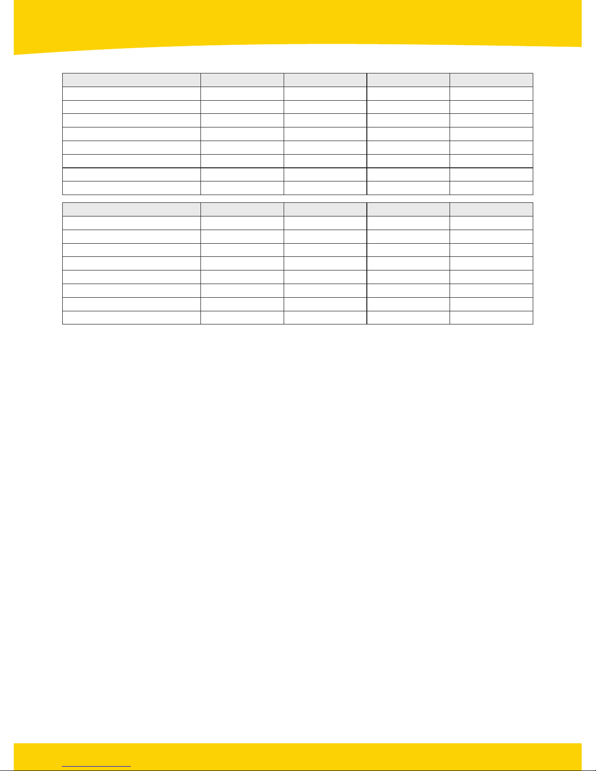
1. Electrical Performance Parameters
01
www.solarland.com.au
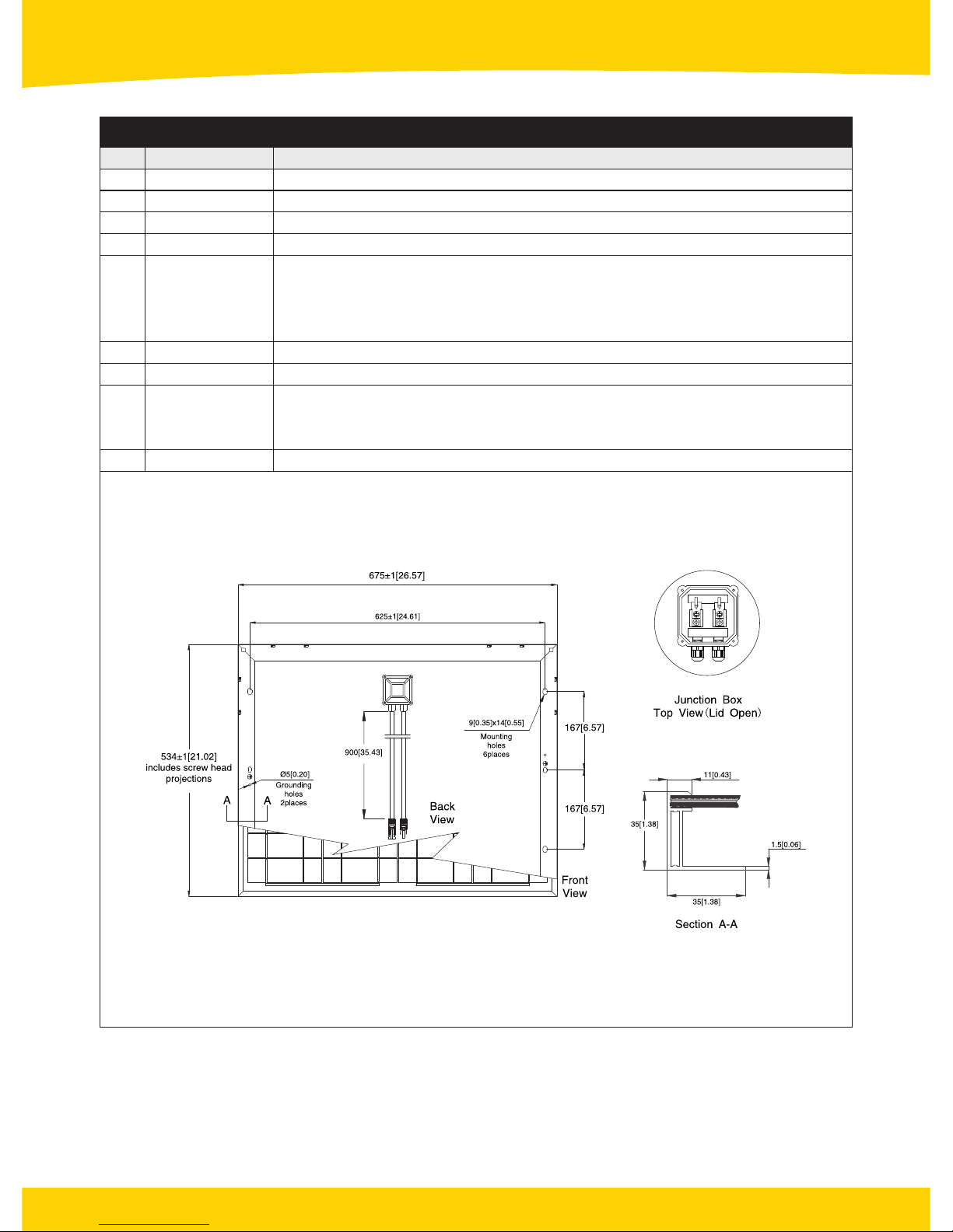
SLPXXX-24V (where XXX is directly related to module’s rated power) series solar modules are made of 72pcs
156×78mm mono crystalline solar cell in series with high efficiency, high transmission rate, low iron tempered
glass, anti-aging EVA, high flame resistant TPT laminate, and anodized aluminium alloy frames. Wuxi Tianran
Photovoltaic Co., Ltd. (SOLARLAND) modules have long life, easy installation, high wind and hail impact
resistance and many other advantages.
SOLARLAND modules are made according to international standards and have passed several third party test
centre’s examination for certification.
SLPXXX-24V series solar modules mainly include 120Watt, 125Watt, 130Watt, 135Watt, 140Watt.
Value Parameters
Max Power (Pmax)
Operating Voltage (Vmp)
Operating Current (Imp)
Open-Circuit Voltage (Voc)
Short-Circuit Current (Isc)
Maximum System Voltage
Output Tolerance
Maximum Series Fuse Rating
SLP010-12V
10W
17.0V
0.58A
21.6V
0.68A
±3%
1000V
1 A
SLP015-12V
15W
17.2V
0.87A
21.6V
0.96A
±3%
1000V
2 A
SLP020-12V
20W
17.2V
1.16A
21.6V
1.31A
±3%
1000V
2 A
SLP025-12V
25W
17.2V
1.45A
21.6V
1.60A
±3%
1000V
2 A
SLP030-12V
30 W
17.2 V
1.75 A
21.2 V
1.90A
±3%
1000V
3A
Value Parameters
Max Power (Pmax)
Operating Voltage (Vmp)
Operating Current (Imp)
Open-Circuit Voltage (Voc)
Short-Circuit Current (Isc)
Maximum System Voltage
Output Tolerance
Maximum Series Fuse Rating
SLP035-12V
35 W
18.1 V
1.94 A
21.9 V
2.09 A
±3%
1000V
3A
SLP040-12V
40 W
17.2 V
2.33 A
21.6 V
2.55 A
±3%
1000V
4 A
SLP045-12V
45 W
18.0 V
2.50 A
21.8 V
2.73 A
±3%
1000V
4 A
SLP050-12V
50 W
17.4 V
2.88 A
21.2 V
3.15 A
±3%
1000V
5A
Value Parameters
Max Power (Pmax)
Operating Voltage (Vmp)
Operating Current (Imp)
Open-Circuit Voltage (Voc)
Short-Circuit Current (Isc)
Maximum System Voltage
Output Tolerance
Maximum Series Fuse Rating
SLP055-12V
55 W
17.9 V
3.08 A
21.7V
3.38 A
±3%
1000V
5A
SLP060-12V
60 W
17.2 V
3.49 A
21.2 V
3.81 A
±3%
1000V
6 A
SLP065-12V
65 W
17.7 V
3.68 A
21.6 V
4.01 A
±3%
1000V
6 A
SLP070-12V
70 W
18.1 V
3.87A
21.9 V
4.18 A
±3%
1000V
6 A
NOTE: All technical data at standard test condition (E=1000W/m² TC=25°C Am=1.5)