1
Contents
1. Short description...............................................................................................................................................................2
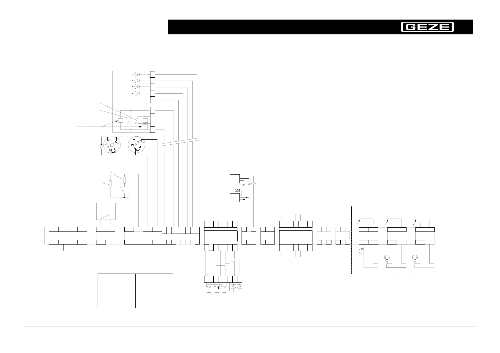
2. Layout plan..........................................................................................................................................................................3
3.1 Mains connection ...........................................................................................................................................................4
3.2 Connection of the battery ...........................................................................................................................................4
3.3 Connection of smoke and heat difference sensor...........................................................................................4
3.4 Operation without smoke or heat difference senosr.......................................................................................4
3.5 Connection of SHE switch FT4/24V DC - VdS....................................................................................................5
3.6 Connection of fire alarm system (BMS) / remote trip release .....................................................................5
3.7 Operation without central fire alarm system (BMS) / remote trip release.............................................5
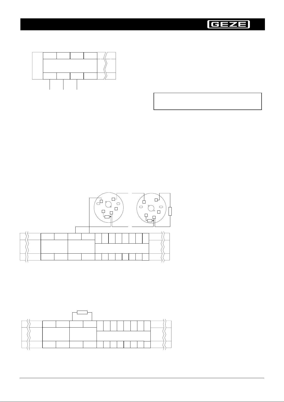
4.1 Connection of motors...................................................................................................................................................6
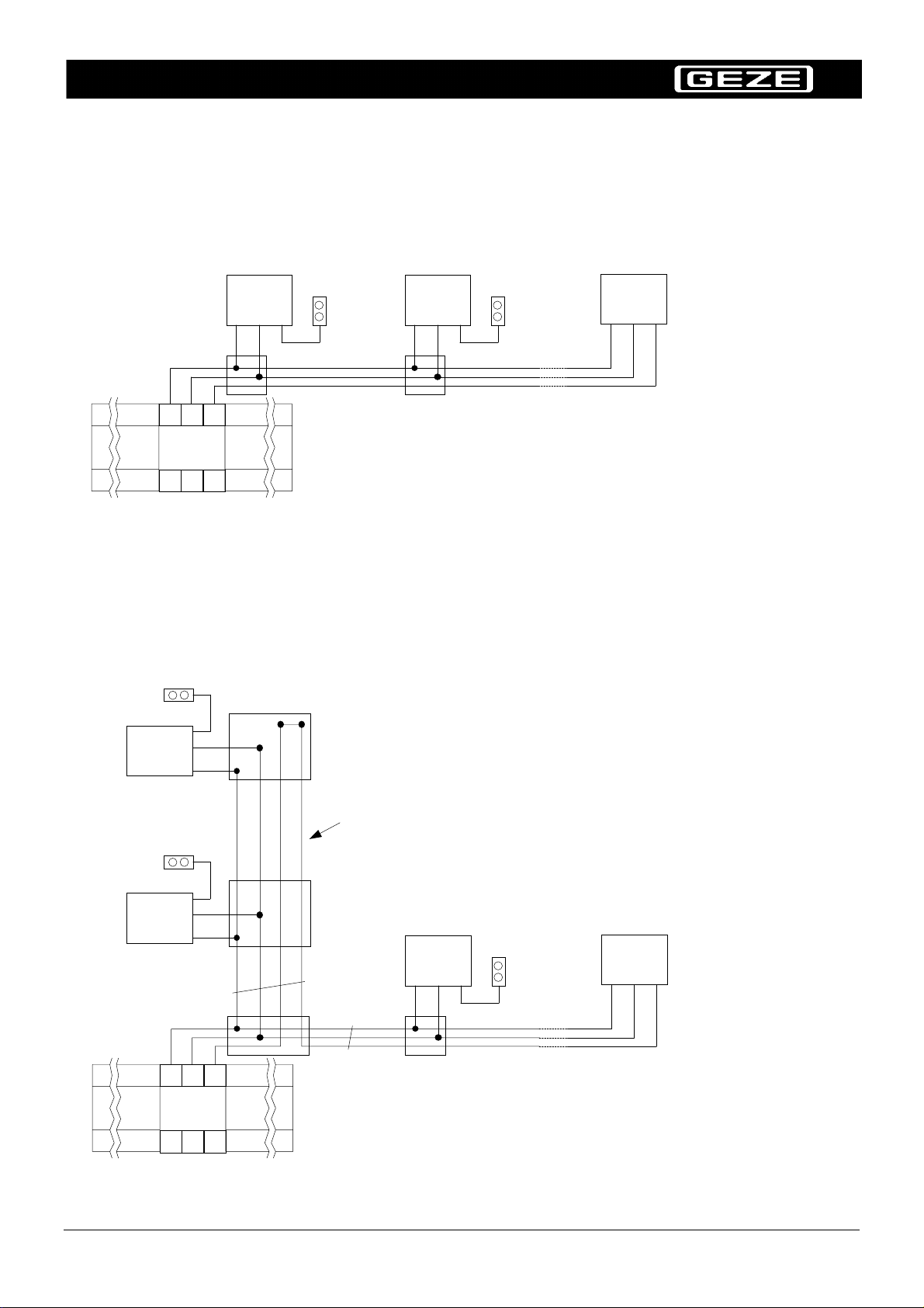
4.1.1 Linear, 1 cable section..............................................................................................................................................6
4.1.2 Branched, 2 or more cable sections...................................................................................................................6
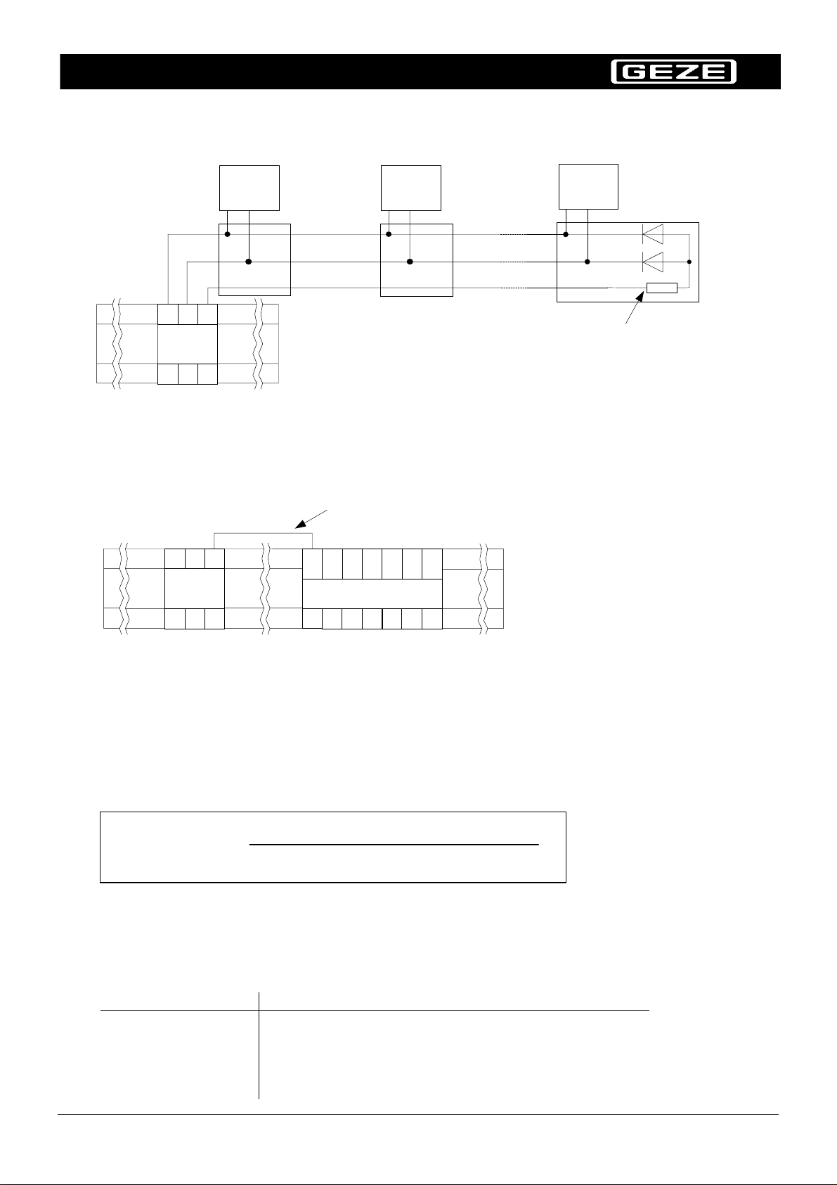
4.1.3 Connections of motors without integrated line monitoring.....................................................................7
4.1.4 Unused motor group..................................................................................................................................................7
4.2 Motor lines.........................................................................................................................................................................7
4.2.1 Calculation of the cross-sections for motor lines........................................................................................7
4.2.2 Examples for max. line lengths in [m]................................................................................................................7
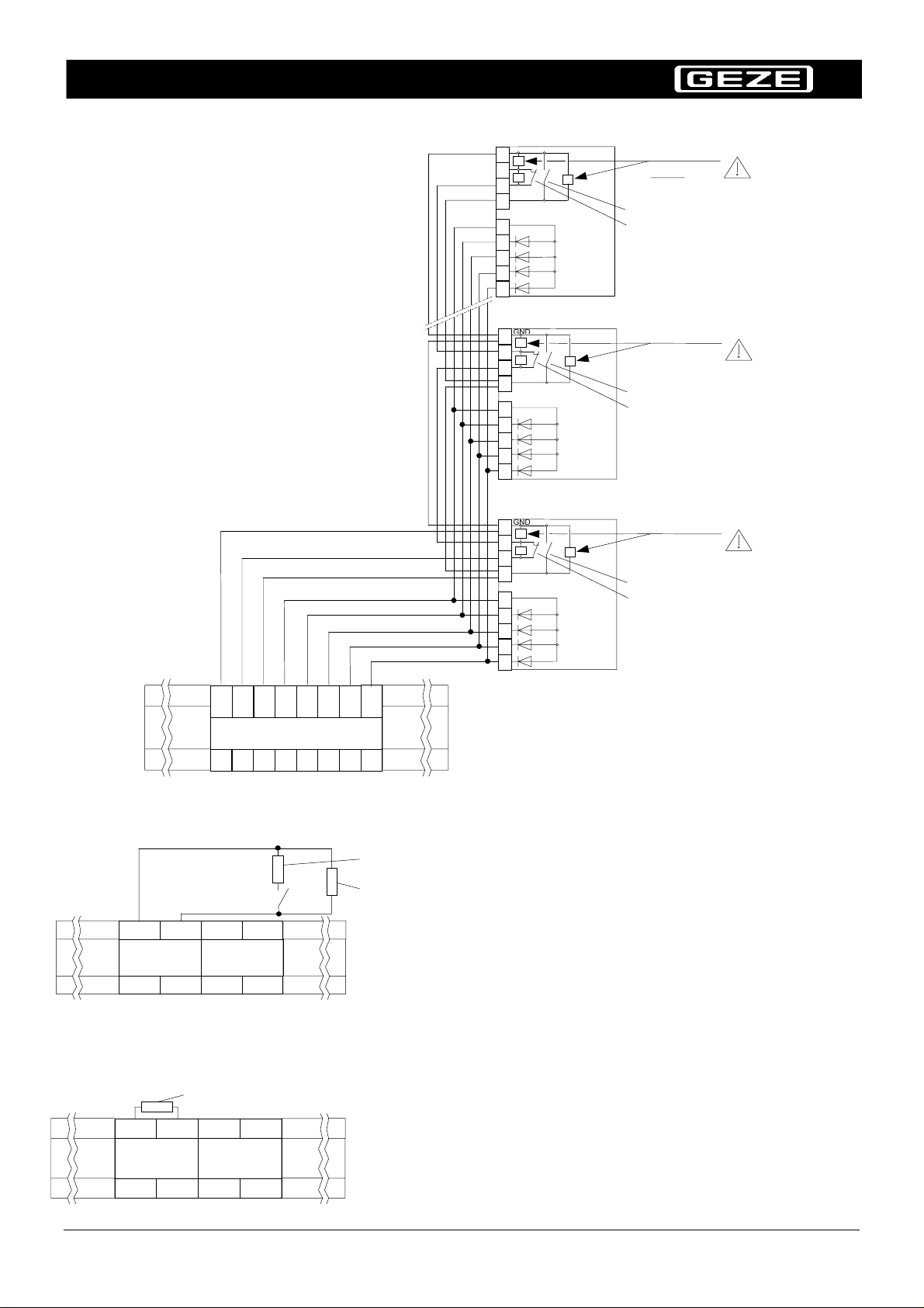
5.1 Connection of ventilator switch...............................................................................................................................8
5.2 Connection of several ventilator switches per ventilator group................................................................9
5.2.1 Ventilator switch LTA-230.......................................................................................................................................9
6 Connection of timer.........................................................................................................................................................10
6.1 Timer per ventilator group........................................................................................................................................10
6.2. Several ventilator groups with 1 timer...............................................................................................................10
7.1 Connection of rain/wind control unit ...................................................................................................................11
7.2 Connection of several emergency power control units E260N to 1 rain/wind control unit..........11
8.1 Potential-free signaling contacts (optional)......................................................................................................12
8.2 Connection with externals supply voltage........................................................................................................12
8.3 Connection of a sounder with internal supply voltage (max.30mA)......................................................12
Refer to cable layout 37101-9-0951
Observe the corresponding operating instructions!
118533-4 Connection Schema Emergency Power Supply System E260 N2/1 to N12/2-24V DC