Elsner KNX PS640-IP 2U User manual
08.06.2021
Technische Änderungen und Irrtümer vorbehalten. / Technical changes and errors excepted.
Elsner Elektronik GmbH • Sohlengrund 16 • 75395 Ostelsheim • Deutschland • www.elsner-elektronik.de • Service: +49 (0) 7033 / 30945-250
D
KNX PS640-IP 2U
70147
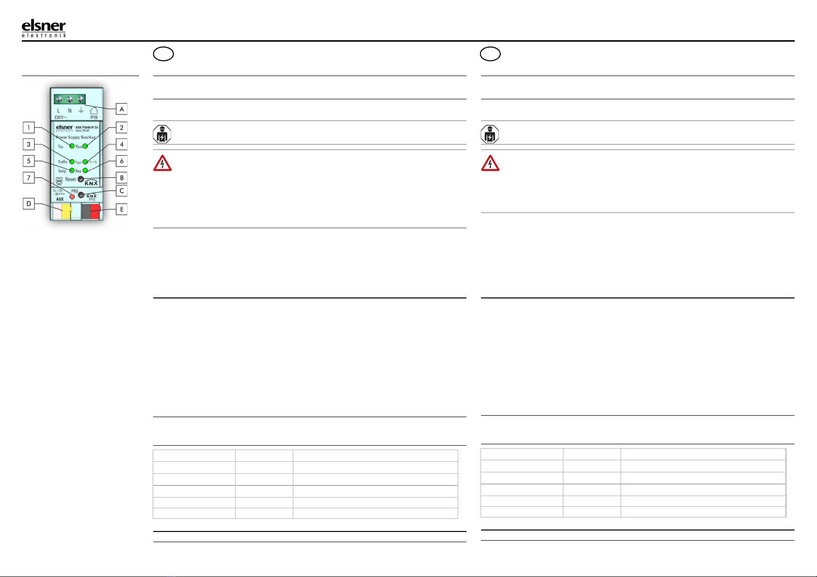
Fig. 1
DE Aufbau des Geräts
1 Eingangsspannung VIN
2 Busspannung VBUS
3 Telegrammverkehr
4 Ausgangsstrom IOUT
grün: IOUT < 640 mA
orange: IOUT ist 640…900 mA
rot: IOUT > 900 mA (Überlast)
5 Temperatur
grün: Temperatur ist 0…75 °C
rot: Temp. ist außerhalb dieses
Bereichs
6 KNX-Bus Reset
rot: Neustart der KNX-Linie wird
durchgeführt
7 Programmier-LED
rot: Programmier-Modus an
A Netzanschluss
B Resettaste
C Programmiertaste
D Hilfsspannungsanschluss
EKNXTPAnschluss
EN Device structure
1 Input voltage VIN
2 Bus voltage VBUS
3 Telegram traffic
4 Output current IOUT
green: IOUT < 640 mA
orange: IOUT is 640…900 mA
red: IOUT > 900 mA (Overload)
5 Temperature
green: Temperature is 0…75 °C
red: Temp. is out of this range
6 KNX bus reset
red: Restart of the KNX bus line
is running
7 Programming LED
red: Programming Mode active
A Supply voltage terminals
B Reset button
C Programming button
D Aux output connector
E KNX TP connector
Intelligente Spannungsversorgung KNX-Bus/Hilfsspannung
Installationshinweise
Sicherheits- und Gebrauchshinweise
Produkt-Handbuch und Produktdatei (ETS 5-Applikation) finden Sie auf der Homepage von
Elsner Elektronik unter www.elsner-elektronik.de im Menübereich „Service“ zum Download.
Installation, Prüfung, Inbetriebnahme und Fehlerbehebung dürfen nur von einer
autorisierten Elektrofachkraft durchgeführt werden.
GEFAHR!
Lebensgefahr durch elektrische Spannung (Netzspannung)!
Im Innern des Geräts befinden sich ungeschützte spannungsführende Teile.
• Untersuchen Sie das Gerät vor der Installation auf Beschädigungen. Nehmen Sie nur
unbeschädigte Geräte in Betrieb.
• Halten Sie die vor Ort geltenden Richtlinien, Vorschriften und Bestimmungen für die elektrische
Installation ein.
• Nehmen Sie das Gerät bzw. die Anlage unverzüglich außer Betrieb und sichern Sie sie gegen
unbeabsichtigtes Einschalten, wenn ein gefahrloser Betrieb nicht mehr gewährleistet ist.
Verwenden Sie das Gerät ausschließlich für die Gebäudeautomation und beachten Sie die Ge-
brauchsanleitung. Unsachgemäße Verwendung, Änderungen am Gerät oder das Nichtbeachten
der Bedienungsanleitung führen zum Erlöschen der Gewährleistungs- oder Garantieansprüche.
Betreiben Sie das Gerät nur als ortsfeste Installation, das heißt nur in montiertem Zustand und nach
Abschluss aller Installations- und Inbetriebnahmearbeiten und nur im dafür vorgesehenen Umfeld.
Für Änderungen der Normen und Standards nach Erscheinen der Bedienungsanleitung ist Elsner
Elektronik nicht haftbar.
Beschreibung
Die intelligente Spannungsversorgung KNX PS640-IP 2U mit erweiterter Diagnose- und
Alarmfunktion versorgt eine Linie des KNX-Bussystems mit 30 V DC und verfügt über einen zusätz-
lichen, unverdrosselten Spannungsausgang. Beide Ausgänge sind überlastsicher und kurzschluss-
fest. Betriebszustände von Gerät und KNX TP Linie sind an der LED-Anzeige ablesbar.
Die KNX TP Linie kann per Objekt und per Resettaste zurückgesetzt werden. Zur Diagnose stehen
Messwerte von KNX-Busspannung, Ausgangsstrom, Betriebstemperatur und Betriebszeiten (ge-
samt/ab letztem Startup) zur Verfügung. Per Alarm wird informiert, wenn ein Messwert seinen Nor-
malbereich oder einen vorher festgelegten Bereich verlassen hat. Insgesamt können bis zu acht ver-
schiedene Alarme konfiguriert werden.
Die KNX PS640-IP 2U kann ihre Info-Telegramme auf Anfrage, regelmäßig und nach bestimmten
Ereignissen verschicken. Details (Anzahl/Dauer) zu Kurzschluss, Überlast sowie vorher konfigurier-
ten Schwellenwert-Überschreitungen sind zugänglich. Nach Rückkehr zum Normalbetrieb, Geräte-
neustart, KNX-Bus-Neustart werden Info-Telegramme versendet. Heartbeat-Telegramme signali-
sieren eine einwandfreie Funktion.
Lieferumfang
• Spannungsversorgung
• KNX-Klemme und Hilfsspannungsklemme (weiß/gelb)
Tasten und LEDS
Installation
Montageort und Vorbereitung
• Installation nur in trockener Umgebung. Gerät vor Feuchtigkeit, Schmutz und Beschädigung
schützen
Eingangsspannung VIN [off] VIN ist 195…265 V AC
Eingangsspannung VIN rot VIN ist außerhalb dieses Bereichs
Busspannung VBUS grün VBUS ist 28…31 V DC
Busspannung VBUS rot VBUS ist außerhalb dieses Bereichs
Telegrammverkehr grün (blinkend) Telegrammverkehr < 80 %
Telegrammverkehr rot Telegrammverkehr > 80 %
Intelligent Power Supply KNX bus/Auxiliary Voltage
Installation instructions
Safety and operating instructions
Product manual and product file (ETS 5 application) can be downloaded from the Elsner Elek-
tronik website on www.elsner-elektronik.de in the “Service” menu.
Installation, testing, operational start-up and troubleshooting should only be performed by
an authorised electrician.
DANGER!
Risk to life from live voltage (mains voltage)!
There are unprotected live components inside the device.
• Inspect the device for damage before installation. Only put undamaged devices into operation.
• Comply with the locally applicable directives, regulations and provisions for electrical installation.
• Immediately take the device or system out of service and secure it against unintentional switch-
on if risk-free operation is no longer guaranteed.
Use the device exclusively for building automation and observe the operating instructions. Impro-
per use, modifications to the device or failure to observe the operating instructions will invalidate
any warranty or guarantee claims.
Operate the device only as a fixed-site installation, i.e. only in assembled condition and after con-
clusion of all installation and operational start-up tasks, and only in the surroundings designated
for it.
Elsner Elektronik is not liable for any changes in norms and standards which may occur after publi-
cation of these operating instructions.
Description
The intelligent Power Supply KNX PS640-IP 2U with extensive diagnostic and alarm functio-
nality powers one line of a KNX system with 30 V DC and has an additional unchoked voltage out-
put to provide auxiliary power. Both outputs are overload-proof and short circuit protected. LEDs
indicate the state of the power supply and the KNX TP line.
The KNX TP line can be reset via object and via push-button press. For diagnostics, input state, KNX
bus voltage, output current, device temperature and times of operation (total/since last startup) are
monitored. Alarms inform about measurement values leaving the normal working range or the con-
figured threshold range. Up to eight different alarms can be pre-defined.
KNX PS640-IP 2U is able to send info telegrams on request, periodically and after certain events.
Details (number/duration) on output failures like short circuits, overloads and over-threshold events
are accessible. Info telegrams also inform on returning to normal working condition after device
startup, after a KNX bus restart and after a short circuit. Heartbeat telegrams indicate proper func-
tioning.
Scope of delivery
• Power Supply System
• KNX terminal and auxiliary voltage terminal (white/yellow)
Buttons and LEDs description
Installation
Installation location and preparation
• Installation only in dry locations. Protect the device from moisture, dirt and damage
• Accessibility of the device for operation and visual inspection must be provided
• The housing of the device must not be opened
Input voltage VIN [off] VIN is 195…265 V AC
Input voltage VIN red VIN is out of this range
Bus voltage VBUS green VBUS is 28…31 V DC
Bus voltage VBUS red VBUS is out of this range
Telegram traffic green (blinking) Telegram traffic < 80 %
Telegram traffic red Telegram traffic > 80 %
EN

08.06.2021
Technische Änderungen und Irrtümer vorbehalten. / Technical changes and errors excepted.
Elsner Elektronik GmbH • Sohlengrund 16 • 75395 Ostelsheim • Deutschland • www.elsner-elektronik.de • Service: +49 (0) 7033 / 30945-250
Versorgung: Power input:
230V ±15%,50Hz Netzspannung Mains voltage
1.2 W Verlustleistung (offen) Leakage loss (open-circuited)
4.7 W Verlustleistung (normal) Leakage loss (normal)
23 W Leistungsbedarf (normal) Power consumption (normal)
42 W Leistungsbedarf (max., Überlast) Power consumpt. (max., overload)
Gehäuse: Housing:
RAL 9018 Kunststoffgehäuse PA66, Gehäusefarbe weiß Plastic PA66 housing, Housing colour white
94 mm × 36 mm × 71 mm Maße (H × B × T), 2 TE zu je 18 mm Dimensions (H × W × D), 2 modules at 18 mm
(TH35) Montage (IEC60715) 35 mm-Schiene (DIN) Mounting (IEC60715) 35 mm top-hat rail
0.3…2.5 mm² Netzanschluss Schraubklemmen (max. Anzugsdrehm. 0.4 Nm) Mains voltage connection Screw terminals (max. torque 0.4 Nm)
Ø 0.6...0.8 mm KNX Bus-Anschluss KNX-Klemme (rot/schwarz), schraubenlos, für einadriges Kabel KNX bus connection KNX TP connector (red/black), screwless, for single-core cable
Ø 0.6...0.8 mm AUX (Hilfsspannungs)-Anschluss KNX-Klemme (weiss/gelb), schraubenlos, für einadriges Kabel AUX output connection KNX TP connector (white/yellow), screwless, for single-core cable
185 g Gewicht Weight
Umgebungsbedingungen: Environmental conditions:
-5…+45 °C Arbeitstemperatur Operating temperature
-20…+70 °C Lagertemperatur Storage temperature
5...93 % Umgebende Feuchte (nicht kondensierend) Ambient humidity (non-condensing)
Ausgangsleistung: Power output:
28…31 V SELV KNX-Busspannung KNX output voltage
28…31 V SELV AUX-Hilfsspannung AUX output voltage
640 mA Nennstrom Rated current
1.2 A Maximalstrom (gesamt) Maximum current (total output)
> 100 ms Überbrückungszeit bei Netzausfall Mains failure bridging time
82 % Effizienz bei Normallast Efficiency at nominal load
10 s Unterbrechungszeit nach Ausfall Disconnection time after failure
Elektrische Sicherheit: Electrical safety:
2 Verschmutzungsgrad (IEC60664) Pollution degree (IEC60664)
II Schutzklasse (IEC61140) Protection class (IEC61140)
III Überspannungskategorie (IEC60664) Overvoltage category (IEC60664)
DE Installationsschema
EN Installation scheme
Fig. 2
• Der Zugang zum Gerät muss für Bedienung und Inspektion stets gewährleistet sein
• Das Gehäuse des Geräts darf nicht geöffnet werden
• Zur Montage ein geeignetes Werkzeug nach IEC60715 verwenden
• Installation nur in Verteilerkästen oder geschlossenen Gehäusen. Installation nur auf geeigneter
DIN-Hutschiene (TH35). Stromführende Teile müssen vollständig abgedeckt werden. Die Abde-
ckung darf nicht ohne Hilfe eines Werkzeugs zu entfernen sein. Der Berührschutz muss durch den
Schaltschrank gewährleistet sein
Anschluss
Die KNX-Buslinie, wie für alle üblichen KNX-Anschlüsse, mit abisoliertem KNX-Buskabel und KNX-
TP-Klemme anschließen. Beim Anschließen nicht die elektrische Isolationen beschädigen
Wartung
Das Gerät ist wartungsfrei. Wenn nötig, das Gerät mit einem trockenen Tuch reinigen
Entsorgung
Das Gerät muss nach dem Gebrauch entsprechend den gesetzlichen Vorschriften entsorgt bzw. der
Wiederverwertung zugeführt werden. Nicht über den Hausmüll entsorgen!
Technische Daten
Das Produkt ist konform mit den Bestimmungen der EU-Richtlinien.
• For mounting use an appropriate equipment according to IEC60715
• Installation only in distribution boards and enclosed housings. Installation only on a 35 mm DIN
rail (TH35). Terminals and metal parts under current must be completely covered. It must be not
possible to remove the cover without aid of a tool. Contact protection must be provided through
the control cabinet
Connection
Connect the KNX bus line as for common KNX bus connections with a KNX bus cable, to be stripped
and plugged into the KNX TP connector. Do not damage electrical insulations when connecting
Maintenance
The device needs no maintenance. If necessary, the device can be cleaned with a dry cloth
Disposal
After use, the device must be disposed of or recycled in accordance with the legal regulations. Do
not dispose of it with the household waste!
Technical data
The product conforms to the conditions of the EU Directives.
Other Elsner Power Supply manuals


