1
1
2
V
D
C
M
A
X
1
0
A
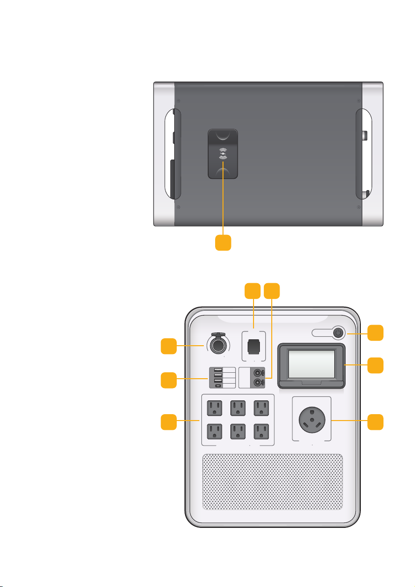
12VDC
MAX 30A
5V 2.4A
5V 2.4A
QC 3.0
PD60W
12VDC
2A
ON/OFF
AC OUTPUT
25AMAX
AC OUTPU T MAX 20A
1.0 Introduction
Thank you very much for purchasing the
Hysolis Apollo-5K unit! We designed this product
to help grant you energy independence. We have
the utmost confidence in this product’s
performance and quality. Please feel free to
contact us at Hysolis.com if you have any
questions. Enjoy using your Hysolis Apollo 5K,
and may it positively aect your future
endeavors!
The product has the following features:
• Dual-CPU Intelligent Control Technology manages energy input/output
• High-frequency pure sine wave output is clean and reliable for any load
• Wide input voltage range and consistent voltage output
• Three programmable working modes prioritize dierent energy needs:
• UPS mode: Utility Power first, a.k.a. “Pass-through AC Power”
• AC Fast Charge (AC F.C.) mode: 120V AC power Fast Charge,
500W-3,000W programmable
• Battery First mode: The solar charges the battery and grid. AC Power is
only used if battery is almost empty.
• Intelligent MPPT solar controller features over-charge & over-discharge
protection, current limiting charging, and multiple other safety protections
• Battery over-voltage and low-voltage protection, overload protection, short
circuit protection, over-temperature and under-temperature protection.
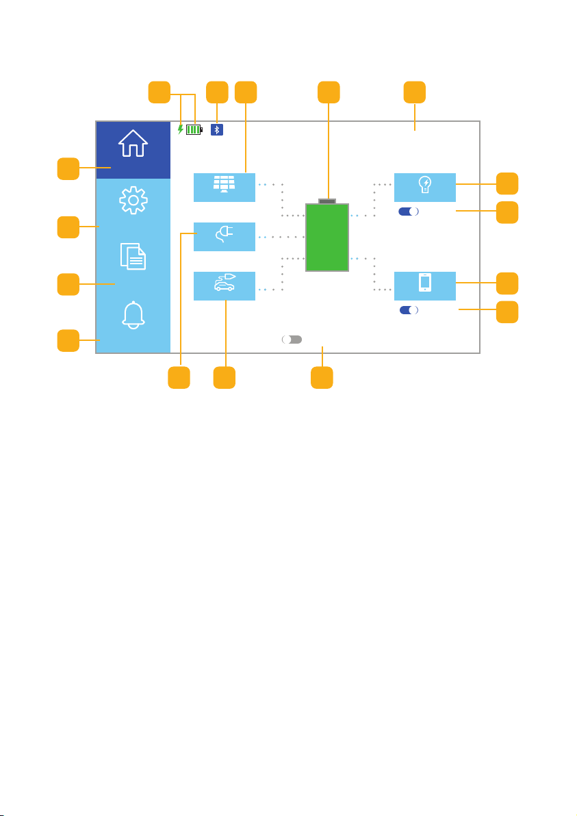
• A 4.3” touchscreen shows real-time running statuses at-a-glance
• Remote monitoring & control
• Compact and modular unit design for portability
• Smart Fan Control keeps the unit cool, safe, and reliable
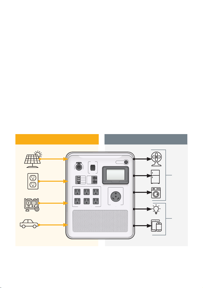
• Multiple output power supply (120VAC/3000W, 12VDC/600W, 5VDC/120W)