Solar Stik 24VDC HyPR 3000 Installation instructions

|1November 2023 |Solar Stik®, Inc.
24VDC HyPR 2500 Operator and Maintenance Manual
Operator and Maintenance Manual
for the
24VDC HyPR 2500
Updated:20231116
DISTRIBUTION STATEMENT A. Approved for public release; distribution is unlimited.
P/N 20-0104050

November 2023 |Solar Stik®, Inc.2 |
24VDC HyPR 2500 Operator and Maintenance Manual
Contents
GENERAL INFORMATION, EQUIPMENT DESCRIPTION, AND THEORY OF OPERATION
Introduction . . . . . . . . . . . . . . . . . . . . . . . . . . . . . . . . . . . . . . . . . . . . . . . . . . . . . 5
Requirements for HyPR Operation . . . . . . . . . . . . . . . . . . . . . . . . . . . . . . . . . . . . . . . . .5
HyPR 2500 Capabilities and Controls . . . . . . . . . . . . . . . . . . . . . . . . . . . . . . . . . . . . . . . 6
User Control Functions . . . . . . . . . . . . . . . . . . . . . . . . . . . . . . . . . . . . . . . . . . . . . . . 6
Data Management . . . . . . . . . . . . . . . . . . . . . . . . . . . . . . . . . . . . . . . . . . . . . . . . . . 6
Theory of Operation
General Information . . . . . . . . . . . . . . . . . . . . . . . . . . . . . . . . . . . . . . . . . . . . . . . . . 8
AC Functions . . . . . . . . . . . . . . . . . . . . . . . . . . . . . . . . . . . . . . . . . . . . . . . . . . . . . 8
Charging . . . . . . . . . . . . . . . . . . . . . . . . . . . . . . . . . . . . . . . . . . . . . . . . . . . . . 8
Inverting . . . . . . . . . . . . . . . . . . . . . . . . . . . . . . . . . . . . . . . . . . . . . . . . . . . . . . 8
DC Functions . . . . . . . . . . . . . . . . . . . . . . . . . . . . . . . . . . . . . . . . . . . . . . . . . . . . .9
Load Prioritization . . . . . . . . . . . . . . . . . . . . . . . . . . . . . . . . . . . . . . . . . . . . . . . . . . 9
Modes of Operation . . . . . . . . . . . . . . . . . . . . . . . . . . . . . . . . . . . . . . . . . . . . . . . . 10
Selecting an AC Power Source . . . . . . . . . . . . . . . . . . . . . . . . . . . . . . . . . . . . . . . . . . 11
Battery Current Requirements for HyPR AC Output . . . . . . . . . . . . . . . . . . . . . . . . . . . . . . 11
Temperature-dependent Power Processing. . . . . . . . . . . . . . . . . . . . . . . . . . . . . . . . . . . 12
Derating Specications . . . . . . . . . . . . . . . . . . . . . . . . . . . . . . . . . . . . . . . . . . . . . 12
How to Minimize Derating . . . . . . . . . . . . . . . . . . . . . . . . . . . . . . . . . . . . . . . . . . . . 12
Important Safety Information and Instructions . . . . . . . . . . . . . . . . . . . . . . . . . . . . . . . . . 13
Safety Information Labels . . . . . . . . . . . . . . . . . . . . . . . . . . . . . . . . . . . . . . . . . . . . 13
Fire Hazard . . . . . . . . . . . . . . . . . . . . . . . . . . . . . . . . . . . . . . . . . . . . . . . . . . . 14
Recommended Fire Extinguisher . . . . . . . . . . . . . . . . . . . . . . . . . . . . . . . . . . . . . . . . 14
Electric Shock Hazard. . . . . . . . . . . . . . . . . . . . . . . . . . . . . . . . . . . . . . . . . . . . . . 15
Environmental and Handling Precautions . . . . . . . . . . . . . . . . . . . . . . . . . . . . . . . . . . . . 16
Water . . . . . . . . . . . . . . . . . . . . . . . . . . . . . . . . . . . . . . . . . . . . . . . . . . . . . . 16
Impact . . . . . . . . . . . . . . . . . . . . . . . . . . . . . . . . . . . . . . . . . . . . . . . . . . . . . . 16
Dust/Foreign Object Intrusion . . . . . . . . . . . . . . . . . . . . . . . . . . . . . . . . . . . . . . . . . . 16
Heat . . . . . . . . . . . . . . . . . . . . . . . . . . . . . . . . . . . . . . . . . . . . . . . . . . . . . . . 16
The Inter-Connect System . . . . . . . . . . . . . . . . . . . . . . . . . . . . . . . . . . . . . . . . . . . . 17
24VDC Linear Inter-Connect Cable . . . . . . . . . . . . . . . . . . . . . . . . . . . . . . . . . . . . . . . 18
The Standard Inter-Connect Plug . . . . . . . . . . . . . . . . . . . . . . . . . . . . . . . . . . . . . . . . 18
EQUIPMENT DESCRIPTION
Introduction . . . . . . . . . . . . . . . . . . . . . . . . . . . . . . . . . . . . . . . . . . . . . . . . . . . . 19
AC Power Input Port . . . . . . . . . . . . . . . . . . . . . . . . . . . . . . . . . . . . . . . . . . . . . . . . 20
Connecting Generators to HyPR . . . . . . . . . . . . . . . . . . . . . . . . . . . . . . . . . . . . . . . . . 20
24 VDC IN/OUT Ports . . . . . . . . . . . . . . . . . . . . . . . . . . . . . . . . . . . . . . . . . . . . . . . 21
120 VAC OUTPUT Ports . . . . . . . . . . . . . . . . . . . . . . . . . . . . . . . . . . . . . . . . . . . . . . 22
Vents . . . . . . . . . . . . . . . . . . . . . . . . . . . . . . . . . . . . . . . . . . . . . . . . . . . . . . . . 22
24 VDC HyPR Faceplate . . . . . . . . . . . . . . . . . . . . . . . . . . . . . . . . . . . . . . . . . . . . . . 23
AC Interface . . . . . . . . . . . . . . . . . . . . . . . . . . . . . . . . . . . . . . . . . . . . . . . . . . . . 24
AC Input Current Limit Switch. . . . . . . . . . . . . . . . . . . . . . . . . . . . . . . . . . . . . . . . . . 24
Breakers / Switches . . . . . . . . . . . . . . . . . . . . . . . . . . . . . . . . . . . . . . . . . . . . . . . . 24
DC Interface . . . . . . . . . . . . . . . . . . . . . . . . . . . . . . . . . . . . . . . . . . . . . . . . . . . . 25
Battery Voltage . . . . . . . . . . . . . . . . . . . . . . . . . . . . . . . . . . . . . . . . . . . . . . . 25

|3November 2023 |Solar Stik®, Inc.
24VDC HyPR 2500 Operator and Maintenance Manual
Current . . . . . . . . . . . . . . . . . . . . . . . . . . . . . . . . . . . . . . . . . . . . . . . . . . . 25
Connecting Generators to HyPR . . . . . . . . . . . . . . . . . . . . . . . . . . . . . . . . . . . . . . . . . 26
Operator Instructions
HyPR Setup and Operation . . . . . . . . . . . . . . . . . . . . . . . . . . . . . . . . . . . . . . . . . . . . 27
Navigating DC User Interface Menus . . . . . . . . . . . . . . . . . . . . . . . . . . . . . . . . . . . . . . 28
Monitoring the Battery . . . . . . . . . . . . . . . . . . . . . . . . . . . . . . . . . . . . . . . . . . . . . . 28
BATTERY MONITOR . . . . . . . . . . . . . . . . . . . . . . . . . . . . . . . . . . . . . . . . . . . . . . . . 29
Battery Voltage . . . . . . . . . . . . . . . . . . . . . . . . . . . . . . . . . . . . . . . . . . . . . . . 29
Current . . . . . . . . . . . . . . . . . . . . . . . . . . . . . . . . . . . . . . . . . . . . . . . . . . . 29
Power . . . . . . . . . . . . . . . . . . . . . . . . . . . . . . . . . . . . . . . . . . . . . . . . . . . . 29
Consumed Amp-hours . . . . . . . . . . . . . . . . . . . . . . . . . . . . . . . . . . . . . . . . . . . 29
State-of-charge . . . . . . . . . . . . . . . . . . . . . . . . . . . . . . . . . . . . . . . . . . . . . . . 29
Synchronizing the Battery Monitor. . . . . . . . . . . . . . . . . . . . . . . . . . . . . . . . . . . . . . . . 30
Synchronizing Issues . . . . . . . . . . . . . . . . . . . . . . . . . . . . . . . . . . . . . . . . . . . . . . 30
SOC Display Options. . . . . . . . . . . . . . . . . . . . . . . . . . . . . . . . . . . . . . . . . . . . . . . . 30
Historical Data . . . . . . . . . . . . . . . . . . . . . . . . . . . . . . . . . . . . . . . . . . . . . . . . . . 31
Maintenance
Preventive Maintenance Checks and Services (PMCS) . . . . . . . . . . . . . . . . . . . . . . . . . . . . 32
HyPR 2500 Air Intake Filter Maintenance* . . . . . . . . . . . . . . . . . . . . . . . . . . . . . . . . . . . 32
Water Intrusion Remediation . . . . . . . . . . . . . . . . . . . . . . . . . . . . . . . . . . . . . . . . . . . 33
Transporting the HyPR 2500 . . . . . . . . . . . . . . . . . . . . . . . . . . . . . . . . . . . . . . . . . . . 33
TECHNICAL SPECIFICATIONS
ABOUT SOLAR STIK, INC.
Contact . . . . . . . . . . . . . . . . . . . . . . . . . . . . . . . . . . . . . . . . . . . . . . . . . . . . . 35

November 2023 |Solar Stik®, Inc.4 |
24VDC HyPR 2500 Operator and Maintenance Manual
List of Figures
Figure 1. Schematized power ow from a top-down view of the interior of the HyPR 2500 ........................................... 7
Figure 2. Using the HyPR 2500 in Hybrid Model............................................................................................................ 12
Figure 3. Using the HyPR 2500 in UPS Model ............................................................................................................... 12
Figure 4. Using HyPR in Power Conditioning Model...................................................................................................... 13
Figure 5. Using HyPR in Scavenge Model...................................................................................................................... 13
Figure 6. Using HyPR in Inverter Mode .......................................................................................................................... 14
Figure 7. Linear Inter-Connect Plug................................................................................................................................ 23
Figure 8. Inter-Connect Plug .......................................................................................................................................... 23
Figure 9. 24 VDC HyPR 2500 connections..................................................................................................................... 24
Figure 10. The HyPR 2500 I-Plate .................................................................................................................................. 25
Figure 11. HyPR 2500 AC power input port................................................................................................................... 26
Figure 12. HyPR 2500 solar input port ........................................................................................................................... 26
Figure 13. HyPR 2500 DC power scavenging port......................................................................................................... 27
Figure 14. HyPR Expander Expander Pak / ESM connection port ................................................................................ 28
Figure 15. HyPR 24 VDC input / output ports ................................................................................................................ 29
Figure 16. HyPR 120 VAC output ports.......................................................................................................................... 29
Figure 18. Expander Pak generator communications ports........................................................................................... 30
Figure 17. HyPR 2500 cooling vents .............................................................................................................................. 30
Figure 19. 24 VDC HyPR 2500 Faceplate ...................................................................................................................... 31
Figure 20. HyPR 2500 DC Interface ............................................................................................................................... 33
Figure 23. AC Input Control dial ..................................................................................................................................... 34
Figure 21. Generator mode control switches and LEDs................................................................................................. 34
Figure 22. Generator Status LED blinking pattern.......................................................................................................... 34
Figure 24. HyPR 2500 breakers...................................................................................................................................... 35
Figure 25. HyPR Inverter / AC OUTPUT status LED ...................................................................................................... 35
Figure 27. Connecting generators to HyPR.................................................................................................................... 36
Figure 26. Compatible generator options....................................................................................................................... 36
Figure 28. MEP-831A and MEP-802A Gen Comm Cable connections ......................................................................... 37
Figure 29. Defender 1 kW and Ranger 2 kW Gen Comm Cable connections ............................................................... 38
Figure 30. Connecting two 1 kW generators in parallel with the “Y” AC power cable................................................... 39
Figure 31. Navigating the DC Interface .......................................................................................................................... 41
Figure 32. Abbreviated HyPR DC Interface Menu Map.................................................................................................. 42
Figure 33. Cleaning/replacing HyPR 2500 air intake vent lter ...................................................................................... 43
Figure 35. HyPR human transportation. ......................................................................................................................... 44
Figure 34. Drain plug screw located under the TECH PORT.......................................................................................... 44
List of Tables
Table 1. Charge Status Indicator—LED Status............................................................................................................... 33
Revision History
Section Page(s) Description Date
First released as a PRELIMINARY DRAFT 16 Nov 2023

|5November 2023 |Solar Stik®, Inc.
24VDC HyPR 2500 Operator and Maintenance Manual
GENERAL INFORMATION, EQUIPMENT DESCRIPTION,
AND THEORY OF OPERATION
Introduction
A Hybrid Power Router (HyPR) is a power management device which processes and routes a variety
of power inputs to both DC and AC power outputs.
The HyPR is a modular, portable component of the Solar Stik Architecture and its design and exible
function affords the operator a “multi-tool” for applications demanding a singular power solution to
meet specic, and evolving, mission requirements.
Some features of the HyPR include:
• The ability to act as the primary power management device in a Hybrid Power System (HPS) or as
a supplemental power manager in AC, DC, or AC/DC systems.
• The ability to work in concert with additional power management devices when high-power or
individual control over multiple loads/voltages is required (eg. PRO-Verters).
• Support of simultaneous AC and DC outputs.
• Plug and play compatibility with the Solar Stik Inter-Connect circuit.
• Efcient management of available power to loads.
This manual provides operation and safety information for the HyPR 2500. The HyPR 2500 has been
designed specically to support Hybrid, UPS, and Power Conditioning.
When operating the HyPR within a system, consult the Faceplate and the System Manual for specic
operation guidelines.
Requirements for HyPR Operation
• Total power INPUT must exceed total power OUTPUT in any particular operation mode.
• The HyPR requires the presence of battery (DC bus) voltage to operate at its full rated power.
• Based on the application, the user must congure the system so there is “balanced” operation
between the HyPR’s internal functions.
HyPR 2500 accepts universal (120 VAC) single-phase AC input voltage, allowing connection to any
generator or grid AC power source. It is ideally suited for use where available AC power quality is
poor or AC line voltages vary. AC and DC cables for the HyPR are sold separately, as they must
match voltage type and associated current-conducting ability.

November 2023 |Solar Stik®, Inc.6 |
24VDC HyPR 2500 Operator and Maintenance Manual
HyPR 2500 Capabilities and Controls
The HyPR features specic capabilities for the system in which it is employed and, while many of the
circuits in the HyPR are fully automatic, outside user-established limits, not every HyPR feature may
be used in every application.
Most functions and modes are controlled by programmable settings at the User Interface(s).
• “Functions” are related to specic circuits or hardware in the HyPR.
• “Modes” refer to the operational employment of the HyPR circuits.
The faceplate contains breakers that control the input and output of both AC and DC power.
When the main power breaker switch is turned on:
• The HyPR DC INTERFACE will power up and report DC bus voltage and amperage data on the
home screen located on the front of the HyPR.
• The inverter (DC>AC) will be active, but only operational once the HyPR AC OUTPUT breaker is
engaged.
• The charger (AC>DC) will be active, but only operational once the HyPR AC INPUT breaker is
engaged.
Data Management
• The HyPR DC Interface provides basic DC circuit data, including ESM/bus voltage and net
current only when active ESMs are connected.
• If no ESMs are connected to the HyPR, then only the DC bus voltage is available from the HyPR
DC INTERFACE.
• DC bus voltage is the only accurately-reported metric from the HyPR DC INTERFACE when
ESMs are not connected.
User Control Functions

|7November 2023 |Solar Stik®, Inc.
24VDC HyPR 2500 Operator and Maintenance Manual
Figure 1. Schematized power ow from a top-down view of the interior of the HyPR 2500
Theory of Operation
The HyPR 2500 coordinates the support of AC and DC loads using power supplied from AC and/
or DC sources. Both AC and DC power sources energize the HyPR 2500 internal DC circuitry (DC
bus), or the “Inter-Connect” circuit. The presence of DC bus voltage (battery voltage) enables the full
function of the HyPR 2500 internal circuits. System voltage and net current can be monitored on the
DC User Interface.
A schematized illustration of the DC bus and its relationship to internal components, inputs and
outputs is shown below. The arrows indicate the ow of current in the circuits.
AC Input
24 VDC bus/Inter-Connect System
120 VAC,
60 Hz
24 VDC
Inter-Connect
Port
120 VAC
60 Hz
AC-
DC charger
Inverter
Breaker “location”
Direction of current ow
AC Output
Breaker “location”

November 2023 |Solar Stik®, Inc.8 |
24VDC HyPR 2500 Operator and Maintenance Manual
General Information
Circuit breakers on Faceplate are only for IN/OUT circuit limit protections. They are NOT “function
controls” or “function protections”.
The internal DC Bus is limited to 100 A total current ow. This may restrict some HyPR functionality
in certain operating modes.
Current ow on the DC bus is controlled by voltage. Power will always be prioritized to the loads and
will only cease when the voltage drops to low-voltage disconnects located within the inverter (AC
loads), the ESMs and DC Interface (DC loads).
24VDC IN/OUT ports operate directly from the internal DC bus. Power in/out of these ports will only
be reected in the “net” current on the display.
System recovery from overdischarged batteries is possible using AC power or alternative 24 VDC
power sources. System recovery using PV power is not an option.
Inverter “continuous AC power output” uctuates based on conditions such as temperature (heat
derating = efciency loss).
AC Functions
The HyPR employs two (2) separate AC functions that operate on the DC bus:
Charging
AC>DC converter provides up to 100 A to the DC bus (~2000 W).
Inverting
DC>AC inverter removes up to 9 A at 120 VAC from the internal DC bus (~1100 W).
When conguring the HyPR for use, it is important to understand how to establish balance between
the power available from sources and the power required by the loads.
When using AC power sources in Hybrid or UPS models, the AC INPUT setting must be set for the
following conditions:
• Continuity of AC load operation
• Battery charging
• Not to exceed the power output of the AC source
When small expeditionary generators are used, the HyPR can be used for dynamic loads that would
normally cause overloading of the generator.

|9November 2023 |Solar Stik®, Inc.
24VDC HyPR 2500 Operator and Maintenance Manual
DC Functions
The DC bus is effectively the nervous system of the HyPR. All HyPR functions are regulated directly
by the DC bus voltage. The DC bus voltage is functionally equivalent to the System battery voltage.
Direct connections to the DC bus can be made via the two (2) Inter-Connect ports. AC Input and AC
output ports are direct connections to the DC bus (See “Figure 1. Schematized power ow from a
top-down view of the interior of the HyPR 2500” on page 7).
DC power will ow into or out of the HyPR via the direct connections (Inter-Connect Port).
The indirect connections allow power to ow to the bus after being altered from its original form, for
example:
• AC power converted to 28.2 VDC
• Inverter converts energy stored in batteries to 120 VAC power output.
Load Prioritization
In every operation mode, the HyPR will prioritize power to the load. It executes functions based on
real-time operating conditions, which include:
• total power available at the INPUTS
• total power needed at the OUTPUTS
• battery SOC
• temperature
• user programming for special conditions
HyPRs can be used with grid-utility or generator AC power.
With load prioritization, the load will always be the rst to receive power. Any incoming power not
consumed by the load is stored in the batteries. Stored energy is for use to support loads when
these inputs are not available (e.g., grid failure, generator maintenance periods, etc.) and to reduce
reliance on fuel-powered generators.

November 2023 |Solar Stik®, Inc.10 |
24VDC HyPR 2500 Operator and Maintenance Manual
Energy Storage
Loads
AC
Hybrid Mode–The hybrid mode allows the use of a smaller generator based on average, continuous
total loads over a 24-hour period, versus a larger generator that will support “peak” loads, which are
usually momentary or short in duration:
• AC power generation source with ESMs
• DC power generation source with ESMs
• AC and DC power generation sources (combinations of the above) with ESMs
AC Power Limits
2000 W AC Input from source(s)
1100 W AC Output for loads
Modes of Operation
UPS Mode–The HyPR 2500 is capable of operating as an Uninterruptible Power Supply/Source,
providing instantaneous emergency power to a load in the event that primary power source fails. In
this mode, the HyPR 2500 will to provide power to the load until it can be turned off safely or until
primary power is restored. In this mode, power duration is limited to that contained in the ESM’s
connected to the HyPR 2500.
• AC utility / grid power sources with ESMs
• ESMs do not cycle
Figure 2. Using the HyPR 2500 in Hybrid Model
Grid or AC
Energy Storage
Loads
AC
AC Power Limits
2000 W AC Input from source(s)
1100 W AC Output for loads
Figure 3. Using the HyPR 2500 in UPS Model
There are several operational modes in which the HyPR may be congured, depending on the
application,
AC

|11November 2023 |Solar Stik®, Inc.
24VDC HyPR 2500 Operator and Maintenance Manual
Selecting an AC Power Source
HyPRs can be used with grid-utility or generator AC power sources, and can easily be congured to
work with the current limits of both the DC/AC power source circuits and the DC/AC load circuits.
Once the input and output power limits are congured, the HyPR regulates how much power is
delegated between these circuits, to prevent overload conditions.
Acceptable AC power sources for use with a single HyPR 2500 should provide the following:
• 1–2 kW of power
• Pure Sine Wave AC wave form output
When considering a fuel driven generator to pair with the HyPR, note that the maximum continuous
AC load should not exceed the maximum continuous output of the AC power generator (i.e.,
maximum load AC power requirement ≤ generator AC power output).
Battery Current Requirements for HyPR AC Output
A bank of batteries with the capacity to provide > 46 amps of current is required for the HyPR
(inverter) to operate at its full rated capacity (1100 W). Battery banks with smaller current capacity
are sufcient to power up the HyPR and support loads (AC and DC) that do not exceed the current
capacity of the connected batteries.
Connecting ESMs with an insufcient current capacity to the HyPR may result in the batteries being
charged or discharged too quickly causing the battery temperature to rise to a point that the battery
management system (BMS) disconnects the batteries from the system.
Note: The total Ah capacity of all connected ESMs must be programmed, (a setting in the DC
interface), for the HyPR DC interface to report accurately, the battery state of charge.

November 2023 |Solar Stik®, Inc.12 |
24VDC HyPR 2500 Operator and Maintenance Manual
Temperature-dependent Power Processing
The performance of all electric and electronic equipment varies with temperature with the rated
performance listed determined at standard testing conditions (77 ºF; 25 ºC). Generally performance
declines or “derates” when the equipment is operating in ambient temperatures colder or hotter than
STC; the hotter or colder the poorer the performance.
When the equipment itself generates heat, the temperature of the equipment will rise above ambient
(and STC) in direct proportion to power being processed. This too results in derating. Internal
thermostatic mechanisms are built into most equipment to reduce power processing in a heat-
dependent manner to lower heat and prevent damage. Power processing vs heat curves vary widely.
They HyPR contains two (2) major subcomponents, a charger and inverter. Both of these derate at
elevated temperatures but in a different manner. The inverter will provide full power up until a critical
temperature and then turn off, dropping the AC load then resume support of the AC load after the
inverter has cooled to a set point. The charger on the other hand, will reduce power processing at a
critical, dened temperature but continue to charge the batteries at a lower rate.
Heat absorbed by the sun (solar loading) also increases the internal temperature contributing to
temperature-dependent derating. Understanding how temperature-dependent derating affects HyPR
power processing will enable the Operator to make adjustments to ensure continuity of operations in
any environment.
Derating Specifications
The Inverter
• The inverter provides full power (1100 W) up to 86 ºF (30 ºC). It will decrease power output by
20% for each 18 ºF (10 ºC) increase over 86 ºF (30 ºC). The inverter will cease to process power
at 176 ºF (80 ºC), to self-protect, and will resume providing AC power after it cools to operating
temperature.
• Below 80 ºF (27 ºC), the HyPR can provide up to 1100 W continuous while not charging.
The Charger
• The HyPR charger provides full power (2000 W) up to ~158 ºF (30 ºC). At 158 ºF (70 ºC) it will
reduce power ~30% of full-rated power until it cools and resumes normal, full-rated output.
• Below 80 ºF (27 ºC), the HyPR can process around 2000 W continuous for battery charging (with
no loads connected).
How to Minimize Derating
• Do not overload the HyPR. Manage power processing demand by paying close attention to what
is “plugged in. Prioritize critical loads.
• Shade the HyPR 2500 to reduce solar loading. Solar Stik data indicates that solar loading of a
Pelican case can increase internal heat by ~40 ºF (~ 22 ºC) above ambient.
• Do not block airow into or out of the HyPR; give it space to breathe.
• Clean or replace the air intake lters regularly.

|13November 2023 |Solar Stik®, Inc.
24VDC HyPR 2500 Operator and Maintenance Manual
Important Safety Information and Instructions
This manual contains important instructions that must be followed during the setup and operation of
a the HyPR 2500. Read all instructions and information contained in this manual.
DO NOT begin assembly or use of the HyPR 2500 without rst reading and understanding this
manual.
While the HyPR 2500 designed for indoor/outdoor operation, the user interfaces (control panels)
must not be exposed to rain, snow, moisture, or liquids. Close and latch and/or lock the cases when
the components are unattended.
Exercise caution when handling or operating the HyPR 2500. Live power may be present.
Safety Information Labels
Your safety and the safety of others is very important.
Many important safety messages have been provided in this manual and directly on the System
components. Always read and obey all safety messages.
This is the safety alert symbol. This symbol is an alert to potential hazards that can cause
death or injury. All safety messages will follow the safety alert symbol and the word
“DANGER”, “WARNING”, or “CAUTION”. These words are dened as:
DANGER Indicates a hazardous situation which, if not avoided, will result in death or
serious injury.
WARNING Indicates a hazardous situation which, if not avoided, could result in death or
serious injury.
CAUTION Indicates a hazardous situation which, if not avoided, could result in minor or
moderate injury.
All safety messages will describe what the potential hazard is, how to reduce the chance of injury,
and what can happen if the instructions are not followed.

November 2023 |Solar Stik®, Inc.14 |
24VDC HyPR 2500 Operator and Maintenance Manual
Fire Hazard
Fire Types
Class A fire - Fires in ordinary combustibles such as wood, paper, cloth, trash, and plastics.
Class B fire - Fires in ammable liquids such as gasoline, petroleum, oil, and paint.
Class C fire - Fires involving energized electrical equipment such as motors, transformers, and
appliances. Remove the power source and the class C re becomes a class A or B re.
Recommended Fire Extinguisher
NSN 4210-00-548-7219 Fire Extinguisher, Carbon Dioxide, 10 lb
Carbon dioxide is a liqueed gas, which is highly effective ghting class B and C res. These
extinguishers are ideal for areas where contamination and/or cleanup are a concern, such as data
processing centers, labs, and telecommunication rooms.
Using the Fire Extinguisher
When using the extinguisher on a re, remember PASS:
Pull the pin.
Aim the nozzle or hose at the base of the re from a safe distance.
Squeeze the operating lever to discharge the re extinguishing agent.
Sweep the nozzle or hose from side to side until the re is out. Move forward or around the re as
the re diminishes.
Watch the area for reignition until the cause has been xed.
WARNING
Only CO2(carbon dioxide) re extinguishers should
be used with this equipment.
|15November 2023 |Solar Stik®, Inc.
24VDC HyPR 2500 Operator and Maintenance Manual
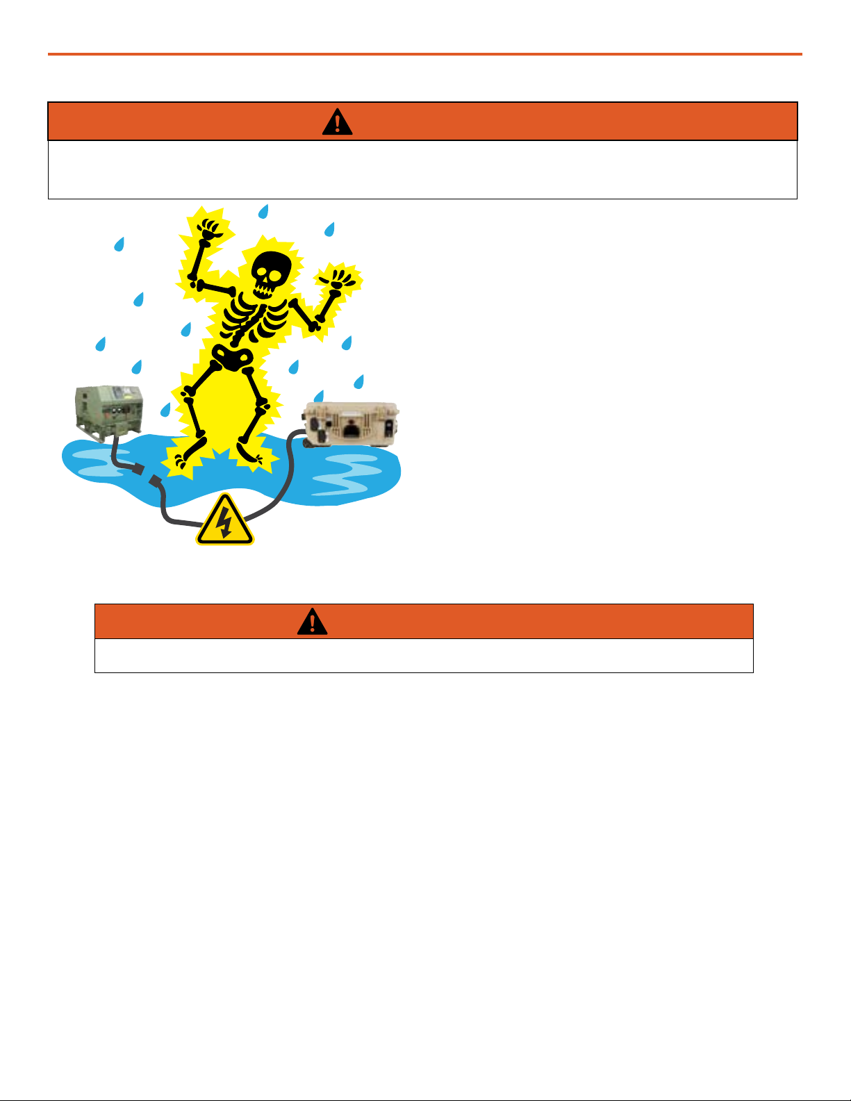
Electric Shock Hazard
WARNING
Standing water around the electrical equipment and/or intrusion of water into the System
components can increase the risk of electrical shock.
DON’T LET THIS BE YOU!
HIGH VOLTAGE: System components, PV
arrays, and generators may produce lethal
line voltages. Extreme care should be taken
to protect against electrocution. Always work
with another person in case an emergency
occurs. Disconnect power before performing
maintenance. Wear safety glasses whenever
working on any part of a system that requires
exposure to mechanical or direct electrical
contacts.
WARNING
The System is NOT GFCI protected.

November 2023 |Solar Stik®, Inc.16 |
24VDC HyPR 2500 Operator and Maintenance Manual
Environmental and Handling Precautions
All Solar Stik components are ruggedized, yet there are a few things the operator can do to prevent
failures and prolong the operational life of the Solar Stik System.
Water
If outdoor operation is necessary, the lids
of all components should be closed and
latched. During operation, cases should be
placed upright, especially during inclement
weather. Lids should be open only to access
operator controls and closed at all other
times.
Impact
Equipment should not be dropped onto hard
surfaces at a height greater than one foot
when transporting or during operation.
Dust/Foreign Object Intrusion
Air intake lters should be cleaned once per
month, or more frequently when conditions
warrant. As a general rule, minimize exposure
to high levels of particulates and foreign
object debris by exercising common-sense
placement and protection during both
operation and storage.
Heat
Heat and solar loading reduces efciency and
life expectancy. Shade components (except
PV panels) to prevent the negative effects of
heat.

|17November 2023 |Solar Stik®, Inc.
24VDC HyPR 2500 Operator and Maintenance Manual
The Inter-Connect System
A Solar Stik System is comprised of three (3) distinct types of technologies:
• Energy storage
• Power management
• Power generation
All of the individual components that operate in these categories utilize a unique connection
architecture known as the Inter-Connect Circuit.
The Inter-Connect Circuit is the connection framework of the System’s DC power network. It uses
a simple, polarized, locking connection that is common throughout the architecture. All power
management, energy storage, and power generation components are compatible with the Inter-
Connect Circuit.
Using a common, polarized connector allows rapid “Plug & Play” scaling of components, adaptation
of capabilities within the architecture, technology refreshment, and swapping of components when
conditions warrant. It also ensures that there is no unsafe way to make connections.
Circuit Breaker Protections
The Inter-Connect network is protected from overloads and short circuits through a network of circuit
breakers strategically placed throughout the circuit. It ensures the potential for a reverse polarity
connection within the circuit is minimized. If a problem occurs in a leg of the Inter-Connect Circuit,
the affected leg will disconnect from the primary network, leaving the other circuits functioning. If a
major failure occurs in the circuit, then the entire network will shut down for System and Operator
protection.
Operate with Voltage
The Inter-Connect Circuit communicates simple battery voltage to all components on the network,
allowing them to independently coordinate their respective functions. Battery voltage is used to
trigger actions such as power distribution timing, and more. Therefore, the proper setup of the Inter-
Connect Circuit is critical to properly communicate voltage to all points in the System and to ensure
all of the components operate together to provide seamless power to the load.
Optimize with Data
Data collection for a System occurs through the Inter-Connect network. Power management devices
such as HyPR 2500s and PRO-Verters meter voltage, current and time through the circuit, providing
critical real-time data the operator can use to troubleshoot and verify System performance. Data
collection enables programming/architectural changes to optimize performance based on evolving
conditions.

November 2023 |Solar Stik®, Inc.18 |
24VDC HyPR 2500 Operator and Maintenance Manual
Figure 4. Linear Inter-Connect Plug
• Polarized
• 200 A maximum current
• 24 VDC connection only
• Mechanically “locks” into place
• Rotate knob clockwise to lock,
counterclockwise to release
• Can be repaired or modied in the eld
Inter-Connect Cables for use with ESMs have two types of plugs: straight and angled. The straight
plug connects to the ESM to facilitate stacking (Figure 7).
24VDC Linear Inter-Connect Cable
Straight
Angled
Figure 5. Inter-Connect Plug
The Standard Inter-Connect Plug
• Polarized
• 200 A maximum current
• 24 VDC connection only
• Mechanically “locks” into place
• Rotate knob clockwise to lock,
counterclockwise to release
• Can be repaired or modied in the eld

|19November 2023 |Solar Stik®, Inc.
24VDC HyPR 2500 Operator and Maintenance Manual
EQUIPMENT DESCRIPTION
The HyPR 2500 manages power between power sources and loads. The HyPR 2500 provides both
AC and DC mechanisms to charge ESMs while the system is operating or idle. The HyPR 2500
provides important battery status information and therefore increased security for continuity of
operations.
The following diagram illustrates an overview or where to connect power sources, ESMs and loads
to the HyPR 2500.
Introduction
120 VAC Input
24VDC Input/Output x2
120VAC loads
24VDC HyPR 2500
Figure 6. 24 VDC HyPR 2500 connections

November 2023 |Solar Stik®, Inc.20 |
24VDC HyPR 2500 Operator and Maintenance Manual
30 A Max
AC Power Input Port
Figure 7. HyPR 2500 AC power input port
Connect AC power sources to the 120 INPUT port. The HyPR 2500 accepts 120 V power. Power via
this connection charges batteries and supports DC loads connected the 24VDC IN/OUT ports.
Grid
Connect generator power cables to the “AC INPUT” port on the left side of the HyPR.
Connecting Generators to HyPR
fuel-powered
generator 1-2 kW
120 VAC,
50 / 60 Hz
Figure 8. Connecting generators to HyPR
Other manuals for 24VDC HyPR 3000
2
Table of contents
Other Solar Stik Solar Panel manuals


Popular Solar Panel manuals by other brands

inventux
inventux X Series installation manual

GRIDFREE
GRIDFREE LIFESTYLE KIT installation manual

Hanwha Solar
Hanwha Solar HSL60P6-PB-1-xxx Series installation guide

PVP
PVP PVP-A Series General installation manual

Centrosolar
Centrosolar TFP 288 Professional installation guide

Sunport
Sunport SPP M60S Series Installation and user manual


Viessmann
Viessmann VITOSOL 200-F installation instructions

Link Energy
Link Energy Pilot Series installation guide

Silicon Solar
Silicon Solar MarineSol ThinFilm 12V30W user manual

Technaxx
Technaxx TX-271 user manual

Ubiquiti
Ubiquiti SUNMAX SP-260W user guide

Panasonic
Panasonic HIT VBHN330SA17 General installation manual