Ubiquiti SUNMAX SP-260W User manual

USER GUIDE


i
Table of Contents
Table of Contents
Chapter 1: Introduction....................................................... 1
Overview .................................................................................1
Safety.....................................................................................1
Recommendations....................................................................2
Points to Check Before Wiring .........................................................3
Wiring Solar Panels ...................................................................3
Wiring Solar Arrays to the Inverter .....................................................3
Measuring Output Voltage ............................................................3
Grounding ................................................................................3
Installation Requirements .................................................................4
Additional Tile Roof Mount Requirements .............................................4
Chapter 2: Components ...................................................... 5
Solar Panel................................................................................5
Panel Connector ..........................................................................5
Mounting Assembly.......................................................................6
Connector Mount .........................................................................6
Trim Cover Kit.............................................................................7
Jumper Cable .............................................................................7
Solar Gateway ............................................................................7
Roof Mount Kit............................................................................8
Tile Accessory Kit. . . . . . . . . . . . . . . . . . . . . . . . . . . . . . . . . . . . . . . . . . . . . . . . . . . . . . . . . . . . . . . . . . . . . . . . . .9
End Run ..................................................................................9
Y-Cables ................................................................................ 10
Portrait ............................................................................. 10
Landscape .......................................................................... 10
Cable Support Clips ..................................................................... 10
Chapter 3: Component Usage ...............................................11
Panel Connectors ....................................................................... 11
Mounting Assembly..................................................................... 12
Connector Mounts ...................................................................... 12
Trim Cover Kit........................................................................... 13
Landscape .......................................................................... 13
2-Panel Portrait ..................................................................... 13
1-Panel Portrait ..................................................................... 14
Cable Support Clips ..................................................................... 15
Flashing ................................................................................ 16
Jumper Cables .......................................................................... 16

ii
sunMAX™Solar User Guide
Y-Cables ................................................................................ 17
Example 1 .......................................................................... 18
Example 2 .......................................................................... 18
Example 3 .......................................................................... 19
Solar Panel.............................................................................. 20
Sample Layout Configurations ...................................................... 20
Chapter 4: Analysis ..........................................................23
Snow Loading .......................................................................... 23
Basic Wind Speed ....................................................................... 23
Roof Zones ............................................................................. 23
Exposure Category ...................................................................... 23
Grounding .............................................................................. 24
Special Mounting Considerations........................................................ 24
Maximum Cantilever .................................................................... 24
Chapter 5: AC Module Assembly .............................................25
Installing the Microinverter.............................................................. 25
QR Code Labels ..................................................................... 26
Installing the Cable Support Clips and Y-Cable ........................................... 27
Portrait Orientation ................................................................. 27
Landscape Orientation.............................................................. 28
Connecting Y-Cable to Microinverter .................................................... 29
Chapter 6: Installation .......................................................31
Roof Mount and Flashing Installation .................................................... 31
Mounting Assembly Installation ......................................................... 36
Leveling the Mounting Assemblies .................................................. 37
Trim Cover Installation .................................................................. 39
Trim Lock Installation ............................................................... 40
Panel Connector Installation for Trim Cover .............................................. 40
AC Module Installation .................................................................. 41
Solar Gateway .......................................................................... 44
Ports ............................................................................... 44
LEDs and Connectors ............................................................... 44
Installation ......................................................................... 45
Setup Using the Mobile App ........................................................ 46
Panels .............................................................................. 48
Solar Gateway ...................................................................... 51

iii
Table of Contents
End Run Installation..................................................................... 56
Safety .............................................................................. 56
Items Required ..................................................................... 56
Hardware Installation ............................................................... 56
Appendix A: Span Tables ....................................................61
Exposure Category B .................................................................... 61
Interior Zone........................................................................ 61
Edge Zone .......................................................................... 62
Exposure Category C .................................................................... 63
Interior Zone........................................................................ 63
Edge Zone .......................................................................... 64
Exposure Category D.................................................................... 65
Interior Zone........................................................................ 65
Edge Zone .......................................................................... 66
Appendix B: Tile Roof .......................................................67
Additional Tile Roof Mount Requirements ............................................... 67
Roof Mount and Flashing Installation .................................................... 67
Subflashing......................................................................... 67
Bibbing Method .................................................................... 71
Three-Course Method............................................................... 73
Upper Flashing ..................................................................... 75
Appendix C: Contact Information ............................................80

iv
sunMAX™Solar User Guide

1
Chapter 1: Introduction
Overview
sunMAX™by Ubiquiti Networks is a grid-tie solar solution that utilizes photovoltaic (PV) cells, or solar panels,
to convert solar energy into alternating current electricity. Using a watertight roof mounting system, sunMAX
offers both portrait and landscape array configurations with easy-to-use software to help you design and
implement a fully customizable solar solution.
The sunMAX solar solution should be deployed by an installer trained and familiar with the safety and
operational procedures of the sunMAX system and all of its components.
The solar panels are UL listed to standard 1703 and the mounting hardware is UL listed to standard 2703.
Please adhere to all applicable codes, required permits, and regulations concerning the installation and
inspection requirements as they pertain to your location.
Safety
The following instructions and safety precautions are in place to ensure proper deployment and
operation of your solar equipment:
• Use only the materials and tools specified in this guide.
• Do not break or modify any of the solar components or use them outside of their intended use.
• Do not sit or stand on the surface of the AC Modules.
• Install components securely to avoid parts from becoming loose or falling off during the
installation.
• Only work in dry conditions with dry tools.
• Prevent rafters and sheathing from becoming wet.
• Install each AC Module securely to ensure proper operation and grounding of the array.
• AC Modules are installed on rooftops where there is danger of slipping or falling. Ladders and
scaffolding should be used when climbing onto roofs.
• Do not use chemicals on solar modules when cleaning.
• Do not wear metallic jewelry or any conductive material.
• Do not touch electrical contacts, cables, or wires.
• Artificially concentrated sunlight shall not be directed onto the module or panel.

2
sunMAX™Solar User Guide
Recommendations
Note: Become familiar with the installation site and its surroundings by visiting the location prior to
the actual install date.
Take the following precautions before starting work:
• Plan the job and visit the site before doing any work.
• Always work with at least one other person on site.
• Inspect power tools before using them.
When conditions make it necessary, tell workers to stop working.
• Do not perform installation in poor weather conditions such as rain, snow, ice, or high winds.
Wear appropriate work clothes and protective equipment.
• Wear gloves when handling sunMAX components. Flashing has sharp edges and will get hot when
exposed to sunlight.
• Work clothes for both the upper and lower body should fit well and allow you to move freely.
• Always wear protective equipment such as harnesses and lifelines.
• Wear non-slip shoes. Shoes get dirty when worn on a roof, so keep the soles clean.
Observe safety regulations for ascending and descending ladders and stepladders.
• Ladders from a first-story roof to a second-story roof are very dangerous. Do not set up a ladder on
a roof.
• When there is no other choice, straddle the ridge and lay down a rubber anchor mat, and secure
the ladder to the mat. Always have one person hold the ladder firmly.
• When you use a two-stage ladder, secure it with ropes or stays to prevent it from sliding sideways,
and have two people hold the ladder steady.
• Use ladders with steps broad enough to permit safe work.
When working in high places, wear harnesses and use scaffolding.
• When working at heights of 6' (1.83 m) or more, use scaffolds or other equipment to ensure a
stable work platform.
• Scaffolds should be designed and erected by a qualified person.
• When it is difficult to erect a stable work platform, install safety nets, wear harnesses, and take
other measures to prevent falls.
• Regulations mandate the use of harnesses. Fasten harnesses securely, and check that the length of
lifelines is 6' (1.83 m) or less.
• Attach the support line securely to a metal fixture installed for that purpose on a ridge or beam.
Install enclosures and covers to minimize risks.
• Install enclosures, guardrails, or covers at the end of work decks that are 10' (3.05 m) or more above
ground, at openings, and at other dangerous locations.
• When it is extremely difficult to install enclosures, guardrails, or covers, or when they must be
removed to work in that location, install a safety net, wear harnesses, and take other measures to
prevent falls.

3
Chapter 1: Introduction
WARNING: Wiring work should be performed according to the provisions of the National Electrical
Code. Grounding work and wiring connections to the inverter should be performed by a qualified
electrician.
Please adhere to all applicable codes, required permits, and regulations concerning the installation and
inspection requirements as they pertain to your location. Pay special attention to Article 110, Chapter 2
Article 250, Chapter 3, Articles 300, 310, 480, and 690.
WARNING: The solar array generates electricity whenever it is exposed to sunlight. Be careful when
handling it. There is a danger of shock if you touch the connectors or wires of the electric cables.
Points to Check Before Wiring
• The solar modules generate electricity when exposed to light. You will need to wear insulating gloves.
• You will need a multimeter for volts, amps, resistance, and continuity capable of measuring DC and AC
up to 600V and 40A.
• Make sure your tools are insulated.
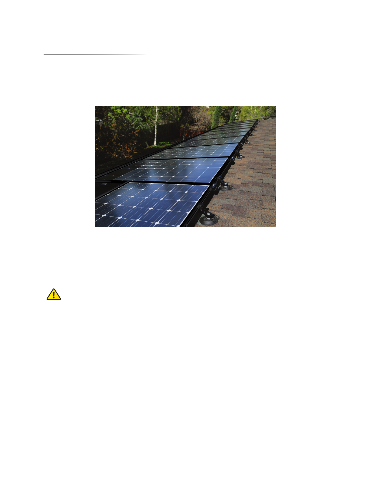
Wiring Solar Panels
• Never step or sit on the glass surface of the solar modules. The glass may break.
• When you install the solar modules on the mount, never allow an output cable to become caught
between the mount and a module frame.
• Ensure that the module connectors are fully inserted. There is a risk of malfunction if they are not
pushed all the way in.
• Support output cables to eliminate slack. High winds can blow slack cable against the mount, damaging
the cables.
Wiring Solar Arrays to the Inverter
• For wiring through walls, protect the cables with metal conduits, flexible metal conduits as permitted or
required by local and national electrical or building codes. Failure to do so can result in shock and short
circuits. Always use conduit to protect sections of array output cables that are exposed to sunlight.
• For wiring outdoors, protect cables with PVC conduits, metal conduits, or flexible conduits.
• Prevent water from entering or building up in conduit by using waterproof fittings or duct seal.
• To prevent shock, tape and label the cut ends of array output extension cables (the side opposite to
the connector side) before connecting to solar module output cables. Then, tape them again after
measuring the voltage of each array.
• To prevent shock when you connect the array output cables to the inverter, remove the tape one cable
at a time as you connect the cables.
Measuring Output Voltage
• Ensure that all solar modules are exposed to sunlight. (Remove lightproof sheets, if present.)
• Set the voltmeter measurement range to a DC voltage greater than -32VDC.
• Keep the plus (+) solar array output cables away from the ends of the minus (-) cables, as dangerous arcs
can occur. The array output voltage under normal conditions (clear skies) can be very high.
Grounding
• Use a proper ground wire according to your local safety regulations and requirements. For more
information, refer to “Grounding” on page 24 in this User Guide.
• Follow NEC 690 grounding provisions.

4
sunMAX™Solar User Guide
• Each sunMAX module is considered to be in compliance with UL 1703 only when the module is
mounted in the manner specified by these instructions.
• A sunMAX module with exposed conductive parts is considered to be in compliance with UL 1703
only when it is electrically grounded in accordance with the instructions presented below and the
requirements of the National Electrical Code.
• Any module without a frame (laminate) shall not be considered to comply with the requirements of UL
1703 unless the module is mounted with hardware that has been tested and evaluated with the module
under this standard or by a field Inspection certifying that the installed module complies with the
requirements of UL 1703.
• Routine maintenance or servicing of a SunMAX module shall not involve breaking or disturbing the
bonding path.
• Grounding connections should only be installed by qualified personnel.
• Only use approved SunMAX hardware to maintain the UL1703, UL2703, UL467 ratings of the installed
system in the approved manners described in this manual.
Installation Requirements
• No. 2 Phillips screwdriver
• Leveling string
• Tape measure
• Electric drill
• 3/16"(4.8 mm) long drill bit
• Chalk line
• Chalk stick (for cutting shingle)
• Tin snips or utility knife (for cutting shingle)
• 13 mm wrench (preferably an impact driver)
• Caulking gun
• EPDM-compatible roof caulking
• Shingle ripper or other prybar to remove existing nails
Additional Tile Roof Mount Requirements
• Angle grinder/saw with a masonry blade
• Roofing paper and roofing cement
• Felt paper

5
Chapter 2: Components
Solar Panel
The Solar Panel, model SM-SP-260W-DC-EU, can be installed in portrait orientation, landscape orientation,
or a combination of both. Prior to transferring the Solar Panels to the roof for installation, each will be
assembled with cabling and a Microinverter. The assembled parts will be referred to as an ACModule. Each
panel in the array is installed downroof in the lower-edge position, side by side until a row is complete.
64.92” (1649 mm)
39.06”(992 mm)
Topside View of Solar Panel
(Portrait Orientation)
Underside View of Solar Panel
(Portrait Orientation)
(Landscape Orientation)
Panel Connector
Panel Connectors, model SM-PC, join solar panels together structurally between adjacent corners and along
the outside edges of the Solar Panels and bond them together electrically. The arrow located on the top
surface of each Panel Connector should always point downward towards the Trim Cover.

6
sunMAX™Solar User Guide
Mounting Assembly
Mounting Assemblies, model SM-MA, provide structural support and 360° adjustment swivel between the
Roof Mount and outer edges of the Solar Panel. The arrow located on the top surface of each Mounting
Assembly should always point downward towards the Trim Cover.
Connector Mount
Connector Mounts, model SM-CM, provide structural support and 360° adjustment between the Roof Mount
and outer edges of the Solar Panel where Mount Assemblies would coincide with a Panel Connector location.
Each Connector Mount has an arrow on the top surface of the 360° swivel that should always face forward
toward the Trim Cover.

7
Chapter 2: Components
Trim Cover Kit
The Trim Cover Kit is used to enhance the visual appearance and aesthetics along the entire front edge of the
array and help ease installation of the panels. There are three versions of the Trim Cover Kit: 1-panel portrait
(SM-TC-1P), 2-panel portrait (SM-TC-2P), and landscape (SM-TC-L).
Jumper Cable
Jumper Cables, model SM-JC-4C, connect and extend the Y-Cables in adjacent rows together underneath the
solar array. Jumper Cables attach to the inside edge of the Solar Panels using Cable Support Clips.
Solar Gateway
The Solar Gateway, model SM-SG, communicates with and gathers data from all Microinverters in the solar
array and sends information to the Ubiquiti®sunMAX cloud management system via the local area network.

8
sunMAX™Solar User Guide
Roof Mount Kit
The Roof Mount Kit, model SM-RM-C, provides a structural mount between the roof surface and Mounting
Assembly to support the array. The kit includes the roof mount and mounting hardware, roof flashing, and
counter flashing to ensure a watertight installation.
Note: The Flashing has sharp edges and will get hot when exposed to sunlight.

9
Chapter 2: Components
Tile Accessory Kit
Used in conjunction with the Roof Mount Kit, the Tile Accessory Kit, model SM-RM-T, includes additional
components required for tile-roof mounting: a threaded stud, extension post, upper aluminum Flashing, and
counter flashing. The upper aluminum Flashing is flexible and can be formed to fit most flat or curved tiles.
Note: The Flashing has sharp edges and will get hot when exposed to sunlight.
End Run Connector Kit
The End Run Connector, model SM-EC-EU, provides easy adaptation of cabling from the array to the electrical
panel feeding the grid. It connects the open-ended Y-cable in your solar array to the house-side wiring that
feeds into the electrical panel of your building. The End Run is part of a kit and includes the End Run, a cabling
end cap, and grounding stud with nut.
Note: Install the Solar Panels so that the End Run will terminate near the breaker box or closest to
the location where the house-side wiring will penetrate the roof.

10
sunMAX™Solar User Guide
Y-Cables
Portrait
The Portrait Y-Cables, model SM-YC-P4, are used to connect panels and devices, such as the Solar Gateway or
Microinverter, in a portrait-array configuration.
Landscape
The Landscape Y-Cables, model SM-YC-L4, are used to connect panels and devices, such as the Solar Gateway
or a Microinverter, in a landscape-array configuration.
Cable Support Clips
The Cable Support Clips, model SM-CC, slide onto the inner frame underneath the Solar Panel and pivot down
over the outer edge of the frame. Cable Support Clips support Jumper Cables and Y-Cables along the inside
edges of the Solar Panels.

11
Chapter 3: Component Usage
All sunMAX mounting components are installed into frame of the Solar Panel using the same motion.
Components hook underneath the outer edge of the panel’s frame and then pivot down. Never force a
component into place as it can damage the frame of the Solar Panel.
Panel Connectors
Panel Connectors, model SM-PC, join Solar Panels together structurally between adjacent corners and
along the outside edges of the Solar Panels and bond them together electrically. The arrow located on the
top surface of each Panel Connector should always point downward towards the Trim Cover. Do not install
vertically between the panels in your array.
If a Mounting Assembly is near a Panel Connector location, install the Panel Connector first, then install the
Mounting Assembly.

12
sunMAX™Solar User Guide
Panel Connectors have preset gaps on them where the Solar Panels will fit in as they come together during
the installation. Align the preset gaps with the edge of the Solar Panel before hooking the Panel Connector
underneath the frame and pivoting down.
Mounting Assembly
Mounting Assemblies provide structural support and 360˚ adjustment between the Roof Mount and the outer
edges of the Solar Panel. The Mounting Assembly base also slides forward and backward to allow adjustment
of the swivel mount position. The arrow located on the top surface of each Mounting Assembly should always
point downward towards the Trim Cover.
Connector Mounts
The same function and installation rules apply to the Connector Mounts as well. Connector Mounts, model
SM‑CM, provide structural support and 360˚ adjustment between the Roof Mount and outer edges of the
array where Mounting Assemblies would coincide with a Panel Connector location.

13
Chapter 3: Component Usage
Trim Cover Kit
The Trim Cover Kit serves as an assembly aid for alignment and maintains the Class A fire rating when
installed. There should always be at least one Mounting Assembly and one Panel Connector per Trim Cover.
There are three different Trim Covers available for use depending on the design and orientation of your array:
Landscape, 2-Panel Portrait, and 1-Panel Portrait.
Landscape
In landscape layout, there will be one landscape Trim Cover per column. The standard width of one landscape
Trim Cover is the same width as one Solar Panel in landscape orientation.
2-Panel Portrait
The 2-Panel Portait Trim Cover is the standard width of two Solar Panels in portrait orientation. For every two
columns of Solar Panels in portrait layout, there will be one Trim Cover that extends along the front row of
both panels. For example, in an eight-column array of portrait Solar Panels, use four of the SM-TC-2P Trim
Covers.

14
sunMAX™Solar User Guide
1-Panel Portrait
The 1-Panel Portrait Trim Cover is used in a solar array where there are an odd number of portrait columns.
For example, in an array of three portrait columns, use one 2-Panel Portrait Trim Cover and one 1-Panel
Portrait Trim Cover. The 1-Panel Portait Trim Cover is the standard width of a single Solar Panel in portrait
orientation.
The Trim Covers also come with two end plates. Most solar arrays use multiple Trim Covers side by side across
the front edge of the array. Once the front edge of your solar array is complete, install an end plate on both
ends of the Trim Cover using the included mounting screws.
This manual suits for next models
2
Table of contents
Other Ubiquiti Solar Panel manuals
Popular Solar Panel manuals by other brands

CORAB
CORAB PB-066 installation manual

Qcells
Qcells Q.PEAK DUO XL-G10.c Installation and operation manual

CORAB
CORAB B-027 installation manual

Sun Power
Sun Power SPR-E-Flex-110 Safety and installation instructions

CORAB
CORAB T-023 installation manual

Qcells
Qcells Q.PEAK DUO-G7 Series Installation and operation manual

SCHOTT solar
SCHOTT solar ASE-300-DGF/50 Installation, operation and maintenance manual

Falcon
Falcon SP100DV2 quick start guide

2M Technology
2M Technology VSC-3000A operating manual

Heliene
Heliene HEE210U Series Operation/maintenance and installation

Snapper
Snapper 1690226 Operator's manual

Nature Power
Nature Power 50042 installation manual