Solar Stik 19-1000012 User manual

OPERATION AND MAINTENANCE MANUAL
FOR THE
SOLAR VENTURE 320 W ARRAY
P/N 19-1000012
Updated: 20231129
DISTRIBUTION STATEMENT A. Approved for public release; distribution is unlimited.

Operation and Maintenance Manual for the Solar Venture 320 W Array
2 |
List of Figures
Figure 1. Solar Array safety labels.................................................................................................................................... 4
Figure 2. Deploying Array Stand....................................................................................................................................... 6
Figure 3. 30º Mesh Hold Down installation ...................................................................................................................... 7
Figure 4. 60º Mesh Hold Down installation ...................................................................................................................... 8
Figure 5. Ground-securing Mesh conguration for 30º and 60º Array deployment ......................................................... 9
Figure 6. Connecting Array to Array Stand....................................................................................................................... 9
Figure 7. Locking the Array into place on the Array stand ............................................................................................... 9
Figure 8. Sandbag placement for 30º and 60º Array deployment.................................................................................. 10
Figure 9. Conguring ground-securing Mesh for at (0º) deployment ........................................................................... 11
Figure 10. Sandbags placement for 0º deployment....................................................................................................... 11
Figure 11. Connecting Array to Solar Cable................................................................................................................... 12
Figure 12. Packing Solar Venture 320 W Array............................................................................................................... 14
Figure 13. Measuring Solar Panel and Array open circuit voltage Voc ........................................................................... 16
Contents
GENERAL INFORMATION, THEORY OF OPERATION, AND EQUIPMENT DESCRIPTION 3
Product Safety Information and Instructions . . . . . . . . . . . . . . . . . . . . . . . . . . . . . . . . . . . 3
Safety Information Labels . . . . . . . . . . . . . . . . . . . . . . . . . . . . . . . . . . . . . . . . . . . . . 4
Electric Shock Hazard Related to Solar Panels . . . . . . . . . . . . . . . . . . . . . . . . . . . . . . . . . .4
Equipment Description . . . . . . . . . . . . . . . . . . . . . . . . . . . . . . . . . . . . . . . . . . . . . . . 5
Solar Array Kit Contents. . . . . . . . . . . . . . . . . . . . . . . . . . . . . . . . . . . . . . . . . . . . . .5
OPERATOR INSTRUCTIONS . . . . . . . . . . . . . . . . . . . . . . . . . . . . . . . . . . . 5
Solar Array Setup . . . . . . . . . . . . . . . . . . . . . . . . . . . . . . . . . . . . . . . . . . . . . . . . . . 5
1. Unpack and Inventory Solar Array Components . . . . . . . . . . . . . . . . . . . . . . . . . . . . . . . . 5
2. Extend and Lock Array Stand . . . . . . . . . . . . . . . . . . . . . . . . . . . . . . . . . . . . . . . . . 6
3. Install 30º Mesh Hold Down . . . . . . . . . . . . . . . . . . . . . . . . . . . . . . . . . . . . . . . . . . 7
4. Install 60º Mesh Hold Down . . . . . . . . . . . . . . . . . . . . . . . . . . . . . . . . . . . . . . . . . . 8
5. Mesh Conguration for 30º and 60º Deployments . . . . . . . . . . . . . . . . . . . . . . . . . . . . . . . 9
6. Install Panel onto Array Stand . . . . . . . . . . . . . . . . . . . . . . . . . . . . . . . . . . . . . . . . . 9
7. Secure Array to Ground. . . . . . . . . . . . . . . . . . . . . . . . . . . . . . . . . . . . . . . . . . . . 10
a. Ground-securing for 30º and 60º Deployments . . . . . . . . . . . . . . . . . . . . . . . . . . . . . 10
b. Mesh Conguration and Ground-securing for Flat (0º) Deployments . . . . . . . . . . . . . . . . . . 11
8. Connect Solar Cable to Solar Array Leads . . . . . . . . . . . . . . . . . . . . . . . . . . . . . . . . . . 12
9. Connect Array(s) to Power Hub. . . . . . . . . . . . . . . . . . . . . . . . . . . . . . . . . . . . . . . . 12
10. Position Array for Optimal Power Generation . . . . . . . . . . . . . . . . . . . . . . . . . . . . . . . . 13
Derating, Solar Loading, and Airflow. . . . . . . . . . . . . . . . . . . . . . . . . . . . . . . . . . . . . . . 13
Disconnecting Array . . . . . . . . . . . . . . . . . . . . . . . . . . . . . . . . . . . . . . . . . . . . . . . . 13
Stowing Array . . . . . . . . . . . . . . . . . . . . . . . . . . . . . . . . . . . . . . . . . . . . . . . . . . . 14
MAINTENANCE . . . . . . . . . . . . . . . . . . . . . . . . . . . . . . . . . . . . . . . . . .15
TROUBLESHOOTING . . . . . . . . . . . . . . . . . . . . . . . . . . . . . . . . . . . . . . .15
Measuring Array Voltages: Background . . . . . . . . . . . . . . . . . . . . . . . . . . . . . . . . . . . . . 15
Procedure to Measure Array and Panel Voc with a Multimeter. . . . . . . . . . . . . . . . . . . . . . . . . . 16
Array and Panel Short Circuit Current.. . . . . . . . . . . . . . . . . . . . . . . . . . . . . . . . . . . . . . 16
TECHNICAL SPECIFICATIONS . . . . . . . . . . . . . . . . . . . . . . . . . . . . . . . . . .17

| 3
Operation and Maintenance Manual for the Solar Venture 320 W Array
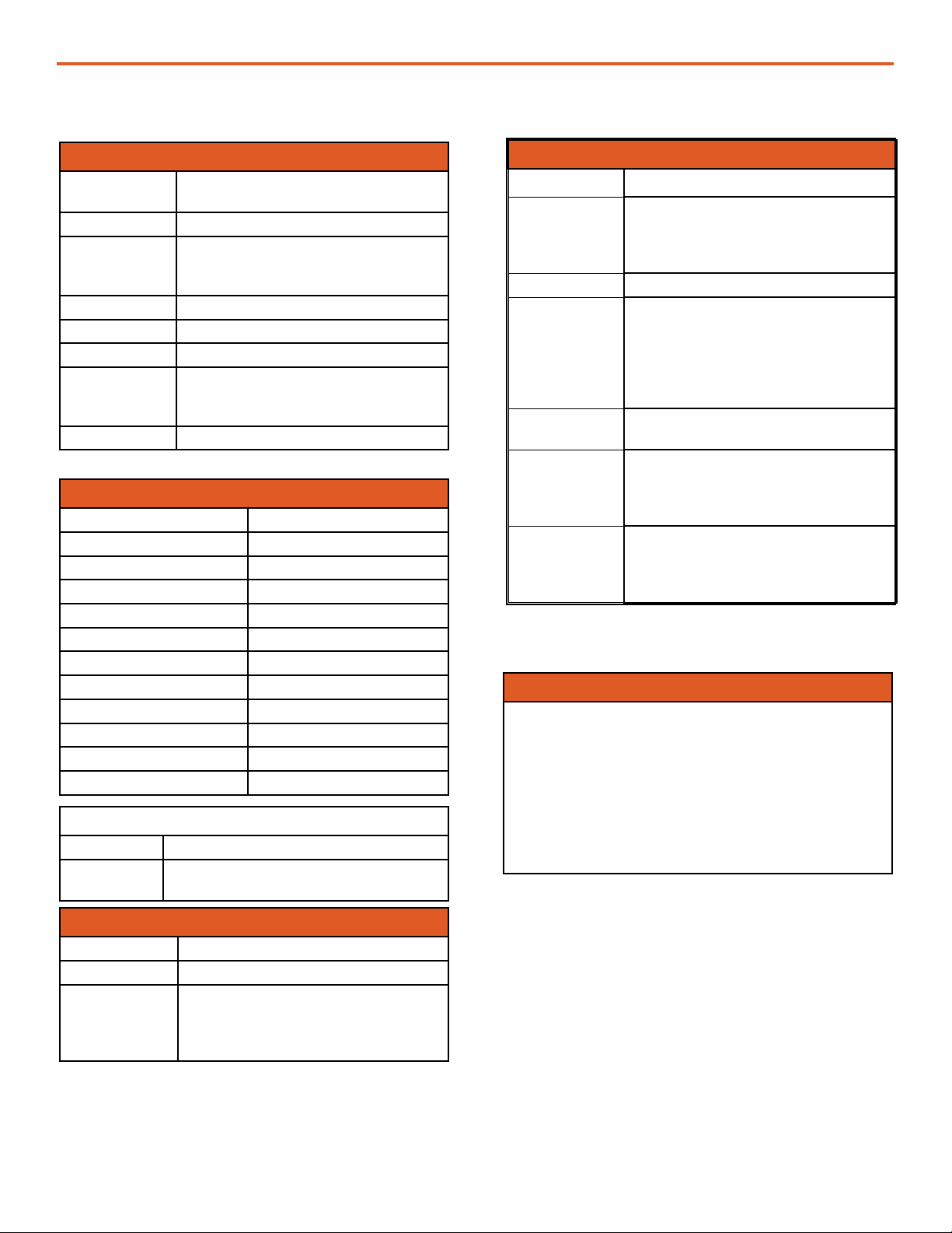
Section Page(s) Description Date
Initial Release June 2021
Stowing 24 Illustration and use of Hard Case April 2022
All all Reduce content to 10 double sided pages. April 2022
All All Overall editing May 2023
All All Overall editing Aug 2023
Revision History
List of Tables
Table 1. Solar Venture 320 W Array Kit (P/N 19-1000012) contents ............................................................................... 5
Table 2. Ground Securing Kit (12-1000009) contents ...................................................................................................... 5
The Solar Venture 320 W is designed to generate renewable power in expeditionary applications
where weight, rugged design, and extreme portability are factors.
The Array can be deployed on any terrain, and can generate up to 320 watts of power for
applications where independence from traditional power sources is required. The 320 W Array is
modular and scalable, allowing users to tailor power generation capability to load requirements.
The mono-crystalline cells in the high efciency Solar Panels are laminated onto a carbon-ber
structure, which combines extremely high PV performance with incredibly light material for an
extraordinary watt-to-weight ratio. The Array offers a superior integration of technologies to provide
the operator with highest power in the smallest renewable generator footprint.
GENERAL INFORMATION, THEORY OF OPERATION, AND
EQUIPMENT DESCRIPTION
Product Safety Information and Instructions
This manual contains important safety instructions that must be followed during the installation and
operation of the Solar Array. Read all instructions and safety information contained in this manual.
Operation and Maintenance Manual for the Solar Venture 320 W Array
4 |
Your safety and the safety of others is very important. This manual provides guidance on safe
operating practices and how to achieve maximum performance from the MEHPS-Solar Array. Always
observe and follow all safety protocols outlined below:
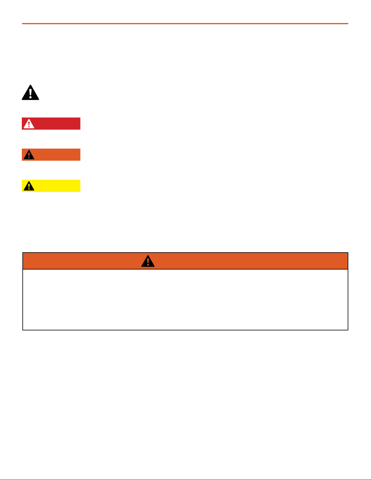
This is the safety alert symbol. This symbol alerts you to potential hazards that can kill you or
hurt you and others. All safety messages will follow the safety alert symbol and the word
“DANGER”, “WARNING”, or “CAUTION”. These words are dened as:
DANGER Indicates a hazardous situation which, if not avoided, will result in death or
serious injury.
WARNING Indicates a hazardous situation which, if not avoided, could result in death or
serious injury.
CAUTION Indicates a hazardous situation which, if not avoided, could result in minor or
moderate injury.
All safety messages will identify what the potential hazard is, how to reduce the chance of injury, and
what can happen if the instructions are not followed.
Safety Information Labels
Electric Shock Hazard Related to Solar Panels
WARNING
• Solar Panels produce electricity when exposed to sunlight.
• Live power may be present at multiple terminals.
• Never route the cables through standing water.
• All cables and connections should remain dry and should be inspected regularly to ensure safe
operating conditions.
• Do not disconnect Solar Cables when under load.
• Eliminate Panel exposure to sunlight before disconnecting Solar Cables to prevent arcing.
Connecting and disconnecting Solar Cables may result in arc ash when the cables are under load
(carrying current) from an active Solar Panel or Array.
Warnings to this effect are present at multiple locations on Solar Cables, connectors and the Solar
Panel itself (Figure 1 ).
Figure 1. Solar Array safety labels
| 5
Operation and Maintenance Manual for the Solar Venture 320 W Array
Equipment Description
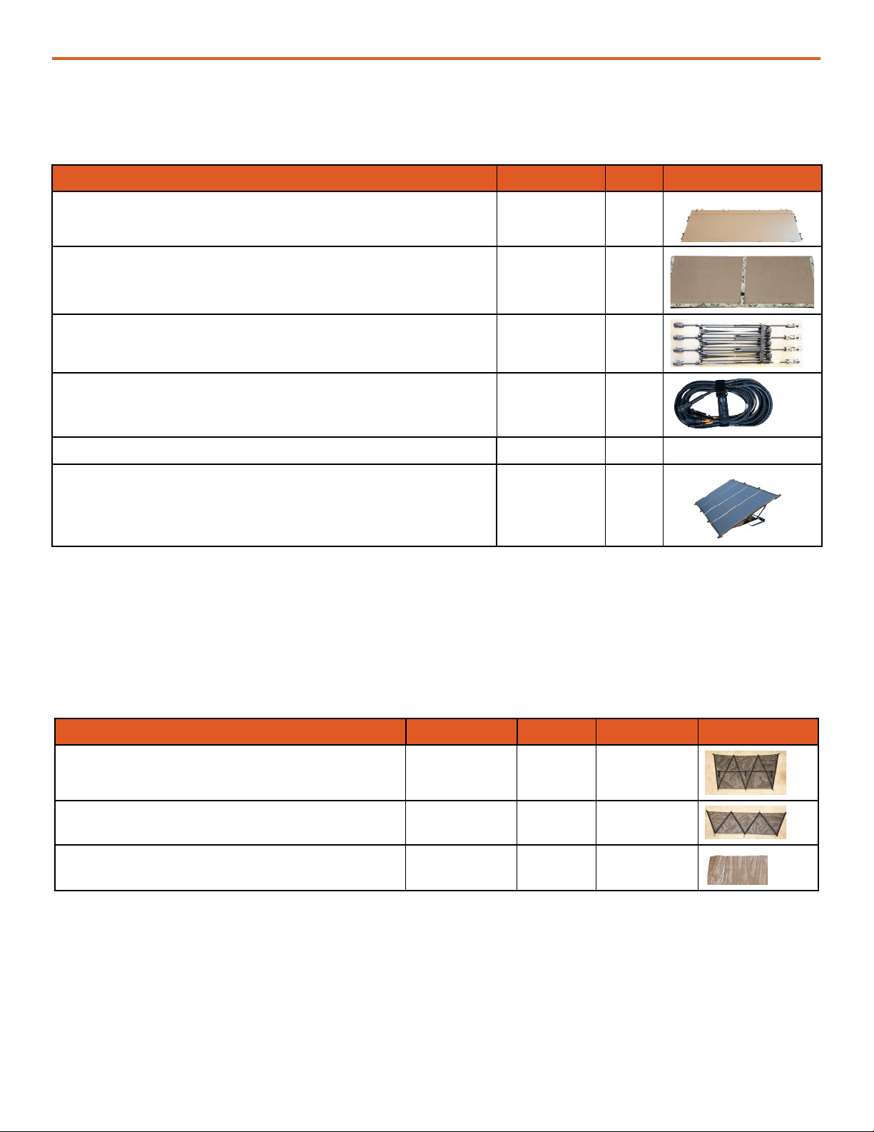
Components of MEHPS-Solar Array P/N Qty Image
Hard Case, Solar Venture 320W 14-1000035 1
Panel, Solar Venture 320W 14-1000037 1
Stand, Solar Venture 14-1000033 2
Cable, Solar Venture 13-1000350 1
Ground Securing Kit 12-1000009 2 See Table 2
Operation and Maintenance Manual 19-1000012 1
Table 1. Solar Venture 320 W Array Kit (P/N 19-1000012) contents
Solar Array Kit Contents
Components of Ground Securing Kit P/N Qty / Kit Qty / Array Image
Mesh Hold Down, 30 Deg 08-1000086 1 1
Mesh Hold Down, 60 Deg 08-1000087 1 1
Sandbags 12-1000007 7 7
Table 2. Ground Securing Kit (12-1000009) contents
1. Unpack and Inventory Solar Array Components
Solar Array Setup
OPERATOR INSTRUCTIONS
Remove Solar Array components from Soft Case. Inventory Components shown in Table 1 and
Table 2. Two (2) Ground Securing Kits are packed together in Soft Case small compartment.
Operation and Maintenance Manual for the Solar Venture 320 W Array
6 |
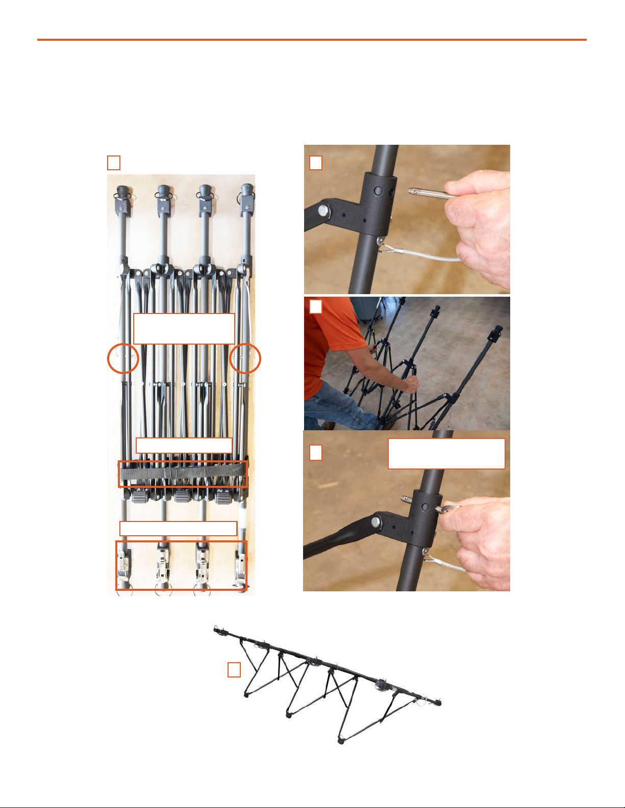
2. Extend and Lock Array Stand
Locking pins-
storage position
Transport strap
A B
C
D
E
Disconnect the velcro transport strap securing the foldable Array Stand (Figure 2A). Remove the
two (2) locking pins (Figure 2B) to allow the Array Stand to expand. Expand the Array Stand (Figure
2C) and install the locking pins in the “deployed” position (Figure 2D) after the Array Stand is fully
extended (Figure 2E).
Tensioning clamps
Locking pins -
deployed position
Figure 2. Deploying Array Stand
| 7
Operation and Maintenance Manual for the Solar Venture 320 W Array
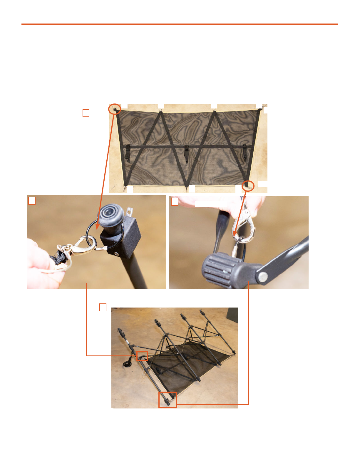
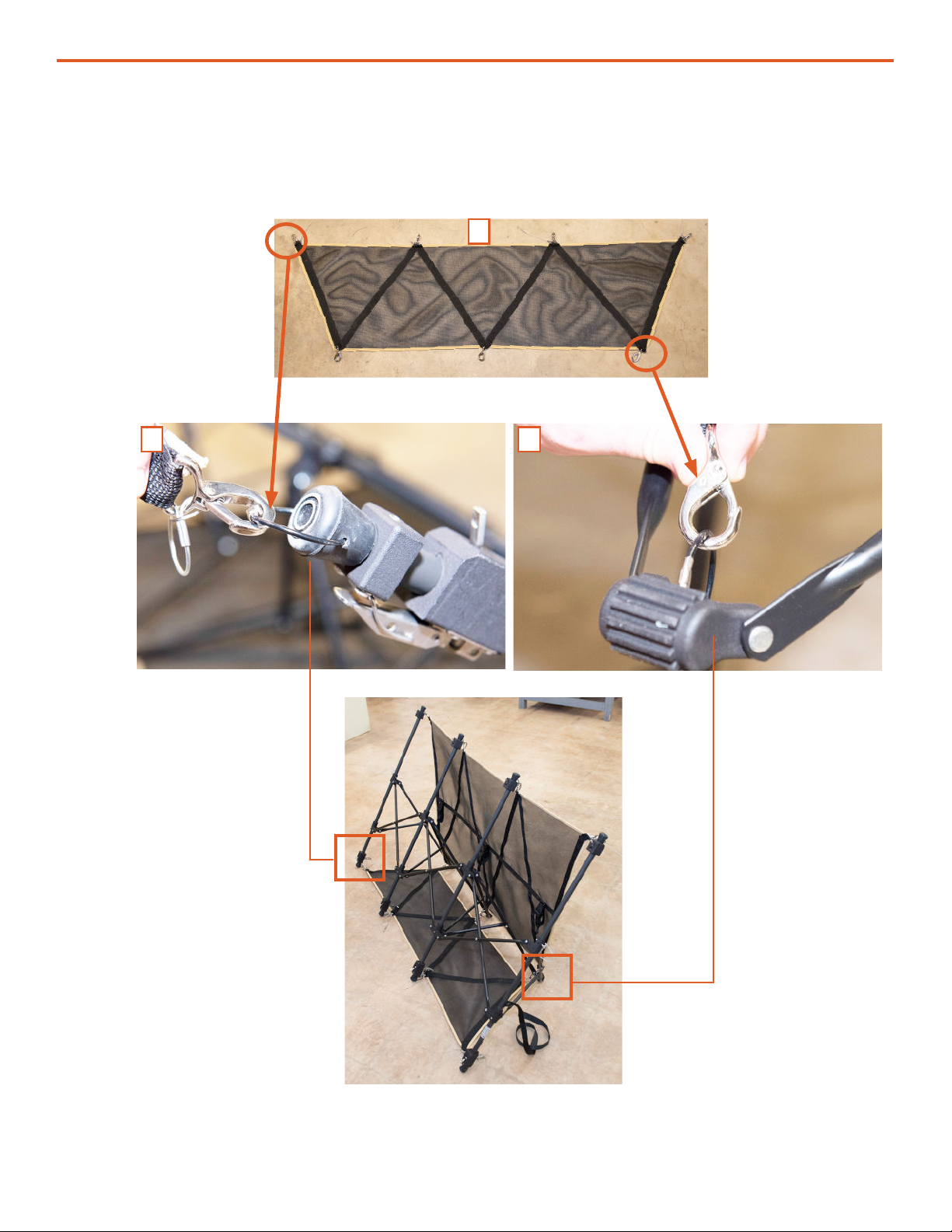
3. Install 30º Mesh Hold Down
The 30º Mesh hold down attachment has three (3) clips on the short side and four (4) on the long
side (Figure 3A). The clips on the short side connect to the rings on the three (3) cleats (Figure 3B)
of the Array Stand. Connect the four (4) clips on the long side of Mesh to the wire loops (Figure 3C)
at the low end of the support frame bar (Figure 3D). The Mesh will be stretched tight when all of the
connections are made.
A
1
1
2
2
3
3
4
BC
D
Wire loop
Figure 3. 30º Mesh Hold Down installation
Long Side
Short Side
Operation and Maintenance Manual for the Solar Venture 320 W Array
8 |
4. Install 60º Mesh Hold Down
The 60º Mesh Hold Down has three (3) clips on the short side and four (4) on the long side (Figure
4A). The clips on the long side connect to the wire rings (Figure 4B) on the round feet associated
with the tensioning latch. The three (3) clips on the short side connect to the three (3) support frame
cleats (Figure 4C).
Figure 4. 60º Mesh Hold Down installation
A
B C
| 9
Operation and Maintenance Manual for the Solar Venture 320 W Array
Figure 5. Ground-securing Mesh conguration for 30º and 60º Array deployment
5. Mesh Configuration for 30º and 60º Deployments
Connect the large and small Meshes as shown in Figure 5 to deploy the Array at 30º (A) or at 60º (B).
A
6. Install Panel onto Array Stand
Each Panel has eight (8) grommet-reinforced holes, four (4) on the top and four (4) on the bottom
(Figure 6A, orange circles). The Array Stand has eight (8) complementary Panel mounting hooks
(Figure 6B). The latching mechanism on this side of the frame is xed. Connect the Panel to this row
of xed mounting hooks rst (Figure 6B). Mount Panels onto Array Stands in the same orientation.
B
The hooks on other side of the Panel are part of a sliding tensioning clamp. Figure 7A shows the
Array Stand in the storage conguration with tensioning clamps in locked and unlocked positions.
Unlock the clamp lever to allow the hook to slide (Figure 7B). Place the hook into the hole, then
tighten (Figure 7C) and lock the clamp (Figure 7D). Repeat for each of the four (4) mounting holes
until the Array is secured to the support frame.
Figure 6. Connecting Array to Array Stand
Figure 7. Locking the Array into place on the Array stand
Array backside
Power output
leads
A B C D
Unlock and Slide
Unlocked
Locked Hook Lock
A
BA

Operation and Maintenance Manual for the Solar Venture 320 W Array
10 |
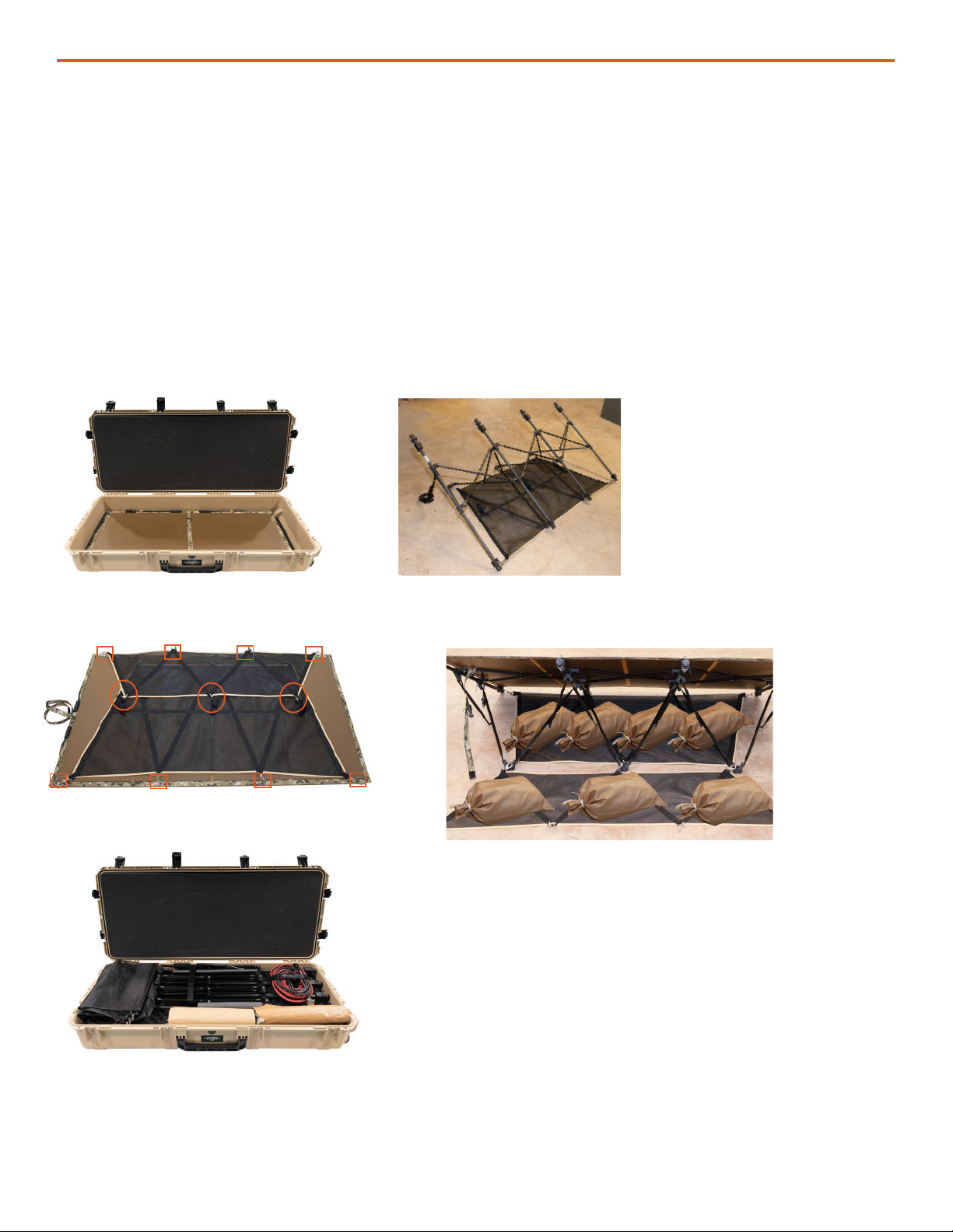
The Array must be secured with sandbags (Figure 8) to reduce the potential for displacement or
damage in high winds. Each 320 W Array kit provides 7 sandbags. Wind-testing data indicate that
the Array will withstand displacement in winds of 60 mph (97 kph) when weighted with seven (7)
sandbags for the entire Array. Use the best available information when determining how many
sandbags to use.
Sandbags should weigh a minimum of 50 pounds (23 kg) each. Place sandbags on the ground-
securing Mesh under the Panel and on the Mesh behind the Panel as shown below (Figure 8).
7. Secure Array to Ground
WARNING
Failure to properly secure Array(s) to ground with sandbags could result in Array damage,
personnel injury, or death in high winds. Wind damage can render Array nonfunctional or
signicantly reduce their functional life expectancy. Array must be properly secured to the
ground even in low-wind environments.
CAUTION
DO NOT DAMAGE THE ARRAY SUPPORT FRAME.
DO NOT DROP SANDBAGS ONTO THE ARRAY SUPPORT FRAME.
Do not secure the Array to the ground before establishing proper location and orientation.
Before the Array are secured to the ground, be observant and take care to ensure the support frame
is not twisted. If the support frame is twisted, the Array will be exposed to torsional strain, which can
cause damage to the cells.
a. Ground-securing for 30º and 60º Deployments
Congure the Mesh for the desired angle of deployment (Figure 4 & Figure 5). Ensure the Array
is oriented for maximum energy harvesting and that the Solar Cable will reach the Power Hub.
Generally speaking, the lower angle (30º) will harvest energy more efciently in the summer when the
sun is overhead. During the winter, the steep angle (60º) will be more efcient.
Place seven (7), 50-lb (23 kg) sandbags on the Mesh as shown below. Sandbags are illustrations
and not to scale.
30º - Best for summer 60º - Best for winter
Figure 8. Sandbag placement for 30º and 60º Array deployment

| 11
Operation and Maintenance Manual for the Solar Venture 320 W Array
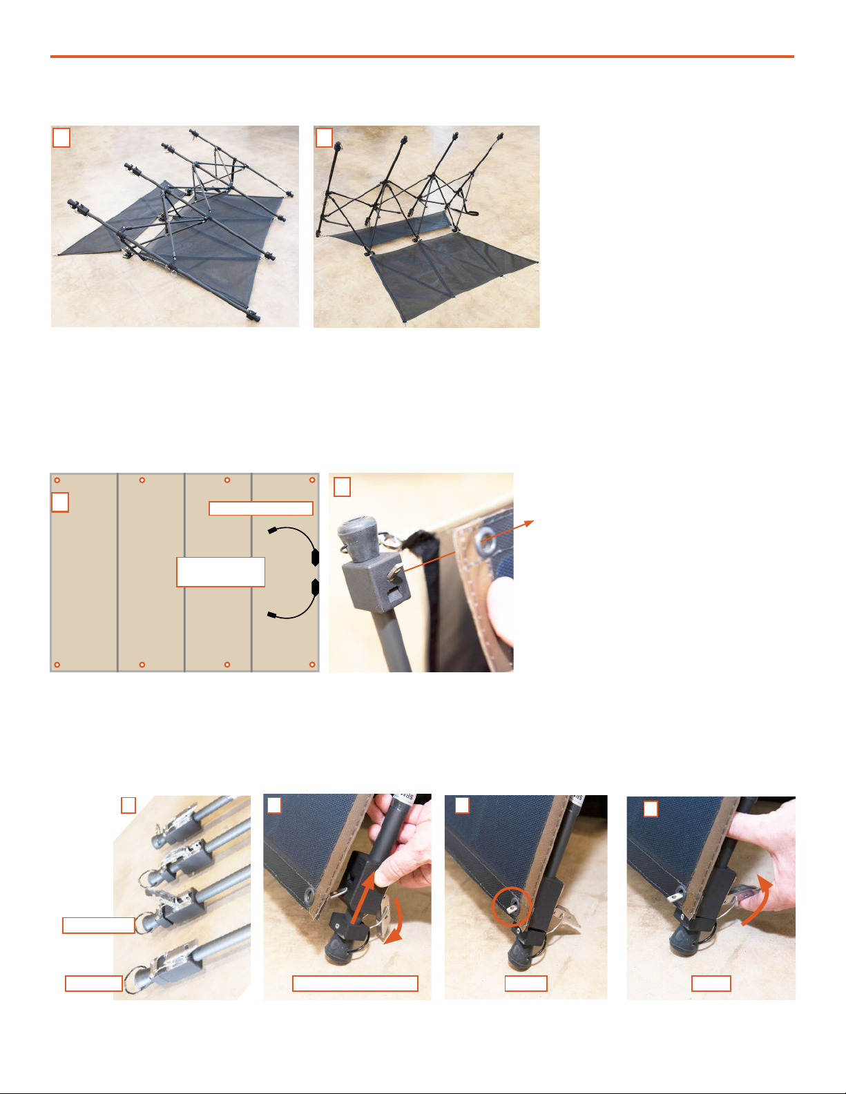
b. Mesh Configuration and Ground-securing for Flat (0º) Deployments
The Array Stand is not used when deploying the Array at 0º, or at. Instead, the 30º and 60º Mesh
pieces are connected to the back side of each Solar Panel and then to each other to form a “pouch”
into which sandbags are inserted. The number of sandbags required to secure the Array will vary by
terrain and environmental conditions.
DO NOT kneel on or place weight on the Solar Panel while installing
the ground securing Mesh as Panel cells may be damaged. If a suitable
working surface is not available, connect the Meshes with Panels standing
on edge.
1. Place Panel solar cell-side (“face”) down on a surface that will not damage
the solar cells/Panel. Place the ground-securing Mesh (nylon strap side
up) on the back of the Panel as shown in Figure 9B. The smaller of the two
Meshes must be on top of the larger one.
2. Slide the looped wire through the grommet then secure in the clip (Figure 9A). Repeat step for
each of the eight (8) points of connection [four (4) on each section of Mesh; orange boxes in B].
3. Secure the nylon strap into the clip (Figure 9C). Repeat step for each of the three (3) points of
connection in the middle of the Panel (orange circles in B)
Figure 9. Conguring ground-securing Mesh for at (0º) deployment
A
4. Flip over Panel so Mesh is on underside.
5. Place sandbags between Mesh and Panel.
Figure 10. Sandbags placement for 0º deployment
BC

Operation and Maintenance Manual for the Solar Venture 320 W Array
12 |
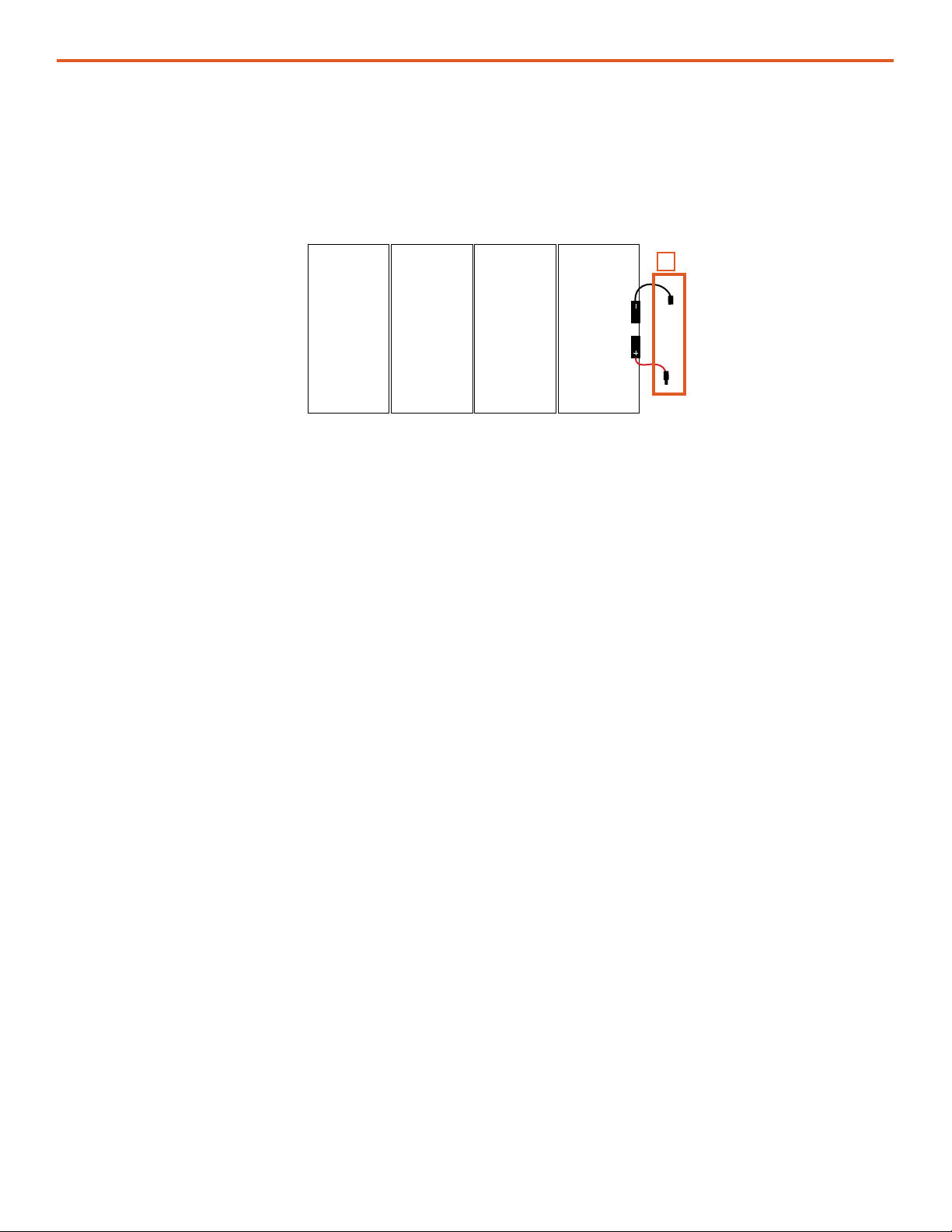
8. Connect Solar Cable to Solar Array Leads
Connect the leads on each Panel to the Solar Cable as illustrated below in (Figure 11). The
connectors on both ends of the Cable are polarized to prevent improper connection.
Figure 11. Connecting Array to Solar Cable.
320W Solar Array
Power Hub
Connector
9. Connect Array(s) to Power Hub
Connect Solar Cable to the solar power input ports on the side of the Power Hub. The Solar Array
must be within 35 ft. of the Power Hub as this is the length of the Solar Cable (32 ft. Solar Cable plus
3 ft. of cable connected to each of the panels). Do not secure Array to the ground until adequate
cable length to the Power Hub has been veried and Array have been oriented optimally toward the
sun.

| 13
Operation and Maintenance Manual for the Solar Venture 320 W Array
Array Orientation for Optimum Power Generation
Power generation requires direct sunlight for maximum performance. Optimal power generation is
achieved by orienting all Array in the same direction and at the same angle.
Note: Harvesting energy will not improve by orienting subsets of Array to capture morning,
midday, and evening sun. In the Northern Hemisphere, the Array should be positioned so that
they face the noon sun, which is usually true south in the Northern Hemisphere and true north if
in the Southern Hemisphere. The Array may also be deployed at and aimed straight up when
conditions warrant.
Seasonal Adjustment of Array Tilt to Improve Output
Array performance may be improved by adjusting the tilt and orientation of the Panels seasonally.
The angle of the Array, relative to the sun, can be adjusted to 0º, 30° or 60° prior to securing to the
ground. In the Northern Hemisphere, the sun is higher overhead during the summer and lower on
the horizon during the winter.
Power output of Array can be monitored in real time on the Power Hub User Interface. (See Power
Hub Operator Manual for instructions.) Monitoring the power output while orienting and choosing
the best tilt angle for the Panels will assist in nding and maintaining optimum power output
throughout the year.
10. Position Array for Optimal Power Generation
Shading
The Array must be positioned so they are not shaded. During periods of inclement weather or if the
Array is not positioned optimally, daily power generation levels may be reduced.
The setup location should have good exposure to sunlight and be away from other structures or
potential hazards such as vehicle thoroughfares.
Disconnecting Array
To disconnect MC4 connectors, squeeze locking tabs and pull apart. Solar Panels should not be
disconnected when under load because doing so could produce arc ash. Solar Panels produce
electricity when exposed to light. Options for eliminating the load include: placing panel “face down”
on an a at surface, waiting until night time, or covering the panel with an opaque material. If none
of these is a reasonable option, disconnect the MC4 connectors very slowly while wearing insulated
gloves and protective eye wear. Disconnecting slowly signicantly reduces the potential for arc ash
and ensures that if it occurs, it will be contained within the insulating shield of the MC4 connector.
Derating, Solar Loading, and Airflow
Derating occurs when the power output is diminished below rated values. Array may accumulate
excessive amounts of heat due to solar loading and lack of airow, resulting in derating.
Locate Array where airow is unobstructed to reduce the impact of solar loading–induced derating.
Operation and Maintenance Manual for the Solar Venture 320 W Array
14 |
Figure 12. Packing Solar Venture 320 W Array
Stowing Array
Pack Solar Array components into the hard case as illustrated below.
1. Place Solar Panel in bottom of compartment.
2. Place Solar Array Stand on top of Solar Panel.
3. Place Quick Reference on Array Support Frames.
4. Place Solar Cable in compartment on left.
5. Place Ground Securing Kit components into indicated compartments.
a. Large Ground Securing Mesh (x1)
b. Small Ground Securing Mesh (x1)
c. Sandbags (x7)
6. Close and lock case lid.

| 15
Operation and Maintenance Manual for the Solar Venture 320 W Array
• Check panels daily to ensure they are generally free of dust, dirt and debris. Spray the panels
with water or remove dust and dirt using a wet, clean microber cloth once a month or as
needed. The panels may require more frequent cleaning in extremely dirty environment. Do not
use any chemicals when cleaning the panels.
• Position Array for maximum daily sunlight exposure.
• Secure Solar Cables and provide strain relief at locations where cables are stressed.
• Check the integrity of electrical connectors monthly.
• Maintain adequate airow around Array to minimize derating.
MAINTENANCE
TROUBLESHOOTING
The Solar Venture 320 W Array provides regulated power via the Power Hub. The contribution of
solar power generation should be monitored over time to ensure optimal performance of the Array.
If a decrease in performance is observed during normal operation, the source of the issue may be
determined by measuring the voltage of each Array independently using a handheld multimeter
(Figure 13).
It is important to remember that the charging current from the Array reported at the Power
Hub will be low, even in full sun, when the System batteries are at or near a full charge. This is
a normal operating condition.
Measuring Array Voltages: Background
Voltage “open circuit” (Voc )is unregulated Array voltage and is measured directly from the leads of
an Array when not connected to a “load” such as a charge controller (Power Hub). The rated Voc of
the Solar Venture 320 W Array is approximately 62 V under standard test conditions (STC).
When the Array is connected to the Power Hub (i.e., the Array is connected to a “load”), it is more
likely the operator will see voltages around 45–55 Voltage Max Power (Vmp) reported on the User
Interface.
The Voc and Vmp should be measured for each Solar Array in “ideal” conditions if possible. This
means the Array should be oriented directly at the sun and unshaded on a clear day to measure Vmp
and Voc.
Operation and Maintenance Manual for the Solar Venture 320 W Array
16 |
Procedure to Measure Array and Panel Voc with a Multimeter
To measure Panel Voc, disconnect the Solar Cable from Array leads and carefully place the meter
probes into the Array lead connectors (orange boxes in Figure 13A).
Figure 13. Measuring Solar Panel and Array open circuit voltage Voc
320W Array
A
Array and Panel Short Circuit Current.
The Short Circuit Current (Isc) is the value of current measured with a multimeter connected to the
positive and negative terminals of a Solar Array. This is the highest current the Solar Array will
produce under standard test conditions.
| 17
Operation and Maintenance Manual for the Solar Venture 320 W Array
TECHNICAL SPECIFICATIONS
Includes
(1) 320W Foldable Solar Panel (PN: 14-1000037)
(1) Solar Venture Array Stand (PN: 14-1000033)
(1) 30’ Solar Cable (PN: 16-0800102)*
(1) Ground Securing Kit (PN: 12-1000009)**
(1) Transport Case (hard or soft case)
Hard Case, Solar Venture (PN: 14-1000035)
Soft Case, Solar Venture (PN: 14-1000040)
* Solar Cables in different lengths, sizes, and types also available
** Includes (1) 30º mesh, (1) 60º Mesh, and (7) sandbags
Weights and Dimensions (L x W x H)
Solar Panel Weight 12.9 lb (5.86 kg)
Solar Panel Dimensions
Deployed (Open): 65.125 x 43.25 x 0.2 in
(165.4175 x 109.855 x 0.508 cm)
Stowed (Folded): 16.5 x 43.25 x 1.5 in
(41.91 x 109.855 x 3.81 cm)
Panel Stand Weight 13.0 lb. (5.91 kg)
Panel Stand Dimensions
Deployed @ 30º: 65.25 x 36 x 23.5 in
(165.735 x 91.44 x 59.69 cm)
Deployed @ 60º: 65.25 x 23.5 x 36 in
(165.735 x 59.69 x 91.44 cm)
Stowed: 47 x 13.375 x 3.5 in
(119.38 x 33.97 x 8.89 cm)
Deployment Footprint 16.3 square feet @ 30º
10.65 square feet @ 60º
Transport Weight
Hard case:
64 lb (29.03 kg)
Soft case:
40 lb (18.14 kg)
Transport Dimensions
Hard Case: 49.7 x 21.5 x 8.87 in
(126.24 x 54.61 x 22.53 cm)
Soft Case: 50 x 17 x 8 in
(127 x 43.18 x 20.32 cm)
Environmental
Operating Temperature -25 ºF to +140 ºF (-31.7 ºC to +60 ºC
Storage Temperature -40 ºF to +160 ºF (-40 ºC to +71.1 ºC)
Maximum Wind Load
30° front, up to 75 mph
30° back, up to 65 mph
60° front, up to 70 mph
60° back, up to 60 mph
Solar Panel @ 77 °F (25 °C)
Rated Power 320 W (+/-2W)
Rated Voltage (VMP)58.75 V
Open Circuit Voltage (VOC)68.45 V
Rated Current (IMP)5.79 A
Short Circuit Current (ISC)6.28 A
Cell Type Monocrystalline silicone
Cell Efficiency > 24.1%
# of Solar Cells 96
Power Circuitry Series
Bypass Diode 16 embedded
Blocking Diode 1 in junction box
Temperature Co-efficiency -0.3%C
Connections
Solar Panel (1) MC4 male and (1) MC4 female
Solar Cable (1) MC4 male and (1) MC4 female for connection to solar panel
(1) Bayonet for solar array output
General
Solar Panel Construction Back Side: Tan fabric
Panel Support: Carbon fiber composite
Panel Stand Construction Stainless steel/Aluminum/Injection molded plastic
Transport Soft Case
Construction
Hard Case: Durable MIL-SPEC plastic with foam inserts and
carrying handles
Soft Case: Water resistant nylon fabric with carrying strap
Ground Securing Nylon meshes with tie downs under sandbags
Solar Cable 6AWG wire with MIL-SPEC connectors
Deployment Angles 30º, 60º
Certifications
Berry Amendment compliant
Solar modules designed to UL 1703 and IEC-61215
Designed to MIL-STD-810H
Warranty 1-year materials and workmanship

Operation and Maintenance Manual for the Solar Venture 320 W Array
18 |

| 19
Operation and Maintenance Manual for the Solar Venture 320 W Array
ABOUT SOLAR STIK, INC.
Mission Statement
Saving lives across the globe through innovative power solutions.
STIKopedia
STIKopedia is a compilation of everything you would ever want to know about portable Hybrid
Power Systems, including the philosophy and mechanics of high-efciency circuits, and the
individual technologies used to create them.
Solar Stik Training and Education
• Solar School (St. Augustine, FL) provides an introduction to the design and support of small-
scale, renewable-energy, power generation systems, with detailed explanation of system
components. Advanced conguration options with hands-on deployment of actual systems will
enhance student understanding.
• Solar Stik New Equipment Training (on site) teaches Hybrid System conguration options with
hands-on deployment of actual systems to enhance student understanding.
Solar Stik Training Courses are tailored to the specic needs of the students. To schedule Solar Stik
Training or to learn more about the curriculum, please contact us.
Contact
Tech Support (24/7)
(800) 793-4364 x102
Tech Support (Outside of the US) (24/7)
+1 (904) 808-0510 x102
Address
Solar Stik, Inc.
13 N Leonardi Street
Saint Augustine, Florida 32084
Website
www.solarstik.com
Trademarks and Logos are the property of Solar Stik, Inc. unless otherwise noted.
This manual is subject to revisions without prior notice.
© 2023 Solar Stik, Inc.
All Rights Reserved.
Table of contents
Other Solar Stik Solar Panel manuals


