Solar Stik SOLAR VENTURE 300W PHOTOVOLTAIC ARRAY Installation instructions
October 2020
OPERATOR AND MAINTENANCE MANUAL
FOR THE
SOLAR VENTURE 300W
PHOTOVOLTAIC ARRAY
P/N 19-1000010
DISTRIBUTION STATEMENT A. Approved for public release; distribution is unlimited.
Updated:2020108
Version 1.0
Solar Venture 300W PV Array Operator and Maintenance Manual
October 20202 |
Contents
GENERAL INFORMATION, THEORY OF OPERATION, AND EQUIPMENT DESCRIPTION
Introduction . . . . . . . . . . . . . . . . . . . . . . . . . . . . . . . . . . . . . . . . . . . . . . . . . . . . . 4
Product Safety Information and Instructions . . . . . . . . . . . . . . . . . . . . . . . . . . . . . . . . . . . 5
Safety Information Labels . . . . . . . . . . . . . . . . . . . . . . . . . . . . . . . . . . . . . . . . . . . . . 5
Fire Hazard . . . . . . . . . . . . . . . . . . . . . . . . . . . . . . . . . . . . . . . . . . . . . . . . . . . . 6
Recommended Fire Extinguisher . . . . . . . . . . . . . . . . . . . . . . . . . . . . . . . . . . . . . . . . . 6
Electric Shock Hazard Related to PV Panels . . . . . . . . . . . . . . . . . . . . . . . . . . . . . . . . . . . 7
Environmental and Handling Precautions . . . . . . . . . . . . . . . . . . . . . . . . . . . . . . . . . . . . . 8
Wind . . . . . . . . . . . . . . . . . . . . . . . . . . . . . . . . . . . . . . . . . . . . . . . . . . . . . . . .8
Water . . . . . . . . . . . . . . . . . . . . . . . . . . . . . . . . . . . . . . . . . . . . . . . . . . . . . . . 8
Impact . . . . . . . . . . . . . . . . . . . . . . . . . . . . . . . . . . . . . . . . . . . . . . . . . . . . . . .8
Dust . . . . . . . . . . . . . . . . . . . . . . . . . . . . . . . . . . . . . . . . . . . . . . . . . . . . . . . . 8
Heat . . . . . . . . . . . . . . . . . . . . . . . . . . . . . . . . . . . . . . . . . . . . . . . . . . . . . . . . 8
Theory of Operation . . . . . . . . . . . . . . . . . . . . . . . . . . . . . . . . . . . . . . . . . . . . . . . . . 9
Equipment Description . . . . . . . . . . . . . . . . . . . . . . . . . . . . . . . . . . . . . . . . . . . . . . 10
Kit Components . . . . . . . . . . . . . . . . . . . . . . . . . . . . . . . . . . . . . . . . . . . . . . . . . 10
OPERATOR INSTRUCTIONS
Solar Venture 300W PV Array Setup . . . . . . . . . . . . . . . . . . . . . . . . . . . . . . . . . . . . . . . 11
Position and Orient System Components. . . . . . . . . . . . . . . . . . . . . . . . . . . . . . . . . . . . 11
Deploy the PV Array Support Frame . . . . . . . . . . . . . . . . . . . . . . . . . . . . . . . . . . . . . . 12
Install the Large Ground-securing Mesh . . . . . . . . . . . . . . . . . . . . . . . . . . . . . . . . . . . . 13
Install the Small Ground-securing Mesh . . . . . . . . . . . . . . . . . . . . . . . . . . . . . . . . . . . . 14
Install the PV Array on the Support Frame . . . . . . . . . . . . . . . . . . . . . . . . . . . . . . . . . . . 16
Connect the Solar Cable to the PV Panel Leads . . . . . . . . . . . . . . . . . . . . . . . . . . . . . . . . 17
Connect PV Array(s) to Solar Only Input Port of Power Hub . . . . . . . . . . . . . . . . . . . . . . . . . . 18
Position the PV Arrays for Optimal Power Generation . . . . . . . . . . . . . . . . . . . . . . . . . . . . . 19
Derating, Solar Loading, and Airflow. . . . . . . . . . . . . . . . . . . . . . . . . . . . . . . . . . . . . . . 19
Secure the Array to the Ground. . . . . . . . . . . . . . . . . . . . . . . . . . . . . . . . . . . . . . . . . . 20
Disassembling and Repacking the PV Array . . . . . . . . . . . . . . . . . . . . . . . . . . . . . . . . . . 21
MAINTENANCE
Preventive Care and Maintenance . . . . . . . . . . . . . . . . . . . . . . . . . . . . . . . . . . . . . . . . 22
PV Array Conditional Maintenance . . . . . . . . . . . . . . . . . . . . . . . . . . . . . . . . . . . . . . . . 22
Measuring PV Array Voltages: Background . . . . . . . . . . . . . . . . . . . . . . . . . . . . . . . . . . . 22
Procedure to Measure PV Array Voc with a Multimeter . . . . . . . . . . . . . . . . . . . . . . . . . . . . . 23
SUPPORTING INFORMATION
Technical Specifications . . . . . . . . . . . . . . . . . . . . . . . . . . . . . . . . . . . . . . . . . . . . . 24
ABOUT SOLAR STIK, INC.
Contact . . . . . . . . . . . . . . . . . . . . . . . . . . . . . . . . . . . . . . . . . . . . . . . . . . . . . . . 27

| 3October 2020
Solar Venture 300W PV Array Operator and Maintenance Manual
List of Figures
Figure 1. Solar Venture 300W PV Array with ground securing ......................................................................................... 4
Figure 2. Solar Venture 300 W PV array with a small HPS ............................................................................................... 9
Figure 3. Solar Venture 300W PV Array components in transport case (top) and unpacked (bottom) .......................... 10
Figure 4. Working-space radius for the PV arrays and associated equipment .............................................................. 11
Figure 5. Deploying the PV array support frame ............................................................................................................ 12
Figure 6. Large ground-securing mesh installation ........................................................................................................ 13
Figure 7. Small ground-securing mesh installation ........................................................................................................ 14
Figure 8. Ground-securing mesh conguration for 30º array deployment ..................................................................... 15
Figure 9. Ground-securing mesh conguration for 60º array deployment ..................................................................... 15
Figure 10. Connecting array hooks to support frame..................................................................................................... 16
Figure 11. Locking the array into place on the support frame ....................................................................................... 16
Figure 12. Connecting the PV array to the Solar Cable.................................................................................................. 17
Figure 13. PV arrays connected to Solar Only Input ports of Power Hub ..................................................................... 18
Figure 14. Ground-securing sandbag placement .......................................................................................................... 20
Figure 15. Packing the Solar Venture 300W PV Array.................................................................................................... 21
Figure 16. Measuring PV array open circuit voltage Voc ................................................................................................ 23
Section Page(s) Description Date
Published June 2020
Revision History

Solar Venture 300W PV Array Operator and Maintenance Manual
October 20204 |
Introduction
The Solar Venture 300W Photovoltaic (PV) Array is designed to generate renewable power in
expeditionary applications where weight, rugged design, and extreme portability are factors.
The Venture design can be deployed on any terrain, and the PV array can generate up to 300 Watts
of power for applications where independence from traditional power sources is required:
• PV power generation for remote locations where fuel-driven generators are not an option
• Decreased fuel consumption in a Hybrid Power System (HPS)
• Peak-shaving to decrease reliance on power from utility or grid
The Solar Venture 300W PV Array is modular and scalable, allowing users to tailor power generation
capability to load requirements.
Setup requires no tools and the 300 W Array is “Plug & Play” compatible with Hybrid Power
Systems.
The mono-crystalline cells in the high efciency Venture-Series panels are laminated onto a carbon-
ber structure, which combines extremely high PV performance with incredibly light material for
an extraordinary watt-to-weight ratio. The Venture offers a superior integration of technologies to
provide the operator with highest power in the smallest renewable generator footprint.
Figure 1. Solar Venture 300W PV Array with ground securing
GENERAL INFORMATION, THEORY OF OPERATION, AND
EQUIPMENT DESCRIPTION

| 5October 2020
Solar Venture 300W PV Array Operator and Maintenance Manual
Your safety and the safety of others is very important. This manual provides guidance on safe
operating practices and how to achieve maximum performance from the Solar Venture 300W PV
Array. Always observe and follow all safety protocols outlined below:
This is the safety alert symbol. This symbol alerts you to potential hazards that can kill you or
hurt you and others. All safety messages will follow the safety alert symbol and the word
“DANGER”, “WARNING”, or “CAUTION”. These words are dened as:
DANGER Indicates a hazardous situation which, if not avoided, will result in death or
serious injury.
WARNING Indicates a hazardous situation which, if not avoided, could result in death or
serious injury.
CAUTION Indicates a hazardous situation which, if not avoided, could result in minor or
moderate injury.
All safety messages will identify what the potential hazard is, how to reduce the chance of injury, and
what can happen if the instructions are not followed.
Product Safety Information and Instructions
This manual contains important safety instructions that must be followed during the installation and
operation of the PV array. Read all instructions and safety information contained in this manual.
Exercise caution when handling or operating equipment. Live power may be present.
Safety Information Labels
Solar Venture 300W PV Array Operator and Maintenance Manual
October 20206 |
Fire Hazard
Fire Types
Class A fire - Fires in ordinary combustibles such as wood, paper, cloth, trash, and plastics.
Class B fire - Fires in ammable liquids such as gasoline, petroleum, oil, and paint.
Class C fire - Fires involving energized electrical equipment such as motors, transformers, and
appliances. Remove the power source and the class C re becomes a class A or B re.
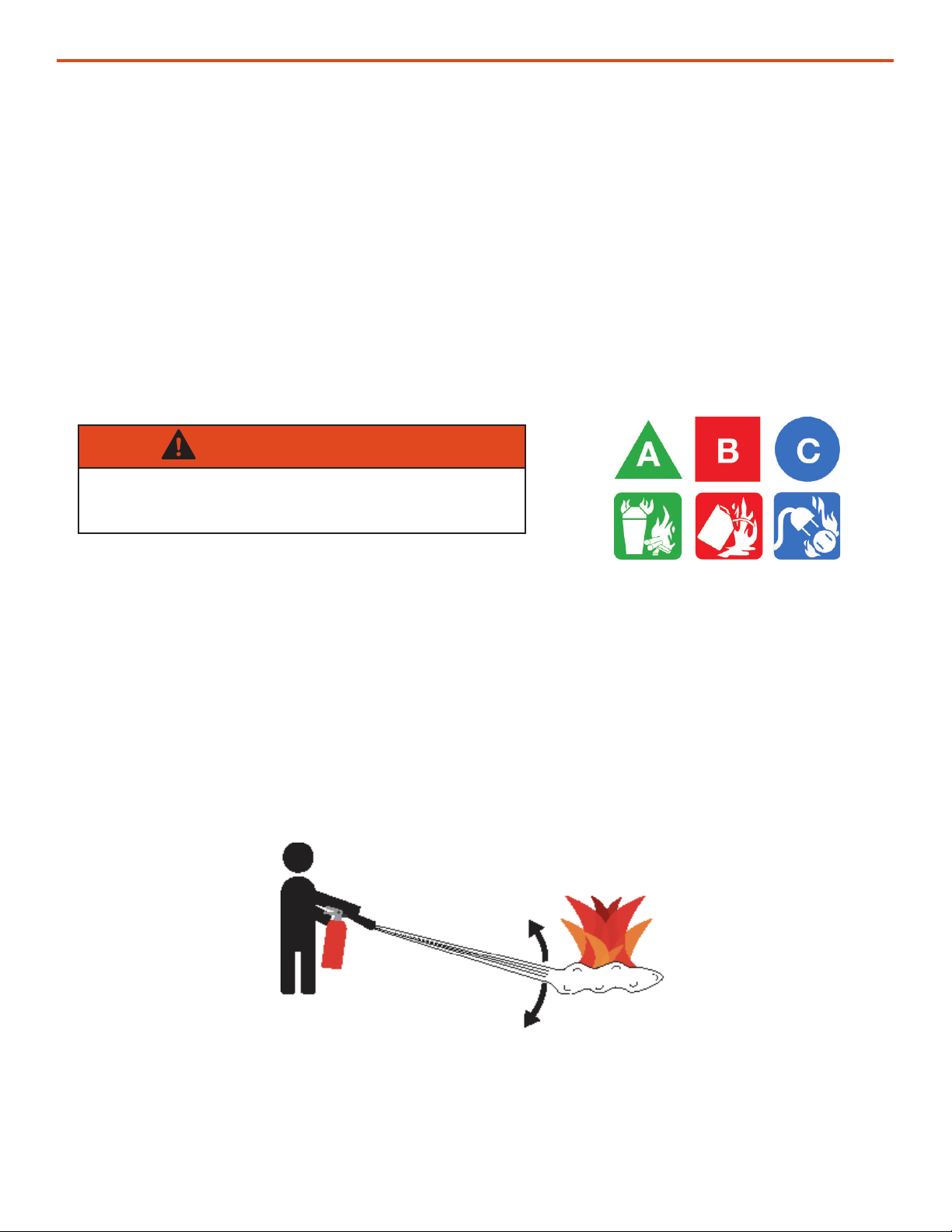
Recommended Fire Extinguisher
NSN 4210-00-288-7219 Fire Extinguisher, Carbon Dioxide, 10 lb
Carbon dioxide is a liqueed gas, which is highly effective ghting class B and C res. These
extinguishers are ideal for areas where contamination and/or cleanup are a concern, such as data
processing centers, labs, and telecommunication rooms.
Use Sweeping Motion
WARNING
Only CO2(carbon dioxide) re extinguishers should
be used with this equipment.
Using the Fire Extinguisher
When using the extinguisher on a re, remember PASS:
Pull the pin.
Aim the nozzle or hose at the base of the re from a safe distance.
Squeeze the operating lever to discharge the re extinguishing agent.
Sweep the nozzle or hose from side to side until the re is out. Move forward or around the re as
the re diminishes.
Watch the area for reignition until the cause has been xed.

| 7October 2020
Solar Venture 300W PV Array Operator and Maintenance Manual
Electric Shock Hazard Related to PV Panels
WARNING
Standing water around the electrical equipment and/or intrusion of water into the System
components can increase the risk of electrical shock.
DON’T LET THIS BE YOU!
HIGH VOLTAGE: PV arrays and generators produce potentially lethal line voltages. When servicing
equipment, extreme care should be taken to protect against electrocution. Always work with another
person in case an emergency occurs. Disconnect power before checking controllers or performing
maintenance. Be sure the generator is properly grounded. Wear safety glasses whenever working on
any part of the System that requires exposure to mechanical or direct electrical contacts.
• PV panels produce electricity when exposed to sunlight.
• Live power may be present at multiple terminals.
• Never route the cables through standing water.
• All cables and connections should remain dry and should be inspected regularly to ensure safe
operating conditions.

Solar Venture 300W PV Array Operator and Maintenance Manual
October 20208 |
Environmental and Handling Precautions
This equipment is ruggedized, yet there are a few things the operator can do to prevent failures and
prolong the operational life of the product.
Water
• Do not operate equipment in or around standing water.
• Do not place cables that conduct electricity in or near
standing water.
Impact
The PV panels should be protected from being struck by
hard objects.
Dust
• This equipment is designed for operation in climates
where high levels of dust or other particulates may
exist.
• Clean the surface of the PV panels regularly to maintain
maximum output. Dirty panels produce less power.
Heat
• Heat and solar loading reduce efciency and life
expectancy. Shade products (except PV panels) to
prevent the negative effects of heat.
• PV panels should be placed so that they are exposed
to adequate airow.
Wind
It is imperative to properly secure the PV panels to
the ground using sandbags so they do not become
dangerous projectiles in high winds.
| 9October 2020
Solar Venture 300W PV Array Operator and Maintenance Manual
PV cells convert sunlight into electrical power. All PV cells are made of materials called
semiconductors that absorb photons when sunlight strikes the PV cell. The absorbed photons
then knock electrons loose within the PV cells, allowing them to ow, which produces an electrical
current. PV cells contain one or more electric elds that force the direction of electron ow. Placing
metal contacts on the top and bottom of a PV cell harnesses this current so it can power external
appliances, much like a traditional power generator.
On their own, PV cells produce a limited amount of power, but when arranged and electrically
connected in a PV panel, the power generated is directly related to how much cumulative current and
voltage the PV cell arrangement is congured for. The panel’s total output voltage and current will
determine its “watt” rating.
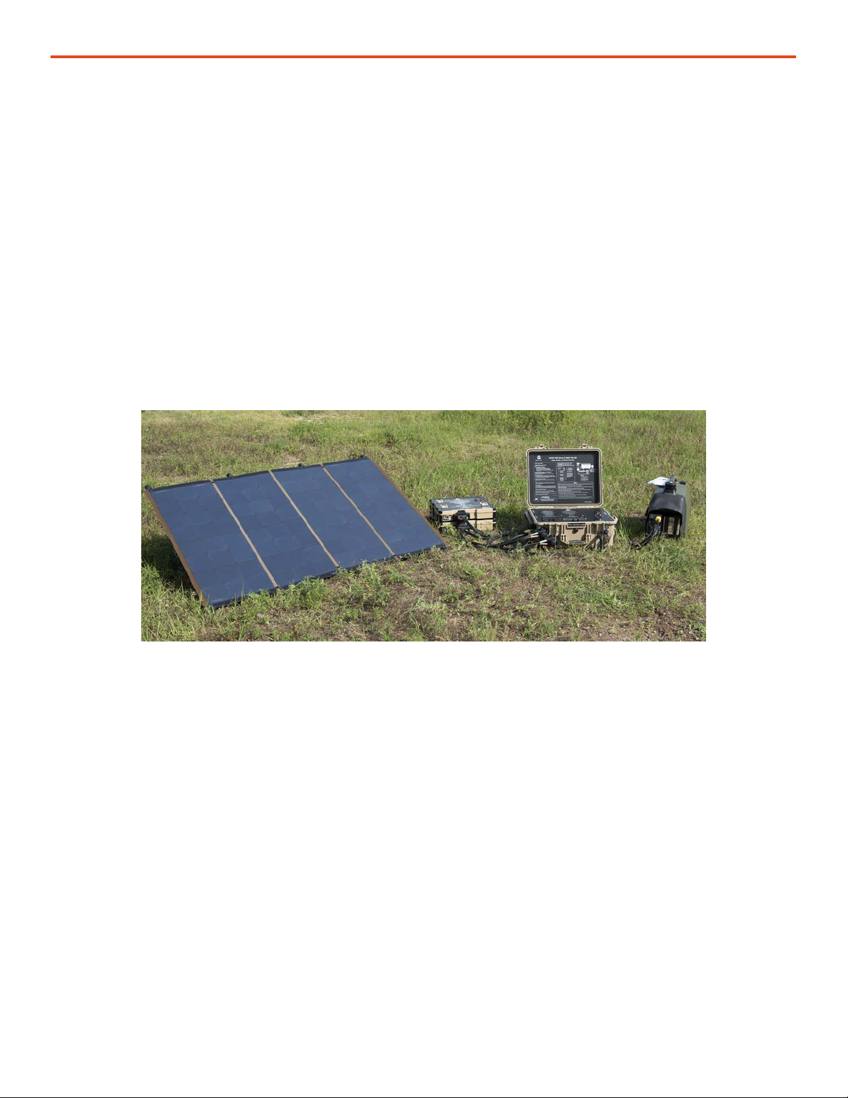
The cell conguration of the Venture 300 Array generates up to 300 W of DC power for an application.
Figure 2. Solar Venture 300 W PV array with a small HPS
Theory of Operation

Solar Venture 300W PV Array Operator and Maintenance Manual
October 202010 |
Kit Components
Solar Venture 300W PV Array
1Hard transport case
2 4-section foldable PV array
3 Ground-securing mesh (large and small)
4 Support frame
5 Sandbags (12 ea)
6Solar Cable (sold separately)
Figure 3. Solar Venture 300W PV Array components in transport case (top) and unpacked (bottom)
6
3
5
4
2
1
Equipment Description

| 11October 2020
Solar Venture 300W PV Array Operator and Maintenance Manual
Position and Orient System Components
Identify the best location for each component of the System, keeping in mind the length of all cables
that will be used to connect all of the components. The typical Solar Cable provided is 30’ long
(other lengths are available).
Figure 4. Working-space radius for the PV arrays and associated equipment
Solar Venture 300W PV Array Setup
30’
PV arrays
Power
Management/
Energy Storage
components
The PV array can be deployed within a 30’ radius (the length of the Solar Cable) of the component
to which it will be connected. If the PV array must be deployed more than 30’ from the Power Pak or
Power Hub, etc., extensions are available.
OPERATOR INSTRUCTIONS
Solar Venture 300W PV Array Operator and Maintenance Manual
October 202012 |
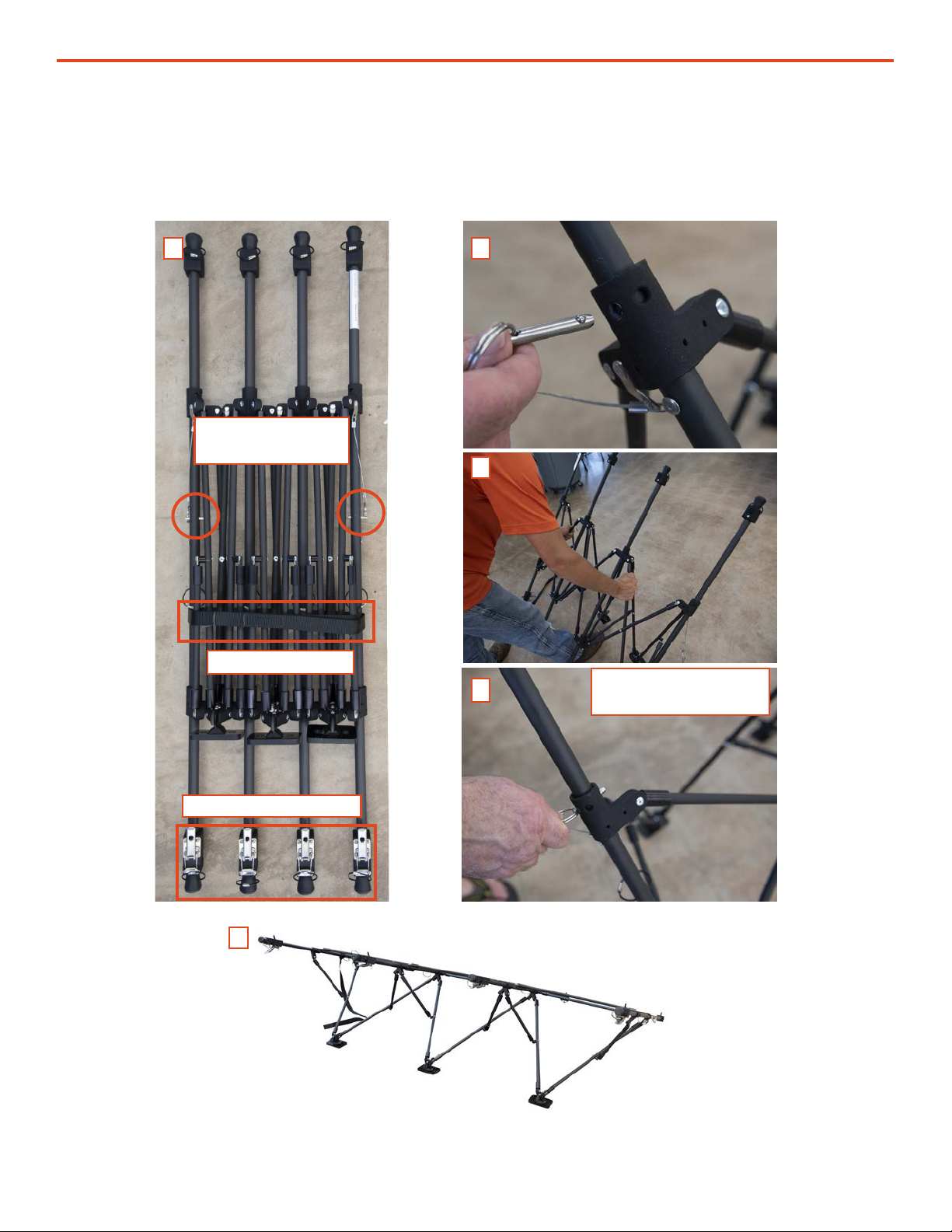
Deploy the PV Array Support Frame
Locking pins in
storage position
Transport strap
A B
C
D
E
Loosen the transport strap securing the foldable array support frame (Figure 5A). Remove the
two locking pins (Figure 5B) to allow the frame to expand. Expand the support frame (Figure 5C)
and install the locking pins in the “deployed” position (Figure 5D) after the support frame is fully
extended (Figure 5E).
Tensioning clamps
Locking pins in
deployed position
Figure 5. Deploying the PV array support frame
| 13October 2020
Solar Venture 300W PV Array Operator and Maintenance Manual
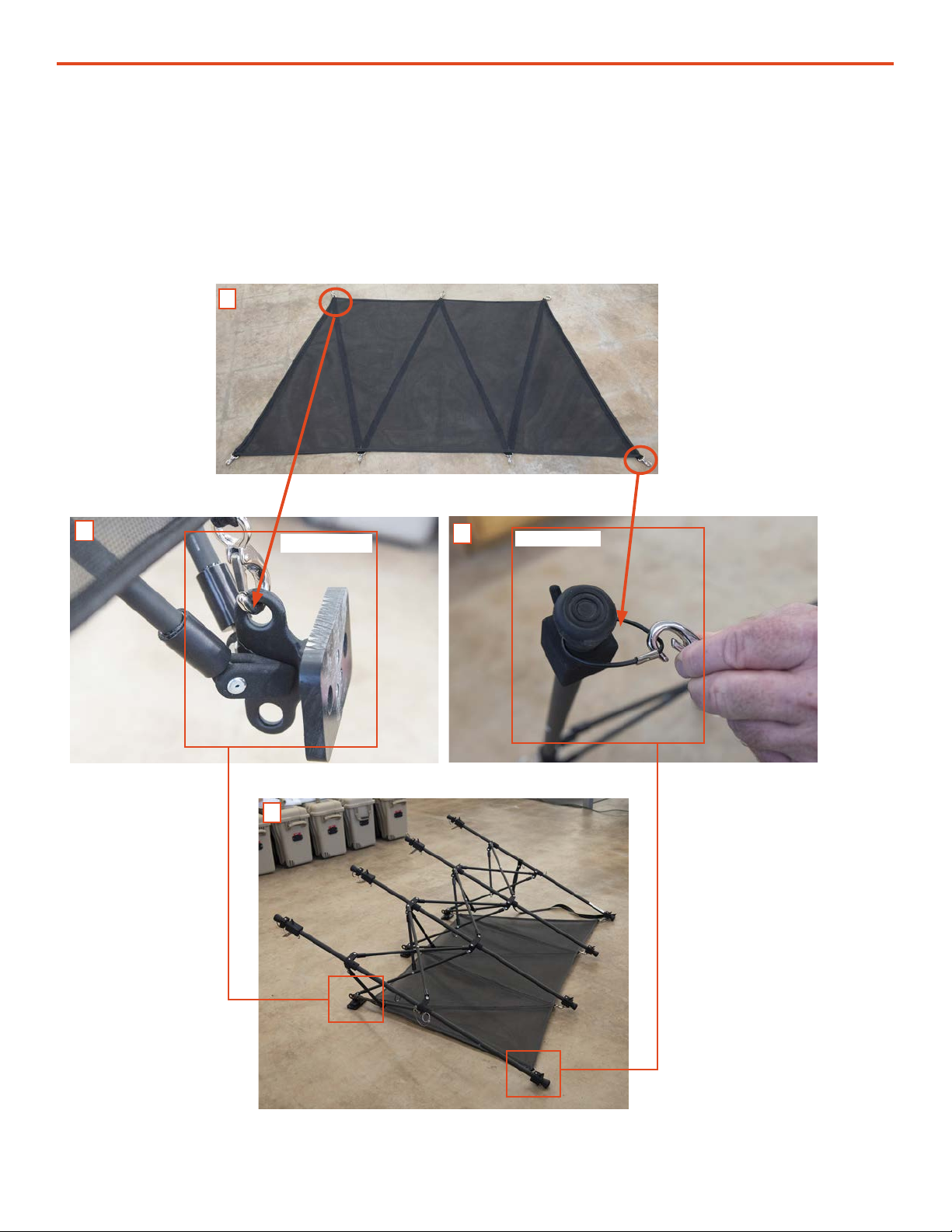
Install the Large Ground-securing Mesh
The large ground-securing mesh has three (3) clips on the short side and four (4) on the long side
(Figure 6A). The clips on the short side connect to the rings on the three (3) cleats (Figure 6B) of the
support frame. Connect the four (4) clips on the long side of the ground-securing mesh to the wire
loops (Figure 6C) at the low end of the support frame bar (Figure 6D). The mesh will be stretched
tight when all of the connections are made.
A
BC
D
Cleat rings Wire loop
Figure 6. Large ground-securing mesh installation

Solar Venture 300W PV Array Operator and Maintenance Manual
October 202014 |
Install the Small Ground-securing Mesh
The small ground-securing mesh has three (3) clips on the short side and four (4) on the long side
(Figure 7A). The clips on the short side connect to the rings (Figure 7B) on the three (3) cleats of the
support frame (Figure 7C).
Figure 7. Small ground-securing mesh installation
A
B
C
Cleat rings
| 15October 2020
Solar Venture 300W PV Array Operator and Maintenance Manual
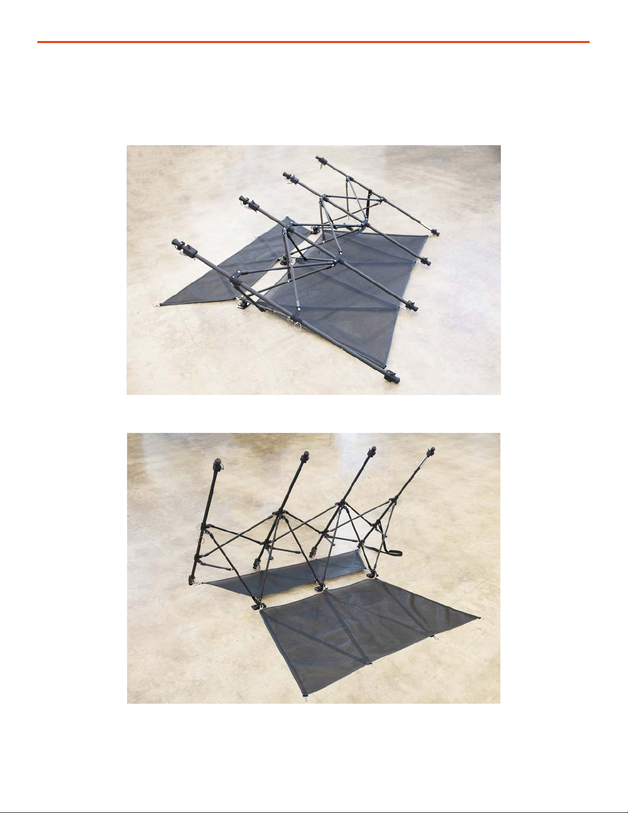
Figure 8. Ground-securing mesh conguration for 30º array deployment
Ground-securing Mesh Configuration for Low- and Steep-angle Deployments
Figure 9. Ground-securing mesh conguration for 60º array deployment
Connect the large and small ground-securing meshes as shown in Figure 8 to deploy the PV array
at 30º and as shown in Figure 9 to deploy the PV array at 60º.

Solar Venture 300W PV Array Operator and Maintenance Manual
October 202016 |
A
A B C
Install the PV Array on the Support Frame
The PV array has eight (8) grommet-reinforced holes, four (4) on the top and four (4) on the bottom
(Figure 10A, orange circles). The support frame has eight (8) complementary panel mounting hooks
(Figure 10B, orange circles). Connect the bottom of the PV array to the lower row of mounting hooks
rst and the top row of hooks second (Figure 10B).
B
Connect array to
lower hooks rst
Connect array
to upper hooks
second
The hooks on the upper row are part of a sliding tensioning clamp. Unlock and lift the clamp lever
to allow the hook to slide down (Figure 11A). Place the hook into the hole, then tighten (Figure
11B) and lock the clamp (Figure 11C). Repeat for each of the four mounting holes until the array is
secured to the support frame (Figure 11D).
Array backside
Power output
leads
D
Figure 10. Connecting array hooks to support frame
Figure 11. Locking the array into place on the support frame
| 17October 2020
Solar Venture 300W PV Array Operator and Maintenance Manual
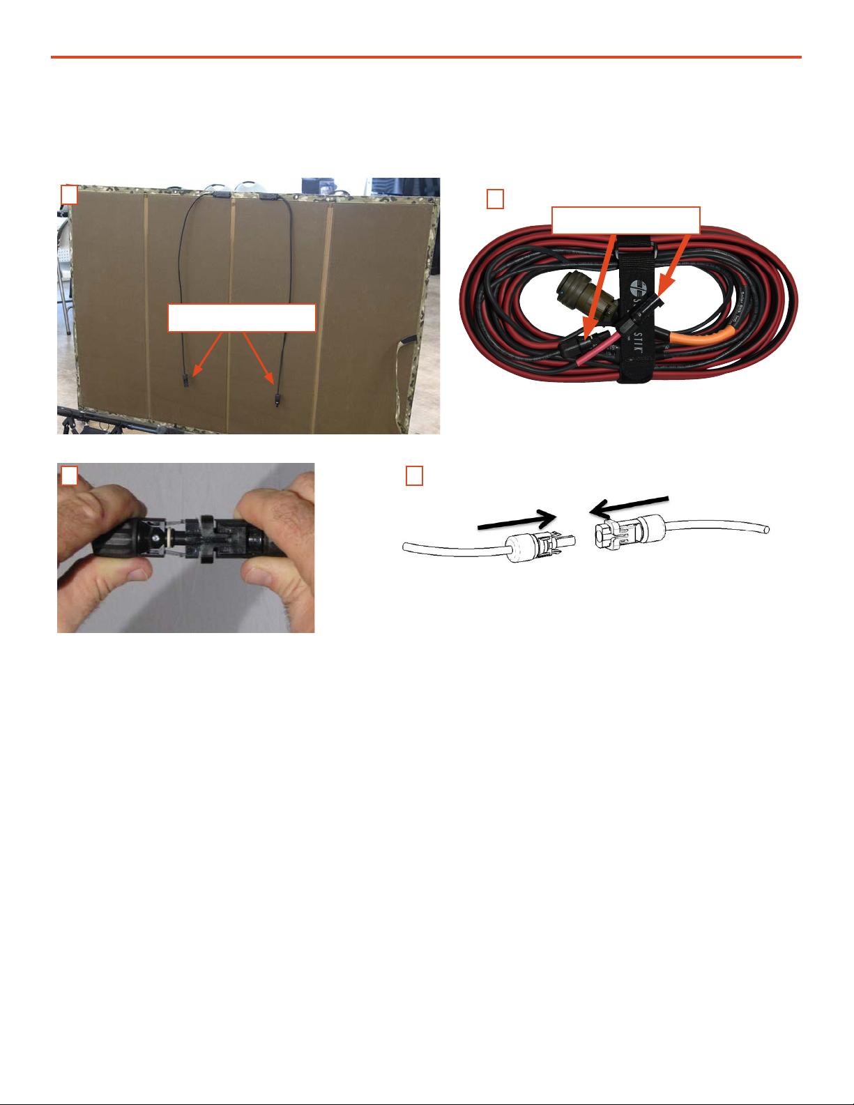
Connect the Solar Cable to the PV Panel Leads
Connectors
AB
C D
Connect the leads on the PV array (Figure 12A) to the Solar Cable (Figure 12B). The locking
connectors are polarized (Figure 12C–D).
Figure 12. Connecting the PV array to the Solar Cable.
Connectors

Solar Venture 300W PV Array Operator and Maintenance Manual
October 202018 |
Figure 13. PV arrays connected to Solar Only Input ports of Power Hub
Connect PV Array(s) to Solar Only Input Port of Power Hub
NOTICE
Do not secure the PV array to the ground until adequate cable length to the Power Hub has been
veried and the arrays have been oriented optimally toward the sun.
Connect the Solar Cable(s) to the Solar Only Input ports on the side of the Power Hub. A maximum
of six (6) PV arrays can be connected to the Power Hub.
PV arrays
Power Hub
Note: This example describes connection to a Power Hub however, other Solar Stik components
such as the PRO-Verter S, Power Paks and BOS have PV-input capabilities. Consult the Manuals for
these components for details.

| 19October 2020
Solar Venture 300W PV Array Operator and Maintenance Manual
PV Array Orientation for Optimum PV Power Generation
PV generation requires direct sunlight for maximum performance. Optimal PV power generation is
achieved by orienting all PV arrays in the same direction and at the same angle.
Note: Harvesting PV energy will not improve by orienting subsets of PV arrays to capture
morning, midday, and evening sun. In the Northern Hemisphere, the PV arrays should be
positioned so that they face the noon sun, which is usually true South, true North if in the
Southern Hemisphere. The PV arrays may be deployed at, aimed straight up if at or near the
equator.
Seasonal Adjustment of the PV Array Tilt to Improve Output
The PV array performance may be improved by adjusting the tilt and orientation of the panels
seasonally. The angle of the array, relative to the sun, can be adjusted to 30° or 60° prior to securing
to the ground. The sun is higher overhead during the summer and lower on the horizon during the
winter.
Power output of the PV arrays can be monitored in real time on the Power Hub User Interface. (See
the Power Hub Operator Manual for instructions.) Monitoring the power output while orienting and
choosing the best tilt angle for the panels will assist in nding and maintaining optimum power
output throughout the year.
Position the PV Arrays for Optimal Power Generation
NOTICE
The setup location should have good exposure to sunlight and be away from other structures or
potential hazards such as moving-vehicle thoroughfares.
Shading
The PV arrays must be positioned so they are not shaded. During periods of inclement weather or if
the array is not positioned optimally, daily power generation levels may be reduced.
Derating, Solar Loading, and Airflow
Derating occurs when the power output of the PV arrays is diminished below their rated values. PV
arrays may accumulate excessive amounts of heat due to solar loading and lack of airow, resulting
in derating.
Locate PV arrays where airow is unobstructed to reduce the impact of solar loading–induced
derating.

Solar Venture 300W PV Array Operator and Maintenance Manual
October 202020 |
The PV array must be secured with three (3) to six (6) sandbags (Figure 14) to reduce the potential
for damage in high winds.
Sandbags should weigh a minimum of 50 pounds (23 kg) each. Place sandbags on the large ground-
securing mesh under the PV panel and on the small ground-securing mesh behind the panel as
shown below (Figure 14).
Secure the Array to the Ground
WARNING
Failure to properly secure the PV array(s) to the surface with sandbags could result in PV
array damage, injury, or death in high winds. Wind damage can render arrays nonfunctional or
signicantly reduce their functional life expectancy. PV arrays must be properly secured to the
ground even in low-wind environments.
Note: Before the arrays are secured to the ground, be observant and take care to ensure
the support frame is not twisted. If the support frame is twisted, the array will be exposed to
torsional strain, which can cause damage to the cells of the array panel(s).
CAUTION
DO NOT DAMAGE THE ARRAY SUPPORT FRAME.
DO NOT DROP SANDBAGS ONTO THE PV ARRAY SUPPORT FRAME.
Figure 14. Ground-securing sandbag placement
Do not secure the arrays to the ground before establishing proper location and orientation.
This manual suits for next models
1
Table of contents
Other Solar Stik Solar Panel manuals


