SOLAR VISION ZX60 Instruction Manual
installation ManUal
ZX60 & ZX100 commercial solar lighting system
Solar Vision inc. www.solar-vision.com info@solar-vision.com T. 1-819-729-0450
Revision 3.0
IMPORTANT: Always install the system assembly on the pole before inserting the batteries.
The assembly system should never be manipulated when the batteries are installed inside.
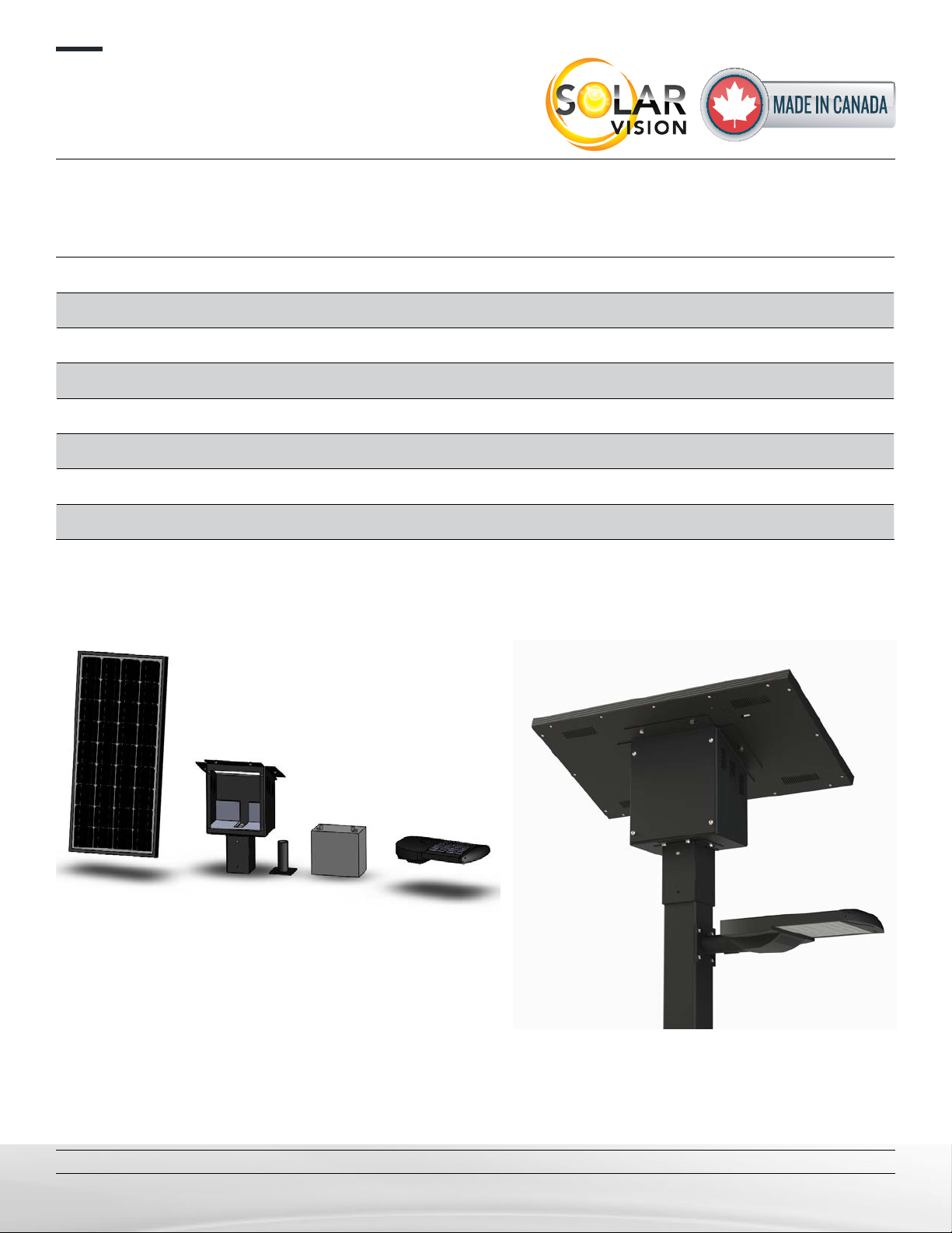
LIST OF MATERIAL
A) Solar module with integrated control system and wiring. (1 per system)
B) Battery main enclosure (1 per system)
C) Battery, 12V (1 per system)
D) Stainless Steel Hardware, 1/4”-20 (ZX60) or 5/16”-18 (ZX100) for system assembly
E) LED Luminaire (12Vdc compatible only)
F) Luminaire mounting tenon (hardware 5/16-18x1” included)
Note : The ZX system operates at 12Vdc. Other voltage will damage system.
ZX SYSTEM COMPONENTS ZX FINAL ASSEMBLY
P.1/10
installation ManUal
ZX60 & ZX100 commercial solar lighting system
Solar Vision inc. www.solar-vision.com info@solar-vision.com T. 1-819-729-0450
Revision 3.0
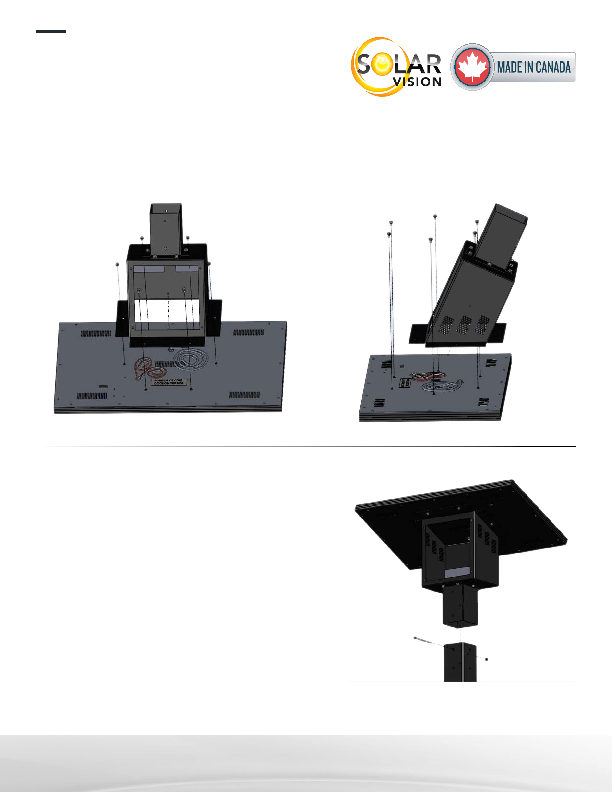
STEP 1:
Using the supplied 1/4”-20 (ZX60) bolts or the 5/16”-18 (ZX100) bolts and hardware (hex bolt, lock
washer, at washer), fasten the battery compartment to the solar module as indicated on the image.
Orientation of the battery box is critical, use the “Door on this Side” sticker to conrm orientation.
Step 2: Find the optimal system orientation
a) First determine the system orientation so that the solar
module faces true south.
b) Use the drill guide at the end of the document to drill the
pole at the appropriate locations.
c) Install the system on the pole. Use the 1/4”-20 bolt and
hardware (bolts, at washer, lock washer and nut) through
the pole to secure in place.
P.2/10
installation ManUal
ZX60 & ZX100 commercial solar lighting system
Solar Vision inc. www.solar-vision.com inf[email protected] T. 1-819-729-0450
Revision 3.0
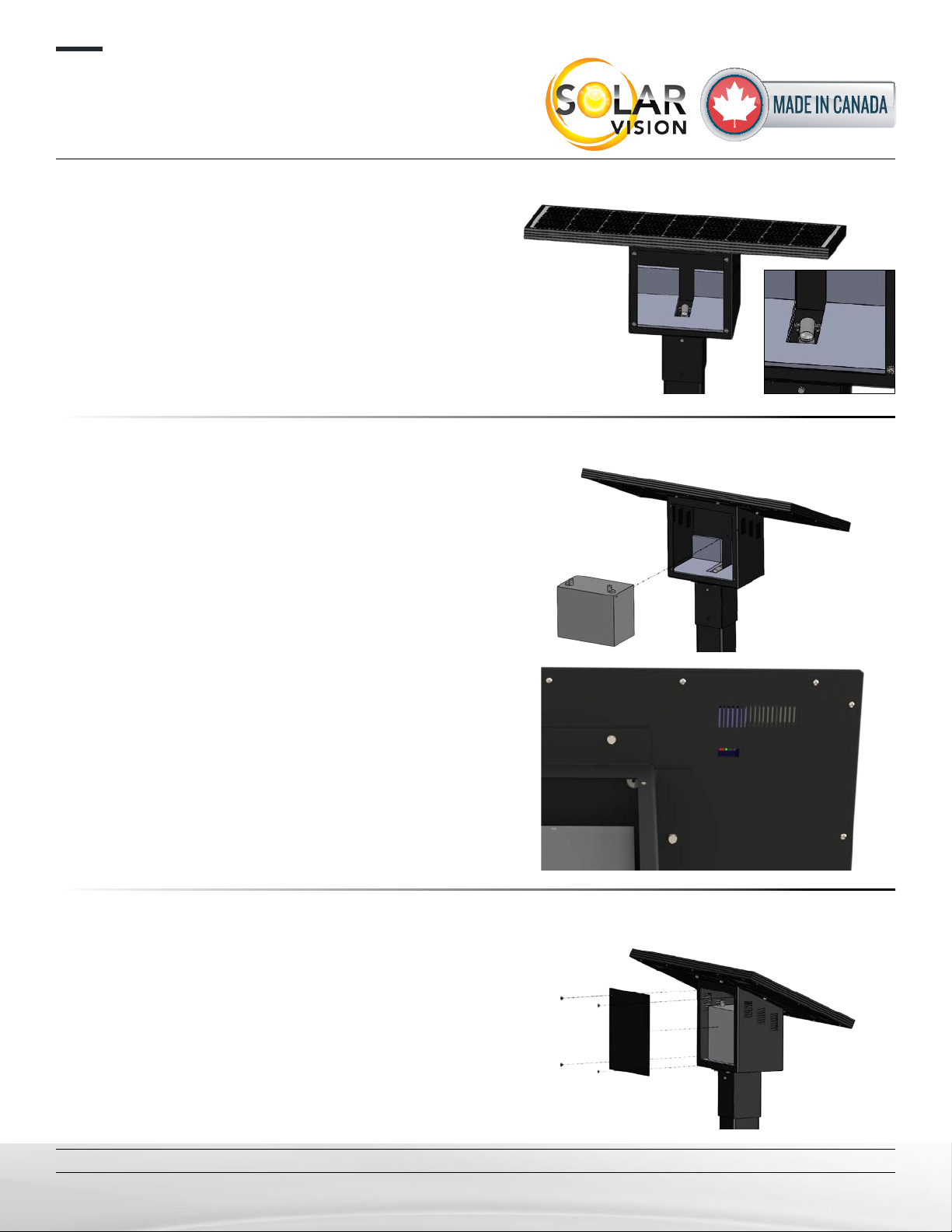
STEP 3:
Insert the luminaire power cable located in the battery
main enclosure through the 90 deg connector located
at the bottom to make it available for the luminaire con-
nection. Supplied cable: #16 AWG, 6ft cable length,
pre-installed on the control side.
Step 4:
Insert the battery inside the compartment and make
the connection using the quick connector labeled
“BATTERY”.
Conrm proper system operation by observing a green
indicator light behind the system status window.
Important note: Never wire the “External PV” cable
directly on the battery, this will cause irreversible
damage to the battery. The “External PV” cable is
used to add a solar module as needed.
STEP 5:
Close the quick access door.
P.3/10

installation ManUal
ZX60 & ZX100 commercial solar lighting system
Solar Vision inc. www.solar-vision.com inf[email protected] T. 1-819-729-0450
Revision 3.0
STEP 6:
Install the tenon and light at the desired location. Refer to the tenon drawing and luminaire installation
guide herein for more details.
Avoid having the luminaire illuminate the solar module surface. This would cause synchronization
errors as the articial lighting coming from the luminaire would simulate daylight causing the
luminaire to turn ON and OFF every 5 minutes.
The 12Vdc luminaire requires 3 connections: Red positive (+), Black negative (-) and White dim-
ming (signal). It is important to make all 3 connections so that the system operates correctly according
to current or future operating proles.
Solar Module
Orientation Period Autonomy
losses
South (≈ optimal)
Annual 0%
Summer 0%
Winter 0%
East / West
Annual -21%
Summer -15%
Winter -40%
North
Annual -50%
Summer -41%
Winter -72%
SOLAR PANNEL ORIENTATION
AND AUTONOMY
1.1 INSTALLATION GUIDELINES
To avoid a loss of autonomy and a malfunction:
• The luminaire must be installed horizontally and must never be tilted;
• The luminaire must be installed in an open space with no trees or
structures nearby, this could favour snow accumulation and shading;
• The solar module must ideally oriented towards the south, otherwise see
table “ORIENTATION AND AUTONOMY”.
Failing to follow these recommendations can result in loss of system per-
formance.
FACTORS AFFECTING AUTONOMY:
Lack of sunshine, very low ambient temperature, snow accumulation due
to trees or structures nearby, shading due to nearby trees or structures,
solar module orientation (see table), sunshine below the monthly aver-
ages.
1.2 STORAGE AND HANDLING:
If you wish to store the luminaire, the battery needs to be recharged before storing for a period of 15 days or more
in order to prevent damage to the battery. The luminaire must be stored at 20°C room temperature.
The luminaire should never be manipulated when the battery is inside. Use the quick access door to
remove the battery before handling.
1.3 DEEP DISCHARGE PROTECTION
This protection signicantly increases battery lifespan. This protection also prevents permanent damage to the
battery caused by very deep discharges during cold weather. When the battery reaches a 50% state of charge,
the battery is automatically disconnected from the system until it’s state of charge reaches 85% i.e. about
1 day of sunshine in summer and about 4 days of sunshine in winter.
1.4 DAY-NIGHT TRANSITION
The xture uses the solar panel to detect day and night periods. The night transition requires a very low bright-
ness level for 5 continuous minutes. This constraint prevents false night transitions. Avoid exposing the luminaire
to an articial light source that may cause synchronization errors by simulating the day. If the xture operates
erratically, make sure the solar module is not covered with debris or heavy snow. The luminaire automatically
corrects synchronization errors after 24 hours. The occupancy sensor has its own photocell, which does not
activate when the ambient brightness is too high.
P.4/10
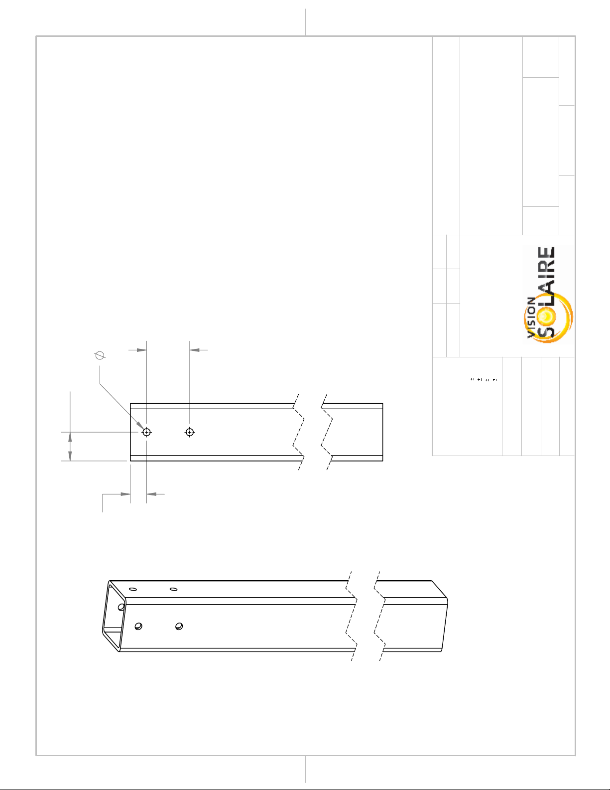
.50
2.00
1.13
3.00
NOTE:
The installation of the battery box
on the top of the lamp post
requires drilling the post as per
the presented drilling patturn.
The lamp will be secured using
one bolt going through the lamp
post.
Drill on the 4 faces to facilitate
the installation.
A A
B B
2
2
1
1
PROJECT:
WEIGHT:
"
THICKNESS
THE INFORMATION CONTAINED IN THIS
DRAWING IS THE SOLE PROPERTY OF
VISION SOLAIRE INC ANY
REPRODUCTION IN PART OR AS A WHOLE
WITHOUT THE WRITTEN PERMISSION OF
VISION SOLAIRE COM IS
PROHIBITED.
PROPRIETARY AND CONFIDENTIAL
DIMENSIONS ARE IN INCHES
DEFAULT TOLERANCES:
ANGULAR
1°
TWO PLACE DECIMAL
.06"
THREE PLACE DECIMAL
.031"
HOLES
.005"
MATERIAL
FINISH
DRAWN
DATE
NAME
ZX60
TITLE:
SIZE
A
DWG. NO.
REV
SCALE: 1:5
UNLESS OTHERWISE SPECIFIED:
JFOL 5 Jan 2021
SHEET 1 OF 1
ZX60-02
DO NOT SCALE DRAWING
4IN POST
DRILLING PATTERN
0
POLE NOT INCLUDED
Tenon drilling pattern not
shown here.
P.5/10

1.500
5.125
.45
2.50
NOTE:
The installation of the battery box
on the top of the lamp post
requires drilling the post as per
the presented drilling patturn.
The lamp will be secured using
one bolt going through the lamp
post.
Drill on the 4 faces to facilitate
the installation.
REV.
DESCRIPTION
DATE
PAR
1
MODIFICATION OF THE NOTE
5 JAN 2021
JFOL
A A
B B
2
2
1
1
PROJECT:
WEIGHT: 36.45
"
THICKNESS
THE INFORMATION CONTAINED IN THIS
DRAWING IS THE SOLE PROPERTY OF
VISION SOLAIRE INC ANY
REPRODUCTION IN PART OR AS A WHOLE
WITHOUT THE WRITTEN PERMISSION OF
VISION SOLAIRE COM IS
PROHIBITED.
PROPRIETARY AND CONFIDENTIAL
DIMENSIONS ARE IN INCHES
DEFAULT TOLERANCES:
ANGULAR
1°
TWO PLACE DECIMAL
.06"
THREE PLACE DECIMAL
.031"
HOLES
.005"
MATERIAL
FINISH
DRAWN
DATE
NAME
ZX100
TITLE:
SIZE
A
DWG. NO.
REV
SCALE: 1:5
UNLESS OTHERWISE SPECIFIED:
JFOL
30 sep 2020
SHEET 1 OF 1
ZX100-02
DO NOT SCALE DRAWING
5IN POST
DRILLING PATTERN
Material <not specified>
1
POLE NOT INCLUDED
Tenon drilling pattern not
shown here.
P.6/10
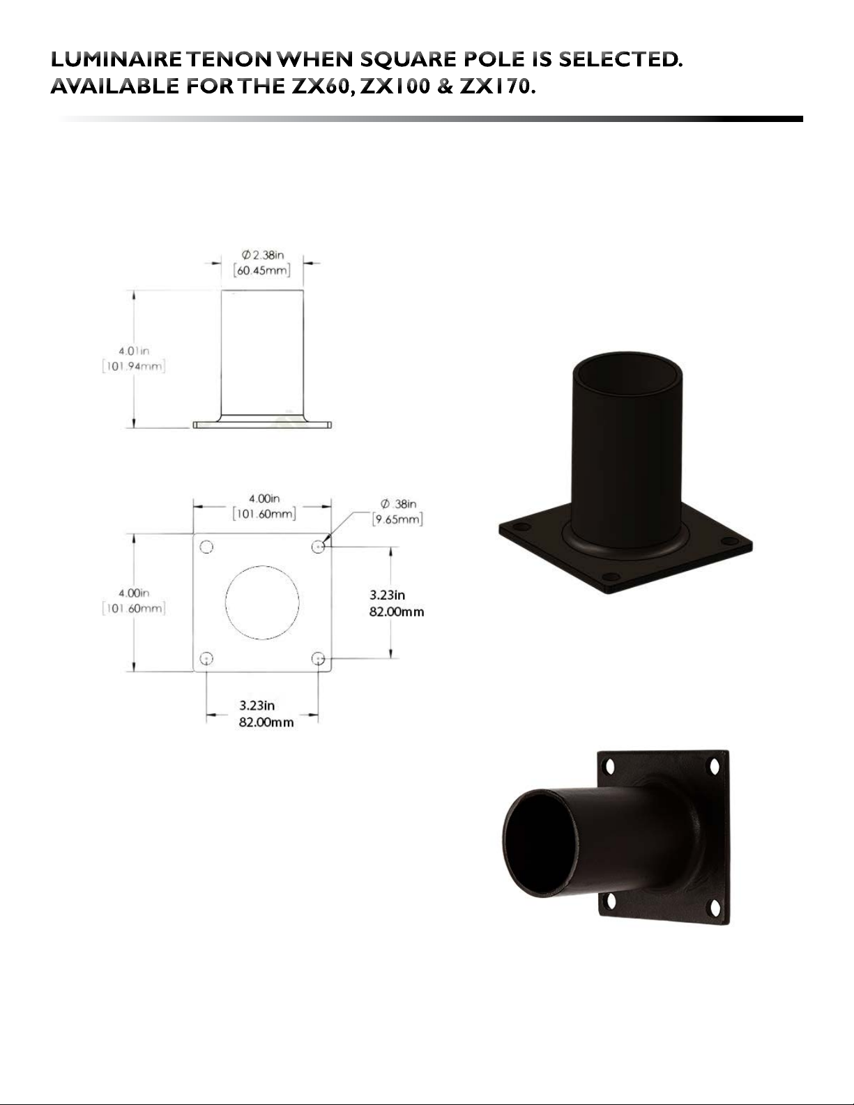
Hardware 1/4-20x1” (4x) included for installing the tenon. Please coordinate drilling holes with
your pole manufacturer.
P.7/10
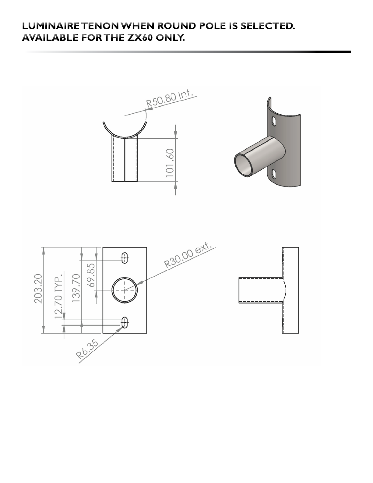
Hardware 5/16-18x1” (2x) included for installing the tenon. Please coordinate drilling holes
with your pole manufacturer.
P.8/10
SERIES-H
INSTALLATION INSTRUCTIONS
LED STREET LIGHTS
When using electrical equipment, basic safety precau�ons should always
be followed including the following:
IMPORTANT SAFEGUARDS
READ AND FOLLOW ALL SAFETY INSTRUCTIONS
1.
2.
3.
4.
5.
To avoid the possibility of electrical shock, turn offpower supply before
installa�on or servicing. Installa�on and servicing should be performed
by qualied personnel.
When closing cover of xture, be sure all wires are inside housing to
avoid pinching wires.
If Photo Receptacle is installed refer to “Photo Control” sec�on for
instruc�ons.
Product must be installed in accordance with your local electrical code.
If you are not familiar with these codes and requirements, consult a
qualied electrician.
Do not change the structure or any commponents of the xture to
ensure safety.
SAVE THIS INSTRUCTIONS FOR FUTURE REFERENCE
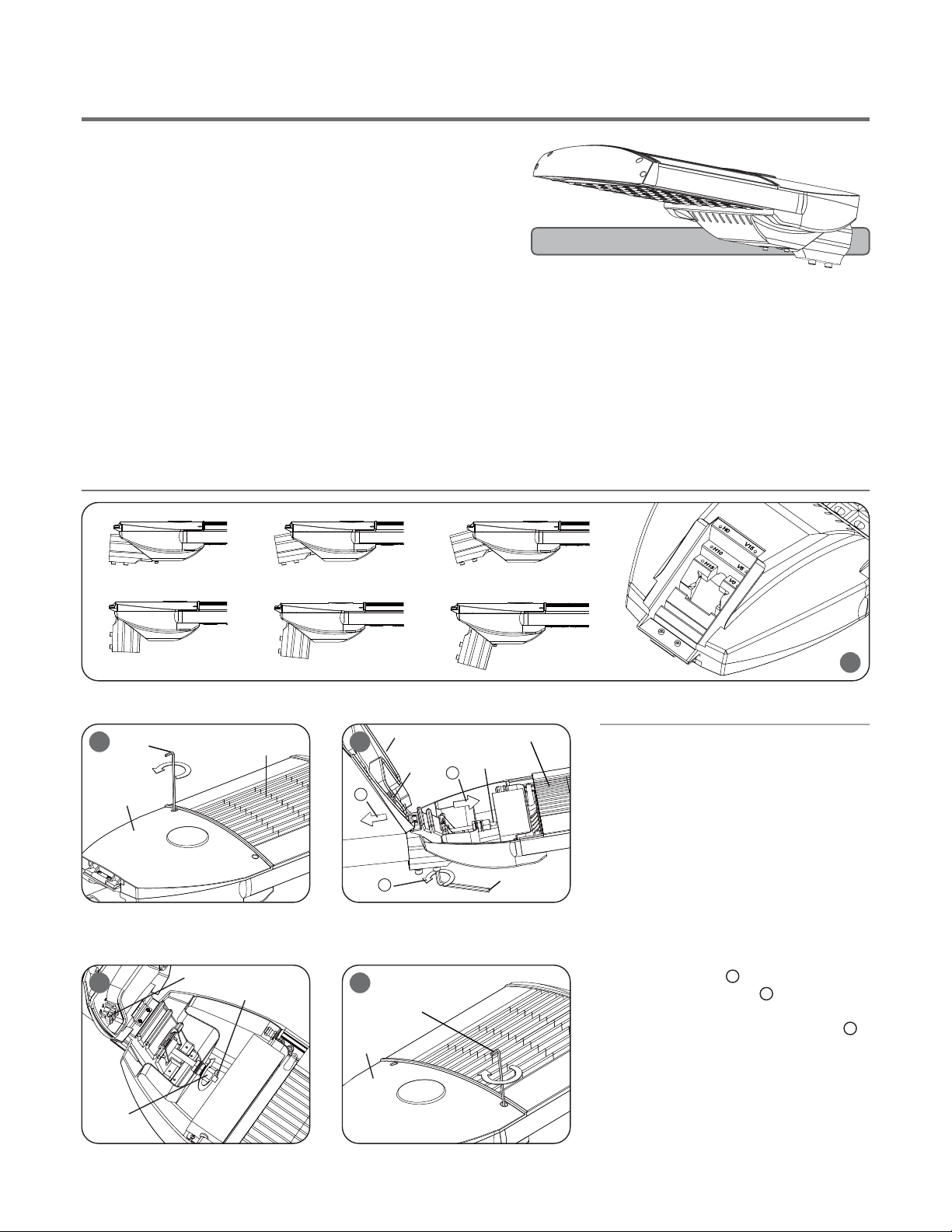
TO INSTALL:
STANDARD MOUNTING
1
H0 H10 H15
V0 V5 V15
Allen Wrench*¹
2Heatsink
Cover
*¹ Allen Wrench: 4mm (5/32”)
*¹ Inner Hexagon Screw: M5 (3/16”)
*² Allen Wrench: 6mm (7/32”)
*² Inner Hexagon Screw: M8 (5/16”)
A
B
C
Allen Wrench*²
Heatsink
Cover in Open Posi�on
Terminal
Block
LED Driver
Input Wires
Pole
3
Terminal Block
LED Driver
Input Wires
M16 (5/8”)
waterproof connector
4 5
Allen Wrench*¹
Cover
Adjust the mul-angle er (0, 5 ,15 degree
verƟcal and 0, 10, 15 degree horizontal) to
proper posion by 4mm (5/32”) allen wrench.
STEP 1:
To open cover, hold xture by heatsink with
the light modules facing down. Remove 2
screws on the cover by 4mm (5/32”) allen
wrench.
STEP 2:
Keep the cover in open posion, lead the
Input Wires in through the M16 (5/8”) water-
proof connector (see ), Do not ghten.
Slide xture onto pole (see )and adjust
to level posion. Once desired posion is
achieved, ghten (2) mounng bolts (see ).
A
B
C
STEP 3:
Connect the Input Wires into Terminal Block,
Reference “Electrical ConnecƟons” secon
for compleng electrical connecons.
STEP 4:
Close the cover, ghten (2) mounng bolts.
STEP 5:
REV1403ALHSL-1
*Max installaon height: 15M
*Pole er diameter: 60mm (2.4”) / *48mm diameter need longer screws
*This product must be grounding
P.9/10
IMPORTANT
DC(Direct Current) based system.
DC BASED
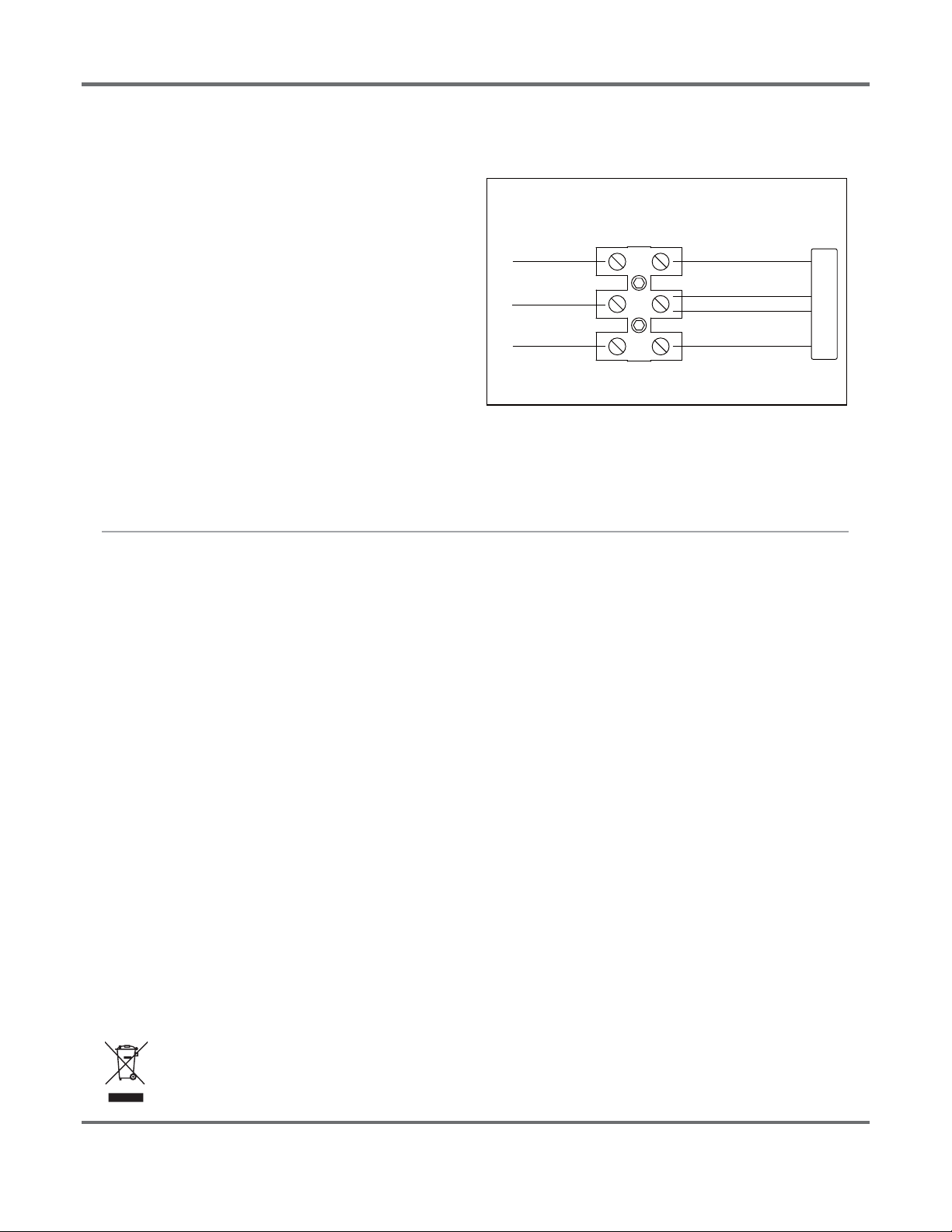
STEP 1:
Make the following Electrical ConnecƟons:
a.
b.
Connect INPUT POSITIVE(+) conductor to RED WIRE posiƟon
of the terminal block or POSITIVE(+) conductor of LED driver.
Connect INPUT NEGATIVE(-) conductor to BLACK WIRE
posiƟon of the terminal block or Vin NEGATIVE(-)/DIM (-)
conductor of LED driver.
Connect INPUT DIM SIGNAL (WHITE WIRE) to Dim (+) signal
wire (blue) of LED Driver.
STEP 2:
Make sure all excess input wires are pushed into pole, screws are
Ɵghtened.
STEP 3:
Close cover by rmly pushing cover towards xture, making sure
that no wires are pinched and Sealing gasket are fully engaged.
STEP 4:
If the xture without a terminal block, please insulate all electrical
connecƟons with wire nuts suitable for at least 90°C
TERMINAL BLOCK
LED DRIVER
NEGATIVE(-)
DIM(-) White
POSITIVE(+) Vin POSITIVE(+) RED
+
-
INPUT WIRING
FIXTURE WIRING
This marking indicates that this product should not be disposed with other household wastes throughout the EU.
To prevent possible harm to the environment or human health from uncontrolled waste disposal, recycle it
responsibly to promote the sustainable reuse of material resources. To return your used device, please use
the return and collecƟon systems or contact the retailer where the product was purchased. They can take
this product for environmental safe recycling.
DIM Signal
(white)
c.
DIM(+) Signal (Blue)
Vin NEGATIVE(-) BLACK
P.10/10
This manual suits for next models
1
Table of contents
Popular Inverter manuals by other brands


VOLTCRAFT
VOLTCRAFT PI 100-12 USB operating instructions

Magmaweld
Magmaweld Monotig 160i user manual

Hantek
Hantek 1025G user manual

Steca
Steca StecaGrid 2010+ Slave Installation and operating instructions

B.A. International
B.A. International SuPreme S5 operating instructions

Peak
Peak PKC0AX owner's manual