SOLAR VISION ZX Series User manual

installation ManUal
ZX series - commercial solar lighting systems
Solar Vision inc. www.solar-vision.ca info@solar-vision.ca T. 1-819-729-0450
Revision 3.3 | May 24, 2022
IMPORTANT: Always install the system assembly on the pole before inserting the batteries.
The assembly system should never be manipulated when the batteries are installed inside.
LIST OF MATERIAL
A) Solar module with integrated control system and wiring. (1 per system)
B) Battery main enclosure (1 per system)
C) Battery, 12V (1 per system)
D) Stainless Steel Hardware, 1/4”-20 (ZX60) or 5/16”-18 (ZX100 & ZX170) for system assembly
E) LED Luminaire (12Vdc compatible only)
F) Luminaire mounting tenon
Note : The ZX system operates at 12Vdc. Other voltage will damage system.
ZX SYSTEM COMPONENTS ZX FINAL ASSEMBLY
P.1/12

installation ManUal
ZX series - commercial solar lighting systems
Solar Vision inc. www.solar-vision.ca info@solar-vision.ca T. 1-819-729-0450
Revision 3.3 | May 24, 2022
STEP 1:
Using the supplied 1/4”-20 (ZX60) bolts or the 5/16”-18 (ZX100 & ZX170) bolts and hardware (hex bolt,
lock washer, at washer), fasten the battery compartment to the solar module as indicated on the im-
age. Orientation of the battery box is critical, use the “Door on this Side” sticker to conrm orientation.
Step 2: Find the optimal system orientation
a) First determine the system orientation so that the solar
module faces true south.
b) Use the drill guide at the end of the document to drill the
pole at the appropriate locations.
c) Install the system on the pole. Use the 1/4”-20 bolt and
hardware (bolts, at washer, lock washer and nut) through
the pole to secure in place.
P.2/12

installation ManUal
ZX series - commercial solar lighting systems
Solar Vision inc. www.solar-vision.ca info@solar-vision.ca T. 1-819-729-0450
Revision 3.3 | May 24, 2022
STEP 4:
Install the tenon and light at the desired location. Refer to the tenon drawing and luminaire installation
guide herein for more details.
Avoid having the luminaire illuminate the solar module surface. This would cause synchronization
errors as the articial lighting coming from the luminaire would simulate daylight causing the
luminaire to turn ON and OFF every 5 minutes.
The 12Vdc luminaire requires 3 connections: Red positive (+), Black negative (-) and White dim-
ming (signal). It is important to make all 3 connections so that the system operates correctly according
to current or future operating proles.
STEP 3:
Insert the luminaire power cable located in the battery
main enclosure through the 90 deg connector located
at the bottom to make it available for the luminaire con-
nection. Supplied cable: #16 AWG, pre-installed on the
control side, not shown in this drawing.
Step 5:
Insert the battery inside the compartment and make
the connection using the quick connector labeled
“BATTERY”.
Conrm proper system operation by observing a green
indicator light behind the system status window.
P.3/12

installation ManUal
ZX series - commercial solar lighting systems
Solar Vision inc. www.solar-vision.ca info@solar-vision.ca T. 1-819-729-0450
Revision 3.3 | May 24, 2022
Solar Module
Orientation Period Autonomy
losses
South (≈ optimal)
Annual 0%
Summer 0%
Winter 0%
East / West
Annual -21%
Summer -15%
Winter -40%
North
Annual -50%
Summer -41%
Winter -72%
SOLAR PANNEL ORIENTATION
AND AUTONOMY
STEP 5:
Close the quick access door.
1.1 INSTALLATION GUIDELINES
To avoid a loss of autonomy and a malfunction:
• The luminaire must be installed horizontally and must never be tilted;
• The luminaire must be installed in an open space with no trees or
structures nearby, this could favour snow accumulation and shading;
• The solar module must ideally oriented towards the south, otherwise see
table “ORIENTATION AND AUTONOMY”.
Failing to follow these recommendations can result in loss of system per-
formance.
FACTORS AFFECTING AUTONOMY:
Lack of sunshine, very low ambient temperature, snow accumulation due
to trees or structures nearby, shading due to nearby trees or structures,
solar module orientation (see table), sunshine below the monthly aver-
ages.
1.2 STORAGE AND HANDLING:
If you wish to store the luminaire, the battery needs to be recharged before storing for a period of 15 days or more
in order to prevent damage to the battery. The luminaire must be stored at 20°C room temperature.
The luminaire should never be manipulated when the battery is inside. Use the quick access door to
remove the battery before handling.
1.3 DEEP DISCHARGE PROTECTION
This protection signicantly increases battery lifespan. This protection also prevents permanent damage to the
battery caused by very deep discharges during cold weather. When the battery reaches a 50% state of charge,
the battery is automatically disconnected from the system until it’s state of charge reaches 85% i.e. about
1 day of sunshine in summer and about 4 days of sunshine in winter.
1.4 DAY-NIGHT TRANSITION
The xture uses the solar panel to detect day and night periods. The night transition requires a very low bright-
ness level for 5 continuous minutes. This constraint prevents false night transitions. Avoid exposing the luminaire
to an articial light source that may cause synchronization errors by simulating the day. If the xture operates
erratically, make sure the solar module is not covered with debris or heavy snow. The luminaire automatically
corrects synchronization errors after 24 hours. The occupancy sensor has its own photocell, which does not
activate when the ambient brightness is too high.
P.4/12

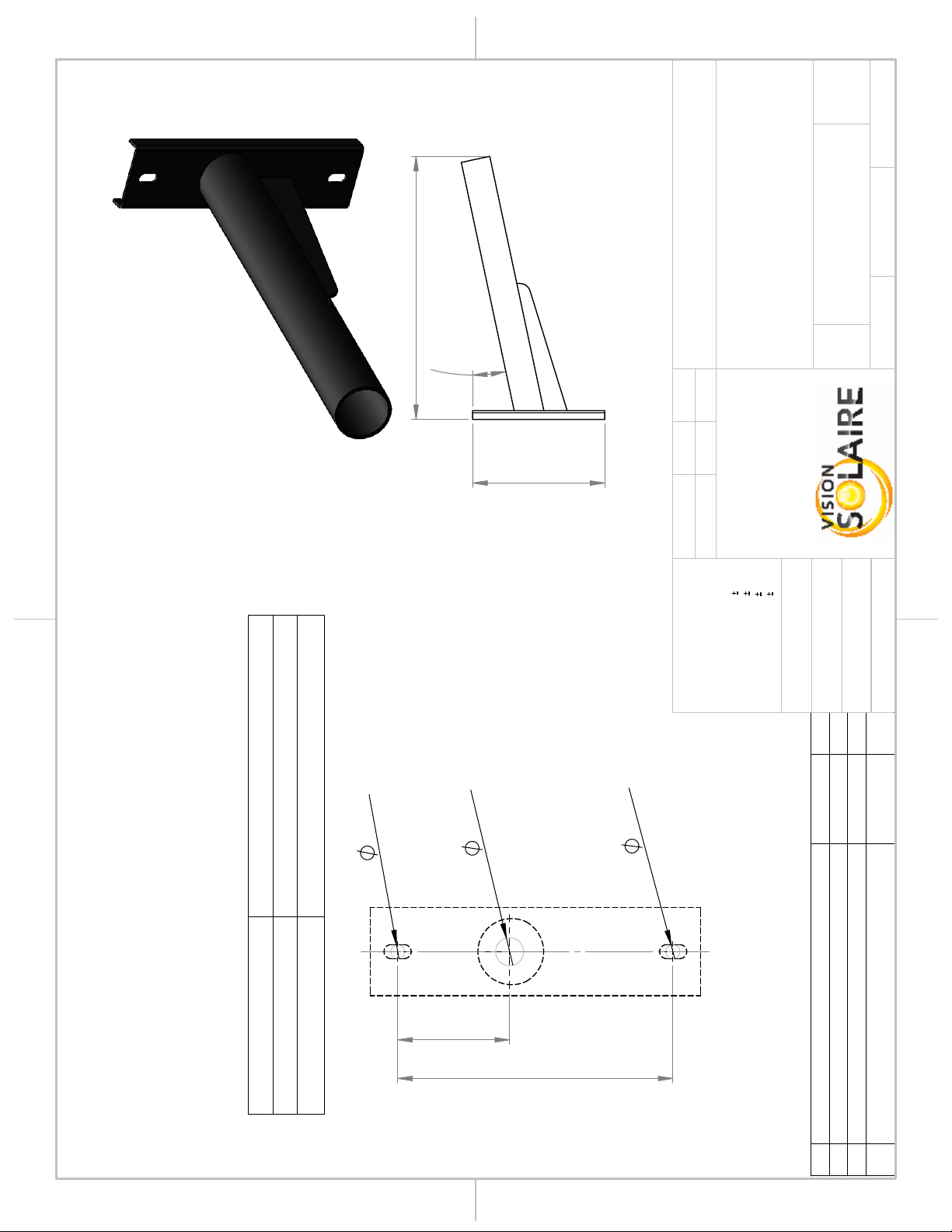
.50
2.00
1.125
3.00
NOTE:
The installation of the solar system
must be made using a bolt which
passes through the post. Follow the
this drilling pattern for the position of
holes.
Drill holes on the 4 faces to facilitate
the installation.
Tenon drilling schemes not shown
here. See on next pages.
The fixture's tenon must be installed
a minimum of 12" below the top of
the post.
REV.
DESCRIPTION
DATE
FROM
1
ADDTION OF THE ROUND POST AND
MODIFICATION OF THE NOTE
20 JUL 2021
JFOL
A A
B B
2
2
1
1
PROJECT:
WEIGHT:
"
THICKNESS
THE INFORMATION CONTAINED IN THIS
DRAWING IS THE SOLE PROPERTY OF
VISION SOLAIRE INC ANY
REPRODUCTION IN PART OR AS A WHOLE
WITHOUT THE WRITTEN PERMISSION OF
VISION SOLAIRE COM IS
PROHIBITED.
PROPRIETARY AND CONFIDENTIAL
DIMENSIONS ARE IN INCHES
DEFAULT TOLERANCES:
ANGULAR
1°
TWO PLACE DECIMAL
.06"
THREE PLACE DECIMAL
.031"
HOLES
.005"
MATERIAL
FINISH
DRAWN
DATE
NAME
ZX60
TITLE:
SIZE
A
DWG. NO.
REV
SCALE: 1:5
UNLESS OTHERWISE SPECIFIED:
JFOL 5 Jan 2021
SHEET 1 OF 1
ZX60-02
DO NOT SCALE DRAWING
DRILLING PATTERN
SOLAR SYSTEM
4IN POST
1
POLE NOT INCLUDED
Tenon drilling pattern not
shown here.
P.5/12

1.500
5.125
.45
2.50
NOTE:
The installation of the solar system
must be made using a bolt which
passes through the post. Follow the
this drilling pattern for the position of
holes.
Drill holes on the 4 faces to facilitate
the installation.
Tenon drilling schemes not shown
here. See on next pages.
The fixture's tenon must be installed
a minimum of 12" below the top of
the post.
REV.
DESCRIPTION
DATE
PAR
3
MODIFICATION OF THE NOTE
20 JUL 2021
JFOL
2
REFERENCE TO ZX170
12 JUL 2021
JFOL
1
MODIFICATION OF THE NOTE
5 JAN 2021
JFOL
A A
B B
2
2
1
1
PROJECT:
WEIGHT: 36.45
"
THICKNESS
THE INFORMATION CONTAINED IN THIS
DRAWING IS THE SOLE PROPERTY OF
VISION SOLAIRE INC ANY
REPRODUCTION IN PART OR AS A WHOLE
WITHOUT THE WRITTEN PERMISSION OF
VISION SOLAIRE COM IS
PROHIBITED.
PROPRIETARY AND CONFIDENTIAL
DIMENSIONS ARE IN INCHES
DEFAULT TOLERANCES:
ANGULAR
1°
TWO PLACE DECIMAL
.06"
THREE PLACE DECIMAL
.031"
HOLES
.005"
MATERIAL
FINISH
DRAWN
DATE
NAME
ZX100 & ZX170
TITLE:
SIZE
A
DWG. NO.
REV
SCALE: 1:5
UNLESS OTHERWISE SPECIFIED:
JFOL
30 sep 2020
SHEET 1 OF 1
ZX100-02
DO NOT SCALE DRAWING
DRILLING PATTERN
SOLAR SYSTEM
5IN POST
Material <not specified>
3
POLE NOT INCLUDED
Tenon drilling pattern not
shown here.
P.6/12

3.20
3.20
1.60
1.60
1.60
1.60
0.359" TYP.X4
1.00"
PROVIDED BY DEFAULT FOR THE ZX & TX SERIES WHEN NO OTHER OPTIONAL
POLE ARM IS PURCHASED
HARDWARE 1/4-20X1" (4X) INCLUDED FOR INSTALLING THE TENON
PLEASE COORDINATE DRILLING HOLES WITH YOUR POLE MANUFACTURER.
THE FIXTURE'S TENON MUST BE INSTALLED AT A MINIMUM DISTANCE BELOW
BELOW THE TOP OF THE POST AS PER THE FOLLOWING TABLE:
PERCEMENTS
DIMENSIONS IN INCHES
REV.
DESCRIPTION
DATE
PAR
1 MOUNTING LOCATION
25 MAI 2022
JFOL
0
ORIGINAL
2 AOUT 2021
JFOL
DISTANCE MIN.
MODÈLE
12" (305mm)
ZX30 & ZX60
18" (457mm)
ZX100, ZX170, TX150 & TX300
A A
B B
2
2
1
1
PROJECT:
WEIGHT:
"
THICKNESS
THE INFORMATION CONTAINED IN THIS
DRAWING IS THE SOLE PROPERTY OF
VISION SOLAIRE INC ANY
REPRODUCTION IN PART OR AS A WHOLE
WITHOUT THE WRITTEN PERMISSION OF
VISION SOLAIRE COM IS
PROHIBITED.
PROPRIETARY AND CONFIDENTIAL
DIMENSIONS ARE IN INCHES
DEFAULT TOLERANCES:
ANGULAR
1°
TWO PLACE DECIMAL
.06"
THREE PLACE DECIMAL
.031"
HOLES
.005"
MATERIAL
FINISH
DRAWN
DATE
NAME
ZX - TX
TITLE:
SIZE
A
DWG. NO.
REV
SCALE: 1:2
UNLESS OTHERWISE SPECIFIED:
JFOL
2 AUG 2021
SHEET 1 OF 1
TENSQ45
DO NOT SCALE DRAWING
DRILLING PATTERN
HORIZONTAL TENON FOR
4" & 5" SQUARE POLE
PAINTED STEEL
1
P.7/12

0.422"
1.00"
0.422"
3.00 3.00
AVAILABLE FOR THE ZX30 & ZX60 ONLY.
PROVIDED BY DEFAULT FOR ROUND POLE WHEN NO OTHER OPTIONAL
POLE ARM IS PURCHASED.
HARDWARE 5/16-18X1" (X2) INCLUDED FOR INSTALLING THE TENON.
PLEASE COORDINATE DRILLING HOLES WITH YOUR POLE MANUFACTURER.
THE FIXTURE'S TENON MUST BE INSTALLED AT A MINIMUM DISTANCE BELOW
THE TOP OF THE POST AS PER THE FOLLOWING TABLE:
DRILLING PATTERN
DIMENSIONS IN INCHES
REV.
DESCRIPTION
DATE
PAR
1 MOUNTING LOCATION
25 MAI 2022
JFOL
0
ORIGINAL
2 AUG 2021
JFOL
DISTANCE MIN.
MODEL
12" (305mm)
ZX30 & ZX60
A A
B B
2
2
1
1
PROJECT:
WEIGHT:
"
THICKNESS
THE INFORMATION CONTAINED IN THIS
DRAWING IS THE SOLE PROPERTY OF
VISION SOLAIRE INC ANY
REPRODUCTION IN PART OR AS A WHOLE
WITHOUT THE WRITTEN PERMISSION OF
VISION SOLAIRE COM IS
PROHIBITED.
PROPRIETARY AND CONFIDENTIAL
DIMENSIONS ARE IN INCHES
DEFAULT TOLERANCES:
ANGULAR
1°
TWO PLACE DECIMAL
.06"
THREE PLACE DECIMAL
.031"
HOLES
.005"
MATERIAL
FINISH
DRAWN
DATE
NAME
ZX
TITLE:
SIZE
A
DWG. NO.
REV
SCALE: 1:2
UNLESS OTHERWISE SPECIFIED:
JFOL
2 AUG 2021
SHEET 1 OF 1
TENRD4
DO NOT SCALE DRAWING
DRILLING PATTERN
HORIZONTAL TENON FOR
4" ROUND POLE
PAINTED STEEL
1
P.8/12

Power Modules Dimension Weight
EPA
C
P.9/12
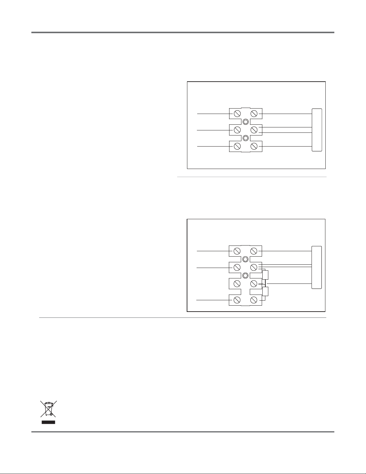
IMPORTANT
DC(Direct Current) based system.
3 POSITIONS TERMINAL BLOCK
TERMINAL BLOCK 3 POSITIONS
a.
b.
Connect INPUT POSITIVE(+) conductor to RED WIRE posiƟon
of the terminal block or POSITIVE(+) conductor of LED driver.
Connect INPUT NEGATIVE(-) conductor to BLACK WIRE
posiƟon of the terminal block or Vin NEGATIVE(-)/DIM (-)
conductor of LED driver.
Connect INPUT DIM SIGNAL (WHITE WIRE) to Dim (+) signal
wire (blue) of LED Driver (0-10V).
STEP 3:
Make sure all excess input wires are pushed into pole, screws are
Ɵghtened.
STEP 4:
Close cover by rmly pushing cover towards xture, making sure
that no wires are pinched and Sealing gasket are fully engaged.
STEP 5:
If the xture is without a terminal block, please insulate all
electrical connecƟons with wire nuts suitable for at least 90°C
TERMINAL BLOCK
LED DRIVER
NEGATIVE(-)
DIM(-) White
POSITIVE(+) Vin POSITIVE(+) RED
+
-
INPUT WIRING
FIXTURE WIRING
This marking indicates that this product should not be disposed with other household wastes throughout the EU.
To prevent possible harm to the environment or human health from uncontrolled waste disposal, recycle it
responsibly to promote the sustainable reuse of material resources. To return your used device, please use
the return and collecƟon systems or contact the retailer where the product was purchased. They can take
this product for environmental safe recycling.
DIM Signal
(white)
c.
DIM(+) Signal (Blue)
Vin NEGATIVE(-) BLACK
STEP 1 / Étape 1:
Determine if you have a terminal block with 3 or 4 positions :
Déterminer si vous avez un terminal block à 3 ou 4 positions :
STEP 2 / Étape 2:
Make the following Electrical ConnecƟons :
Effectuer les raccordements électriques suivants :
*Without voltage divider resistors*
TERMINAL BLOCK
LED DRIVER
NEGATIVE(-)
DIM(-) White
POSITIVE(+) Vin POSITIVE(+) RED
+
-
INPUT WIRING
FIXTURE WIRING
DIM Signal
(white)
DIM(+) Signal (Blue)
Vin NEGATIVE(-) BLACK
4 POSITIONS TERMINAL BLOCK
TERMINAL BLOCK 4 POSITIONS
*With voltage divider resistors for base Dim % settings*
* Avec diviseur de tension pour réglage du % de gradation de base.
-
(black)
(black)
(red)
NO Connect
R1
R2
Pre-wired on driver side
Pre-wired on driver side
P.10/12

9.00
1.00
0.69
0.69
4.25
11.50
9.00
1.00
4.13
0.69
0.69
DRILLING PATTERN
OPTIONAL ELLIPTICAL POLE ARM #RE2MA AVAILABLE FOR THE ZX & TX SERIES.
HARDWARE 5/8-11X 3" (X2) INCLUDED FOR INSTALLING THE POLE ARM.
PLEASE COORDINATE DRILLING HOLES WITH YOUR POLE MANUFACTURER.
THE FIXTURES'S POLE ARM MUST BE INSTALLED AT A MINIMUM DISTANCE BELOW
THE TOP OF THE POST AS PER THE FOLLOWING TABLE:
DIMENSIONS IN INCHES
BACK
L = 24"
H = 12"
A = 2.5" x 3.375"
DIAM. EXT. = 2.375"
THICKNESS = 0.125"
REV.
DESCRIPTION
DATE
PAR
0
ORIGINAL
26 MAI 2022
JFOL
DISTANCE MIN.
MODEL
18" (457mm)
ZX100, ZX170, TX150 & TX300
A A
B B
2
2
1
1
PROJECT:
WEIGHT:
0.125"
THICKNESS
THE INFORMATION CONTAINED IN THIS
DRAWING IS THE SOLE PROPERTY OF
VISION SOLAIRE INC ANY
REPRODUCTION IN PART OR AS A WHOLE
WITHOUT THE WRITTEN PERMISSION OF
VISION SOLAIRE COM IS
PROHIBITED.
PROPRIETARY AND CONFIDENTIAL
DIMENSIONS ARE IN INCHES
DEFAULT TOLERANCES:
ANGULAR
1°
TWO PLACE DECIMAL
.06"
THREE PLACE DECIMAL
.031"
HOLES
.005"
MATERIAL
FINISH
BLACK
DRAWN
DATE
NAME
ZX - TX
TITLE:
SIZE
A
DWG. NO.
REV
SCALE: 1:25
UNLESS OTHERWISE SPECIFIED:
JFOL
26 MAI 2022
SHEET 2 OF 2
RE2MA
DO NOT SCALE DRAWING
DRILLING PATTERN
ELLIPTICAL POLE
ARM 2'
6063-T6 ALU.
0
P.11/12
9.85
4.00
0.50
1.00
0.50
11.81
12°
23.50
OPTIONAL STRAIGHT POLE ARM AVAILABLE FOR THE ZX & TX SERIES
HARDWARE 3/8"-16X 1-3/4" (2X) INCLUDED FOR INSTALLING THE POLE ARM.
PLEASE COORDINATE DRILLING HOLES WITH YOUR POLE MANUFACTURER.
THE FIXTURE'S POLE ARM MUST BE INSTALLED AT A MINIMUM DISTANCE BELOW
THE TOP OF THE POST AS PER THE FOLLOWING TABLE:
DRILLING PATTERN
DIMENSIONS IN INCHES
DISTANCE MIN.
MODEL
12" (305mm)
ZX30 & ZX60
18" (457mm)
ZX100, ZX170, TX150 & TX300
REV.
DESCRIPTION
DATE
PAR
2 MOUNTING LOCATION
25 MAY 2022
JFOL
1
DIMENSIONS UPDATE
4 MAY 2022
JFOL
0
ORIGINAL
2 FEV 2022
JFOL
A A
B B
2
2
1
1
PROJECT:
WEIGHT:
"
THICKNESS
THE INFORMATION CONTAINED IN THIS
DRAWING IS THE SOLE PROPERTY OF
VISION SOLAIRE INC ANY
REPRODUCTION IN PART OR AS A WHOLE
WITHOUT THE WRITTEN PERMISSION OF
VISION SOLAIRE COM IS
PROHIBITED.
PROPRIETARY AND CONFIDENTIAL
DIMENSIONS ARE IN INCHES
DEFAULT TOLERANCES:
ANGULAR
1°
TWO PLACE DECIMAL
.06"
THREE PLACE DECIMAL
.031"
HOLES
.005"
MATERIAL
FINISH
DRAWN
DATE
NAME
ZX - TX
TITLE:
SIZE
A
DWG. NO.
REV
SCALE: 1:2
UNLESS OTHERWISE SPECIFIED:
JFOL
2 FEV 2022
SHEET 1 OF 1
RD212
DO NOT SCALE DRAWING
DRILLING PATTERN 2 FT
ARM @ 12DEG
FOR 4" & 5" POLE
PAINTED STEEL
2
P.12/12
This manual suits for next models
6
Table of contents
Other SOLAR VISION Lighting Equipment manuals


Popular Lighting Equipment manuals by other brands

EFFILUX
EFFILUX EFFI-FLEX-LG user manual

Satco
Satco NUVO 67-132 Installation and safety instructions

Cooper
Cooper AP2SQLED30 installation instructions

Viking Stage Lighting
Viking Stage Lighting VK760 user manual

JB-Lighting
JB-Lighting Varyscan 4 1200HMI user manual

One Lux
One Lux Omni-LED FLEXI Installation & operating instructions


