Ketra LS0 User manual

LS0
LOW-VOLTAGE LINEAR
Instlltion Guide
Models
CMLS0 (Coming in Phase 2)
HWLS0

Contents
Product Overview 3
Included Components 4
Pre-Installation 5
Installation 8
Determine Product Location 8
Install Mounting Brackets 9
Connect Linears 10
Connect to Controller 11
Configure Device using the Device Software 11
Example System Connection 12
Troubleshooting 12
Warranty Tech Support 13
FCC/IC Information
For FCC/IC information, please visit: www.lutron.com/fcc-ic
2|LS0 INSTALLATION GUIDE
P/N 3662707 Rev A
© 2022 Lutron Electronics Co., Inc. All rights reserved.

Product Overview
SPECIFICATIONS
UNIFORM LENS
(Coming in Phase 2)
HIGH OUTPUT LONG RUN
Width x Height 0.65 × 1.00 in
(16.5 × 25.4 mm)
0.65 × 0.65 in
(16.5 × 16.5 mm)
0.65 × 0.65 in
(16.5 × 16.5 mm)
Lumen Output 250 lm/ft 350 lm/ft 200 lm/ft
Delivered Output
(Light Transmission)
Coming in Phase 2 59 lm/W 59 lm/W
Power Consumption Coming in Phase 2 5.91 W/ft 3.38 W/ft
Maximum Run Length
per X96 Controller
15 ft (4.6 m) 15 ft (4.6 m) 24 ft (7.3 m)
Input Current 0.259 A/ft 0.259 A/ft 0.161 A/ft
Input Voltage 21 V-21 V-21 V-
Flexible Connector input and
Straight Connector output
* Available in custom ordering option
Flexible Connector input and
Flexible Connector output
* Available in custom ordering option
Straight Connector input and
Straight Connector output
* Available in custom and standard
ordering options
Straight Connector input and
Flexible Connector output
* Available in custom ordering option
6 in
(152.4 mm)
3|LS0 INSTALLATION GUIDE
P/N 3662707 Rev A
© 2022 Lutron Electronics Co., Inc. All rights reserved.

Included Components
LS0 Linear Segment
Adapter Type A, Mounting Clip & Screw
Adapter Type B, Mounting Clip & Screw
Screws & Mounting Bracket
Right Angle End Covers
Other System Components (ordered separately):
X96 Ketra Controller
(HWX96-XJ1)
4-wire cable ex. QSHCBLPM500
4|LS0 INSTALLATION GUIDE
P/N 3662707 Rev A
© 2022 Lutron Electronics Co., Inc. All rights reserved.

Pre-Installation
Install in accordance with all national and local electrical codes.
• Turn power OFF at circuit breker or remove fuse. Dmge to this product cused by wiring with power on
voids the wrrnty.
• Suitable for damp locations.
• Read all installation instructions and warnings before beginning installation process.
• Installation instructions may change without notice due to continuous improvements.
• Do not use product if it is damaged.
• Luminaires contain no user-serviceable parts.
• Do not connect product to any voltage or frequency supply other than an X96 controller.
• If placed in enclosure alongside other electrical components, take necessary precautions regarding
operating temperatures.
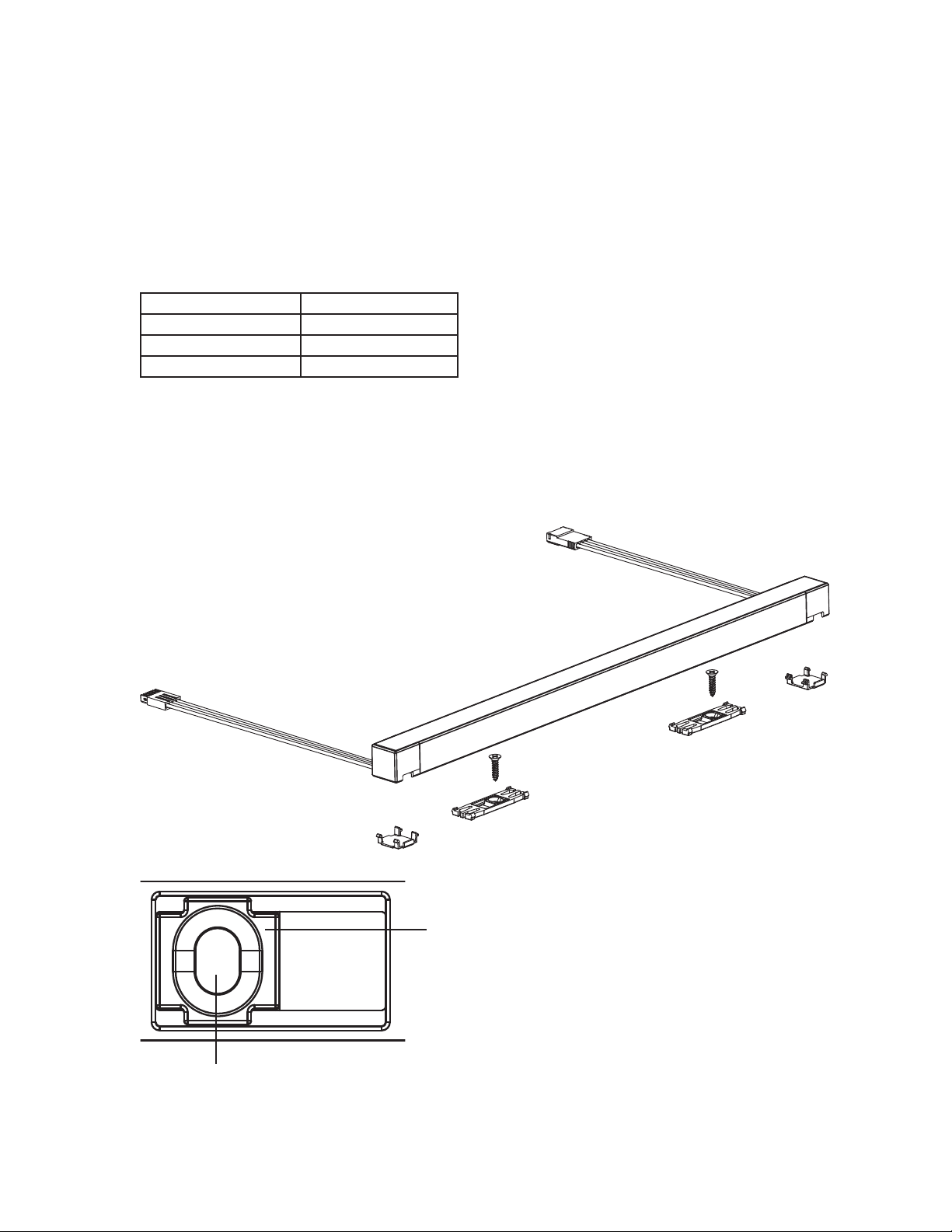
• Product is UL surface-mount listed and does not require a dedicated enclosure. Product can be recess-
mounted in an 11/16 in (17.5 mm) slot.
Note: For recessed applications there needs to be distance from the end of the LS0 and physical barriers due
to thermal expansion. The distance should be 1/32 in (0.8 mm) per foot for high output or 1/64 in (0.4 mm) per
foot for long run and uniform lens.
• Suitable for installation in the storage area of a clothes closet.
Notes:
-The X96 Ketra controller provides low-voltage power and communication to the LS0 luminaires. The X96
needs to be between the AC mains power source and the run of LS0 linear.
-Mount such that the total cable length from the X96 controller to the last LS0 segment is no more than
50 ft (15.2 m). A total cable length of 50 ft (15.2 m) can be used in a system run.
-Each X96 controller can support up to 15 ft (4.6 m) to 24 ft (7.3 m), depending on the style.
15 ft (4.6 m) for the high output style and 24 ft (7.3 m) for the long run style. For longer run lengths, use
additional X96 controllers.
-Connect all product in a single run to the X96 controller. For more details, please refer to the installation
instructions for the X96 controller.
-‘Star’ or parallel wiring installations are not supported (see diagrams on the following page).
5|LS0 INSTALLATION GUIDE
P/N 3662707 Rev A
© 2022 Lutron Electronics Co., Inc. All rights reserved.

PRE-INSTALLATION
Star or parallel wiring
installations are not supported
120277 V~60 Hz
Mains Supply
DO NOT WIRE IN PARALLEL
alimentation
120277 V~
60 Hz
Mains Supply
6|LS0 INSTALLATION GUIDE
P/N 3662707 Rev A
© 2022 Lutron Electronics Co., Inc. All rights reserved.

PRE-INSTALLATION
Notes:
-Products are connected end-to-end via the integrated connectors at each end of the product.
Note that there is an “input” and “output” connector on each product and orientation is critical.
A common mistake is installing the products backwards.
A typical run installation includes:
• X96 controller
• 4-conductor cable (16 AWG [1.5 mm2]) (ex. QSHCBLPM500)
• 10 in to 15 ft (254 mm to 4.6 m) or 24 ft (7.3 m) LS0 linear luminaires
• Adapters
• Right angle covers
• Mounting brackets
Input Input
Input
Input
Output Output
Output Output
7|LS0 INSTALLATION GUIDE
P/N 3662707 Rev A
© 2022 Lutron Electronics Co., Inc. All rights reserved.

Installation
STEP 1
Determine Product Location
1. Identify the location of each LS0 luminaire. Each segment box in a run will be labeled and numbered in the
order of the run layout. i.e., Segment #1 of 3, Segment #2 of 3, Segment #3 of 3 in a run with 3 segments.
2. Each LS0 segment must be setback from any walls by at least the minimum setback distance (2 in [50.8 mm]
for high output and long run, 0.25 in [6.35 mm] for uniform lens). Each segment must also have the appropriate
mixing depth for its lens type (4 in [101.6 mm] for high output and long run, 0.25 in [6.35 mm] for uniform lens)
as shown in the figure below.
3. Locate wiring holes for LS0 luminaire.
4. Determine location for X96 controller. Measure the length from the controller to the first luminaire and cut your
4-conductor cable to length. Since this a low-voltage wire, conduits are not required. The total cable length
from the X96 controller to the last LS0 segment may not exceed 50 ft (15.2 m), not including the length of the
luminaires. For example, 30 ft (9.1 m) of cable can be run from the X96 controller to the first 8 ft (2.4 m) segment.
Then 15 ft (4.6 m) of cable can be run to the next 7 ft (2.1 m) segment. Total cable length, NOT including the
luminaire, would be 45 ft (13.7 m) which is under the acceptable length of 50 ft (15.2 m). Total cable length,
including the luminaire, would be 60 ft (18.2 m).
5. Ensure that there are enough adapters to complete your wiring. The X96 controller comes with one adapter
(Adapter Type A on page 4) to connect to the first LS0 segment. Extra adapters must be purchased separately
or as an Adapter Type AAdapter Type B pair (UNLS0-ADPT1).
Note: Adapter pairs are required when 4-conductor cable is used between any individual segments.
Lens will be evenly
illuminated when
viewed directly
Lens will have visible
hot spots when
viewed directly.
Uniform Lens
(Coming in Phase 2)
High Output &
Long Run 0.25 in (6.35 mm)
Mixing Depth &
Setback Distance
2 in (50.8 mm) Setback
Distance (symmetric)
4 in (101.6 mm)
Mixing Depth
8|LS0 INSTALLATION GUIDE
P/N 3662707 Rev A
© 2022 Lutron Electronics Co., Inc. All rights reserved.

STEP 2
Install Mounting Brackets
1. LS0 segments attach to the mounting brackets on the underside of the luminaire. Determine location of
mounting brackets based on the center line of the segments keeping them centered along the length of the
luminaire with spacing no more than 2 ft (0.6 m) apart.
Luminaire Length Required Brackets
4 ft (1.2 m) or less 2
4.1 ft (1.2 m) 6 ft (1.8 m) 3
6.1 ft (1.8 m) - 8 ft (2.4 m) 4
Note: Extra brackets are provided and can be used at the discretion of the installer.
2. Mount brackets to the surface with screws.
3. When screwing mounting brackets to the surface, do not over tighten the screws. The bracket should be snug
to the surface but the center block should be able to rotate and slide up and down within the vertical slot.
INSTALLATION
Note: After mounting, confirm that the bracket is free to slide left and right (approx. 3 in (76.2 mm) overall).
Center block
Vertical Slot
9|LS0 INSTALLATION GUIDE
P/N 3662707 Rev A
© 2022 Lutron Electronics Co., Inc. All rights reserved.

INSTALLATION
STEP 3
Connect Linears
1. Before mounting a linear with flexible connectors, determine the direction for the flexible connector and use
one of the right angled end covers to hold the wires in place. Omit the cover if flexible connector is threaded
through the mounting surface.
2. Snap products into mounting brackets such that input end of first luminaire is nearest to the controller. If it is
dicult to align the brackets to the product, make sure the bracket screw is not so tight that it cannot rotate or
slide up and down within the vertical slot.
3. Connect linears to each other.
4. Use cable and adapters where appropriate. Use adapters when connecting from a segment to a cable.
5. When connecting to the adapters, use the wiring identification to feed-through the signals appropriately.
6. If the standard design was purchased with straight connectors, adapters will always be used to make right
angle connections as shown in Figure A. If the custom ordering option with flexible connectors was purchased,
the flexible connectors from the linear segments will plug directly into each other as shown in Figure B.
Position 4
Black | COM
Position 3
Purple | DATA+
Position 1
Red | V+
Position 2
White | DATA-
Position 1
Red | V+
Position 2
White | DATA-
Position 4
Black | COM
Position 3
Purple | DATA+
Figure A Figure B
1/5 in
(5 mm)
Strip Length:
10|LS0 INSTALLATION GUIDE
P/N 3662707 Rev A
© 2022 Lutron Electronics Co., Inc. All rights reserved.

STEP 4
Connect to Controller
See the X96 install guide on how to install the X96 controller.
1. Connect your 4-conductor cable to the Type A adapter. Ensure you are following the wiring rules to avoid mis-wiring.
When connecting to the adapters, use the wiring identification to feed-through the signals appropriately.
2. At the first luminaire, connect the input connector to the Type A adapter.
3. At the controller, wire the other end of your 4-conductor cable to the controller connector using the wiring
identification below.
4. Review your wiring before turning on the power.
5. Apply power to the X96 controller.
STEP 5
Configure Device using the Design Software
1. This step will be completed by a trained Lutron-certified technician or engineer.
STEP 3
Connect Linears (continued)
7. If connecting an adapter to a flexible connector, utilize the mounting clip by screwing it to the mounting
surface and sliding the adapter onto it in the following orientation.
8. Ensure that connectors are completely engaged.
Do not install in a way that puts any pulling force on the cables and connections.
INSTALLATION
Position 3
Purple | DATA+
Position 4
Black | COM
Position 2
White | DATA-
Position 1
Red | V+
Wire Input
Side
11|LS0 INSTALLATION GUIDE
P/N 3662707 Rev A
© 2022 Lutron Electronics Co., Inc. All rights reserved.

Troubleshooting
Ketra’s LS0 linear should power on to a default white state. If it powers on to some other color, that means there’s a
problem in the installation conditions. See the table below for the meaning of each color.
TROUBLESHOOTING TABLE
Color Condition Correction
Red or OFF Voltage from X96 Controller is
too low
Ensure that the controller is the Ketra X96
controller. Check to see if total cable length
exceeds 50 ft (15 m), reduce to 50 ft (15 m) of
cable from X96 to last LS0 segment. Ensure that
power conductors are 16 AWG (1.5 mm2) wires, or
use the QSHCBL(P)-M500. Ensure that length
of LS0 linear does not exceed maximum length
requirements i.e., 15 ft (4.6 m) for high output and
24 ft (7.3 m) for long run. Verify power connections
(V+ and COM on page 10) are wired correctly on
the X96 controller and each luminaire adapter
Magenta LS0 is installed backwards Disconnect power, check wiring at adapters and
follow wiring directions in the LS0 and X96 Install
Guides, or disconnect luminaire and reverse the
direction
Blue Missing or reversed
communication signals
Verify communication (DATA+ and DATA- on
page 10) are wired correctly on the X96 controller
and each luminaire adapter
Green or OFF Line voltage is too low Line voltage must be nominally 120 or 277 V~
60 Hz for X96
Yellow Number of luminaires exceeds
length limits. Limit for 15 ft
(4.6 m) for high output and
diused lens type and 24 ft
(7.3 m) for long run lens type.
Remove excess luminaires and power cycle the X96
controller
Example System Connection
12|LS0 INSTALLATION GUIDE
P/N 3662707 Rev A
© 2022 Lutron Electronics Co., Inc. All rights reserved.

Warranty Tech Support
Limited warranty terms can be found at:
www.ketra.com/warranty
For questions and technical support, please contact:
(844) 588-6445
ketrasupport@lutron.com
Ketra is a trademark or registered trademark of Lutron Electronics Co., Inc. in the US and/or other countries.
13|LS0 INSTALLATION GUIDE
P/N 3662707 Rev A
© 2022 Lutron Electronics Co., Inc. All rights reserved.

LS0
LINÉAIRE BASSE TENSION
Guide d’instlltion
Modèles
CMLS0 (à venir dans la phase 2)
HWLS0

Contenu
Présentation du produit 3
Composants inclus 4
Pré-installation 5
Installation 8
Déterminer l’emplacement du produit 8
Installer les supports de montage 9
Connecter les linéaires 10
Connexion au contrôleur 11
Configurer l’appareil à l’aide du logiciel de conception 11
Exemple de connexion d’un système 12
Dépannage 12
Garantie et Assistance technique 13
Informations FCC/ IC
Pour les Informations de la FCC/IC, veuillez consulter : www.lutron.com/fcc-ic
2|LS0 GUIDE D’INSTALLATION
N° de pièce 3662707 Rév A
© 2022 Lutron Electronics Co., Inc. Tous droits réservés.

Présentation du produit
SPÉCIFICATIONS
LENTILLE UNIFORME
(à venir dans la phase 2)
HAUT
RENDEMENT
LONG
CÂBLAGE
Largeur x Hauteur 16,5 x 25,4 mm
(0,65 × 1,00 po)
16,5 × 16,5 mm
(0,65 × 0,65 po)
16,5 × 16,5 mm
(0,65 × 0,65 po)
Rendement lumineux 250 lm/pi 350 lm/pi 200 lm/pi
Rendement mesuré
(Transmission de la
lumière)
Á venir dans la phase 2 59 lm/W 59 lm/W
Consommation
électrique
Á venir dans la phase 2 5,91 W/pi 3,38 W/pi
Longueur maximum de
câble par contrôleur
X96
4,6 m (15pi) 4,6 m (15pi) 7,3 m (24pi)
Courant d’entrée 0,259 A/pi 0,259 A/pi 0,161 A/pi
Tension d’alimentation 21 V-21 V-21 V-
Entrée à connecteur flexible et
sortie à connecteur droit
* Disponible en option de commande
personnalisée
Entrée à connecteur flexible et
sortie à connecteur flexible
* Disponible en option de commande
personnalisée
Entrée à connecteur droit et
sortie à connecteur droit
* Disponible en options de commande
personnalisées et standard
Entrée à connecteur droit et
sortie à connecteur flexible
* Disponible en option de commande
personnalisée
3|LS0 GUIDE D’INSTALLATION
N° de pièce 3662707 Rév A
© 2022 Lutron Electronics Co., Inc. Tous droits réservés.

Composants inclus
Segment linéaire LS0
Vis et support de montage
Couvercles d’extrémité à angle droit
Autres composants du système
(vendus séparément):
Contrôleur Ketra X96
(HWX96-XJ1)
Câble à 4 fils, par ex. QSHCBLPM500
Adaptateur de type A, clip de montage et vis
Adaptateur de type B, clip de montage et vis
4|LS0 GUIDE D’INSTALLATION
N° de pièce 3662707 Rév A
© 2022 Lutron Electronics Co., Inc. Tous droits réservés.

Pré-installation
Eectuez l’installation en conformité avec les codes électriques en vigueur.
• Coupez l’alimentation au niveau du disjoncteur ou enlevez le fusible. Les dommages causés à ce produit par un
câblage sous tension annulent la garantie.
• Convient aux endroits humides.
• Lisez toutes les instructions d’installation et les avertissements avant de commencer le processus d’installation.
• Les instructions d’installation peuvent changer sans préavis en raison d’améliorations continues.
• N’utilisez pas ce produit s’il est endommagé.
• Les luminaires ne contiennent aucune pièce réparable par l’utilisateur.
• Ne connectez pas le produit à une alimentation (tension ou fréquence) autre qu’un contrôleur X96.
• S’il est placé dans un boîtier à côté d’autres composants électriques, prenez les précautions nécessaires
concernant les températures de fonctionnement.
• Le produit est homologué UL pour être monté en surface. Ne nécessite pas de boîtier dédié. Le produit peut
être encastré dans une fente de 17,5 mm (11/16 po).
Remarque: Pour les applications encastrées, il doit y avoir une distance entre l’extrémité du LS0 et les barrières
physiques, du fait de la dilatation thermique. La distance doit être de 0,8mm tous les 30,5cm (1/32po par pied)
pour les luminaires à haut rendement ou de 0,4 mm tous les 30,5cm (1/64po par pied) pour les longs câblages
et une lentille uniforme.
• Peut être installé dans l'espace de stockage d'un placard à vêtements.
Remarques:
-Le contrôleur Ketra X96 fournit une alimentation basse tension et la communication aux luminaires LS0.
Le X96 doit être installé entre la source d’alimentation secteur et l’ensemble linéaire LS0.
-Montez-le de façon à ce que la longueur totale du câble entre le contrôleur X96 et le dernier segment LS0
ne dépasse pas 15,2m (50pi). La longueur totale de câble utilisable dans un système est de 15,2m (50pi).
-Chaque contrôleur X96 peut prendre en charge entre 4,6m (15pi) et 7,3m (24pi) de câble, selon le style.
4,6m (15pi) pour le type à haut rendement et 7,3m (24pi) pour le type à long câblage. Pour des longueurs
plus importantes, utilisez des contrôleurs X96 supplémentaires.
-Connectez tous les produits en série au contrôleur X96. Pour plus de détails, veuillez vous référer aux
instructions d’installation du contrôleur X96.
-Les installations de câblage en «étoile» ou en parallèle ne sont pas prises en charge (consultez les
schémas à la page suivante).
5|LS0 GUIDE D’INSTALLATION
N° de pièce 3662707 Rév A
© 2022 Lutron Electronics Co., Inc. Tous droits réservés.

PRÉ-INSTALLATION
Les installations de câblage
en étoile ou en parallèle ne
sont pas prises en charge NE PAS CÂBLIER EN PARALLÈLE
alimentation
120277 V~
60 Hz
Alimentation
secteur
120277 V~
60 Hz
Alimentation
secteur
6|LS0 GUIDE D’INSTALLATION
N° de pièce 3662707 Rév A
© 2022 Lutron Electronics Co., Inc. Tous droits réservés.

PRÉ-INSTALLATION
Remarques:
-Les produits sont connectés bout à bout via les connecteurs intégrés à chaque extrémité du produit. Notez
qu’il existe un connecteur «entrée» et «sortie» sur chaque produit et que l’orientation est cruciale. Une
erreur commune consiste à installer les produits à l’envers.
Une installation typique comprend:
• Contrôleur X96
• Câble à 4conducteurs (1,5 mm2[16 AWG]) (ex. QSHCBLPM500)
• Luminaires linéaires LSO de 254mm à 4,6m (10po à 15pi) ou de 7,3m (24pi)
• Adaptateurs
• Couvercles à angle droit
• Supports de montage
Entrée Entrée
Entrée
Entrée
Sortie Sortie
Sortie Sortie
7|LS0 GUIDE D’INSTALLATION
N° de pièce 3662707 Rév A
© 2022 Lutron Electronics Co., Inc. Tous droits réservés.
Other manuals for LS0
1
Table of contents
Languages:
Other Ketra Lighting Equipment manuals