SOLAR VISION TX360 User manual

installation ManUal
tx360 & tx180 commercial solar lighting system
Solar Vision inc. www.solar-vision.ca info@solar-vision.ca T. 1-819-729-0450
Revision 4.0 | May 25, 2023
IMPORTANT: Always install the system assembly on the pole before inserting the batteries.
The assembly system should never be handled when the batteries are installed inside.
LIST OF MATERIAL BY MODEL
TX180 SYSTEM: TX360 SYSTEM:
Battery/Control main enclosure Battery/Control main enclosure
Battery, 12V (1 per system) Battery, 12V (2 per system, in series)
L shape prole, 30in long (2 per system) L shape prole, 30in long (2 per system)
L shape prole, 26in long (2 per system) L shape prole, 53in long (2 per system)
Solar Module 180W (1 per system) Solar Module 180W (2 per system)
3/8” stainless steel hardware for assembly 3/8” 5/16 stainless steel hardware for assembly
5/16” stainless steel hardware for solar module
assembly
5/16” stainless steel hardware for solar module
assembly
LED luminaire, 12Vdc compatible, with tenon LED luminaire, 24Vdc compatible, with tenon
Note 1: The TX180 system is a 12Vdc system with one (1) 12V battery and one (1) 180W solar module. This system is
compatible with an LED luminaire operating at 12Vdc only.
Note 2: The TX360 system is a 24Vdc system with two (2) 12V batteries in series and two (2) 180W solar modules. This
system is compatible with an LED luminaire operating at 24Vdc. Do not use a 12Vdc luminaire on a 24Vdc system.
This will cause permanent damage to the LED driver.
TX180 System Components TX360 System Components
*Elliptical tube mounting arm and luminaire NOT shown *Elliptical tube mounting arm and luminaire NOT shown
P.1/11
installation ManUal
tx360 & tx180 commercial solar lighting system
Solar Vision inc. www.solar-vision.ca info@solar-vision.ca T. 1-819-729-0450
Solar Vision inc. www.solar-vision.ca inf[email protected] T. 1-819-729-0450
Revision 4.0 | May 25, 2023
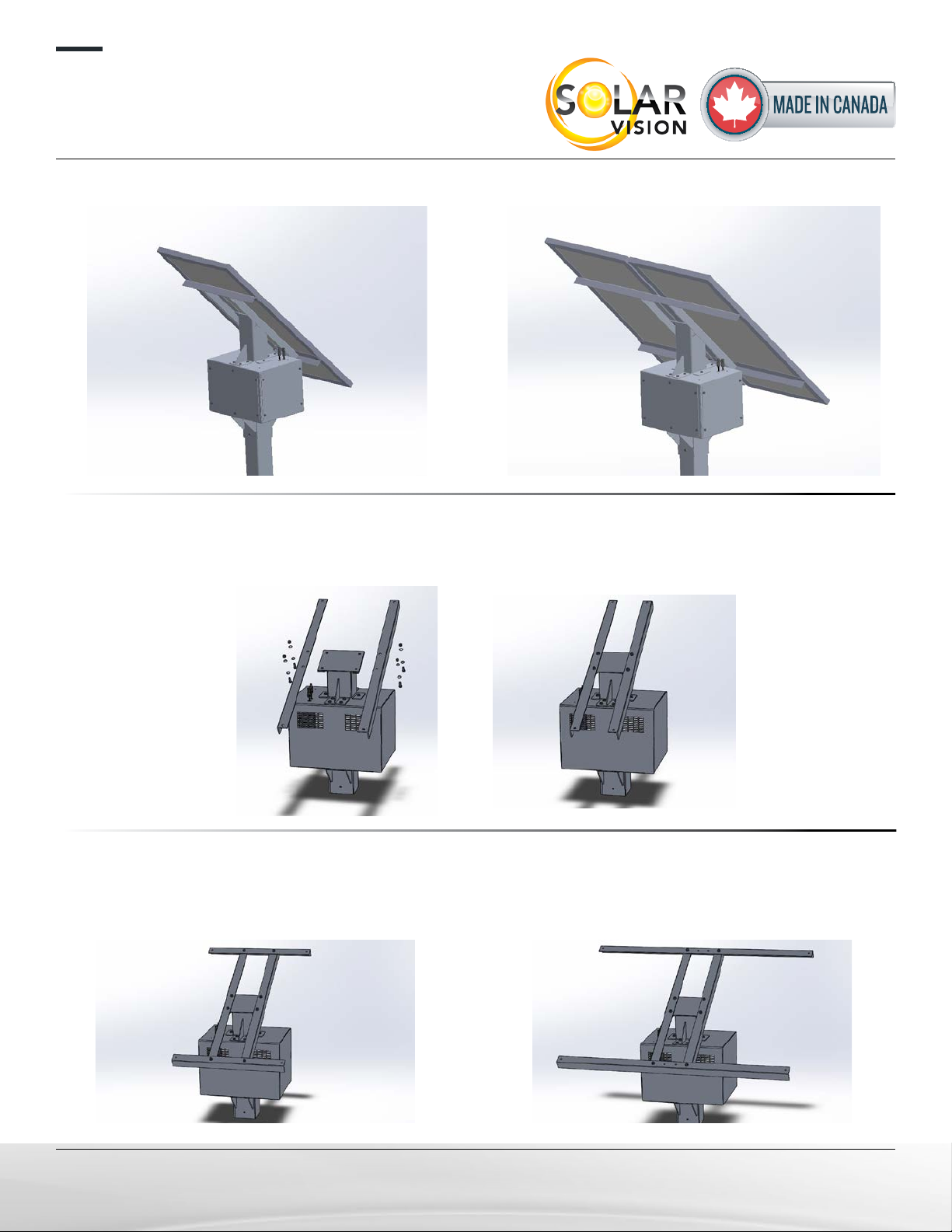
STEP 1:
Using the 3/8-16 x 1¼” bolts and hardware (hex bolt, at washer, lock washer and hex nut), tighten the
two 30in “L” channels to the “main support” as indicated on the image.
STEP 2:
Using the 3/8-16 x 1” bolts and hardware (hex bolt, at washer, lock washer and hex nut), tighten the
two “L” channels (26in or 53in according to model) to the “30in L channel” as indicated on the image.
TX180 FINAL ASSEMBLY TX360 FINAL ASSEMBLY
This step is identical
for the TX180 & TX360
TX360
TX180
P.2/11
installation ManUal
tx360 & tx180 commercial solar lighting system
Solar Vision inc. www.solar-vision.ca info@solar-vision.ca T. 1-819-729-0450
Solar Vision inc. www.solar-vision.ca inf[email protected] T. 1-819-729-0450
Revision 4.0 | May 25, 2023
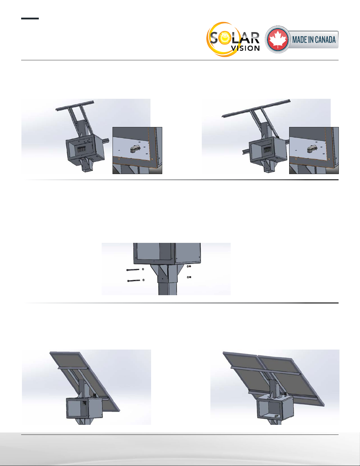
STEP 3:
Pass through the luminaire power cable (preinstalled in the battery box) into the 90 degree connector
to make it available for the luminaire connection. 10FT, #16 AWG is pre-wired.
STEP 4:
1. Determine the system’s orientation so that the solar panels are facing South.
2. Once the orientation is determined, use the drilling guide at the end of the document to drill holes
at the proper location.
3. Slide the system on the pole and use the 3/8”-16 x 6½” bolts and hardware to secure the system
into position. Bolts crosses the pole.
STEP 5:
Using the 5/16-18 x 1” bolts and hardware (hex bolt, at washer, lock washer and hex nut), install the
solar panels using their precut frame holes.
Note: The solar panel junction boxe needs to be on the down side.
TX180 TX360
TX180 TX360
P.3/11
installation ManUal
tx360 & tx180 commercial solar lighting system
Solar Vision inc. www.solar-vision.ca info@solar-vision.ca T. 1-819-729-0450
Solar Vision inc. www.solar-vision.ca inf[email protected] T. 1-819-729-0450
Revision 4.0 | May 25, 2023
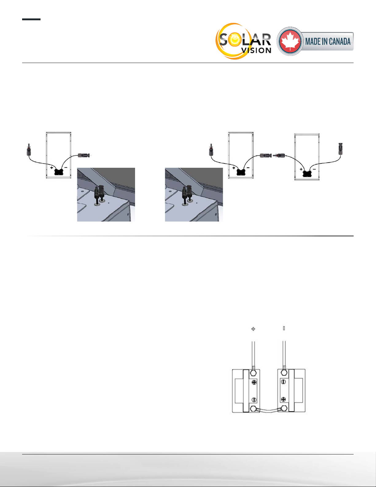
STEP 6:
1. For the TX360 only, make a serial connection between the solar panels, as shown in the picture
(The positive cable of one panel with the negative cable of the other panel).
2. Then connect the two remaining cables to the MC4 (pre-wired) connector on the main battery com-
partment as shown on the image.
STEP 7:
1. Following the + and - (positive and negative) orientation as indicated in the battery compartment,
insert the batteries.
2. For the TX300 only, using the supplied cable, make a serial connection between the batteries
(The positive terminal of one battery with the negative terminal of the other battery).
3. Then, by respecting the cable polarities, complete the batteries connection by using the pre wired
cables in the battery compartment.
TX180 TX360
TX360
ONLY
P.4/11
installation ManUal
tx360 & tx180 commercial solar lighting system
Solar Vision inc. www.solar-vision.ca inf[email protected] T. 1-819-729-0450
Revision 4.0 | May 25, 2023
STEP 8:
Close the battery compartment door using the 1/4”-20 bolts
and neopren washers.
STEP 9:
Install the pole arm and the luminaire at the desired location,
minimum 18in underneath the battery compartment.
Hardware not provided for the pole arm.
Pole arm and luminaire specications are included herein.
The DC lighting xture has 3 wires:
Positive Red(+), Negative Black(-), and Dimming White
(signal). Please make all 3 connections for proper opera-
tion.
DAY-NIGHT TRANSITION
The TX360 solar system uses the solar panel to detect day and night periods. The night transition re-
quires a very low brightness level for 5 continuous minutes. This constraint prevents false night transi-
tions that could be caused by storm clouds in the evening. If the solar module is covered with debris,
the solar module voltage may be too low and may cause light synchronization errors. If the light works
erratically, make sure the solar module is clean. The light automatically corrects synchronization errors
whithin 24 hours.
IMPORTANT
If you wish to store the batteries, they need to be recharged before storing for a period of 15 days or
more in order to prevent damage to the battery. The batteries must be stored at 20°C room temperature.
The light must be installed in an open area, no trees or nearby structure, this could favor snow accu-
mulation and shading.
Never manipulate the battery compartment when the batteries are inside. Use the quick access door to
remove the batteries before handling. Failing to follow these recommendations can result in seri-
ous danger and dammage.
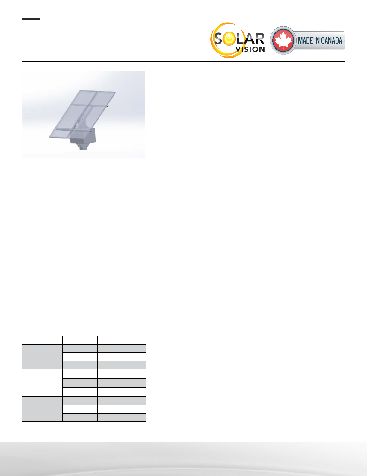
Orientation Period Autonomy losses
South (≈ optimal)
Annual 0%
Summer 0%
Winter 0%
East / West
Annual -21%
Summer -15%
Winter -40%
North
Annual -50%
Summer -41%
Winter -72%
SOLAR PANNEL ORIENTATION AND AUTONOMY
P.5/11

.50 x8
5.50
2.50
4.00
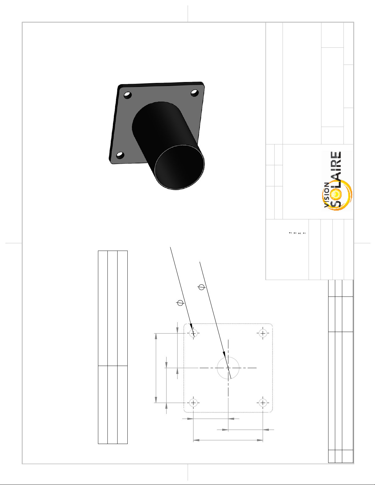
NOTE:
The installation of
the lamp on the
top of the post
requires drilling the
post as per the
presented drilling
pattern. The lamp
will be secured
using two bolts
through the lamp
post.
REV.
DESCRIPTION
DATE
PAR
5
DISTANCE BETWEEN MOUNTING HOLES
3 AVR 2023
JFOL
4
DRAWING PER MODEL
15 SEP 2022
JFOL
3
SIMPLIFICATION OF THE DRILLING PATTERN
27 JUN 2022
JFOL
2
HOLE SIZE AND POSITION ADJUSTED
13 OCT 2020
JFOL
1
UPDATE OF THE NOTE
26 MAR 2020
JFOL
A A
B B
2
2
1
1
PROJECT:
WEIGHT: 44.52
"
THICKNESS
THE INFORMATION CONTAINED IN THIS
DRAWING IS THE SOLE PROPERTY OF
VISION SOLAIRE INC ANY
REPRODUCTION IN PART OR AS A WHOLE
WITHOUT THE WRITTEN PERMISSION OF
VISION SOLAIRE COM IS
PROHIBITED.
PROPRIETARY AND CONFIDENTIAL
DIMENSIONS ARE IN INCHES
DEFAULT TOLERANCES:
ANGULAR
1°
TWO PLACE DECIMAL
.06"
THREE PLACE DECIMAL
.031"
HOLES
.005"
MATERIAL
FINISH
DRAWN
DATE
NAME
VS
TITLE:
SIZE
A
DWG. NO.
REV
SCALE: 1:5
UNLESS OTHERWISE SPECIFIED:
JFOL
26 MAR 2020
SHEET 1 OF 1
H55S_DRL_TX
DO NOT SCALE DRAWING
5IN POST
DRILLING PATTERN FOR
TX
5
POLE NOT INCLUDED
Tenon drilling pattern not
shown here.
P.6/11
P.7/11
3.20
3.20
1.60
1.60
1.60
1.60
0.359" TYP.X4
1.00"
PROVIDED BY DEFAULT FOR THE ZX & TX SERIES WHEN NO OTHER OPTIONAL
POLE ARM IS PURCHASED
HARDWARE 1/4-20X1" (4X) INCLUDED FOR INSTALLING THE TENON
PLEASE COORDINATE DRILLING HOLES WITH YOUR POLE MANUFACTURER.
THE FIXTURE'S TENON MUST BE INSTALLED AT A MINIMUM DISTANCE BELOW
BELOW THE TOP OF THE POST AS PER THE FOLLOWING TABLE:
PERCEMENTS
DIMENSIONS IN INCHES
REV.
DESCRIPTION
DATE
PAR
1 MOUNTING LOCATION
25 MAI 2022
JFOL
0
ORIGINAL
2 AOUT 2021
JFOL
DISTANCE MIN.
MODÈLE
12" (305mm)
ZX30 & ZX60
18" (457mm)
ZX100, ZX170, TX150 & TX300
A A
B B
2
2
1
1
PROJECT:
WEIGHT:
"
THICKNESS
THE INFORMATION CONTAINED IN THIS
DRAWING IS THE SOLE PROPERTY OF
VISION SOLAIRE INC ANY
REPRODUCTION IN PART OR AS A WHOLE
WITHOUT THE WRITTEN PERMISSION OF
VISION SOLAIRE COM IS
PROHIBITED.
PROPRIETARY AND CONFIDENTIAL
DIMENSIONS ARE IN INCHES
DEFAULT TOLERANCES:
ANGULAR
1°
TWO PLACE DECIMAL
.06"
THREE PLACE DECIMAL
.031"
HOLES
.005"
MATERIAL
FINISH
DRAWN
DATE
NAME
ZX - TX
TITLE:
SIZE
A
DWG. NO.
REV
SCALE: 1:2
UNLESS OTHERWISE SPECIFIED:
JFOL
2 AUG 2021
SHEET 1 OF 1
TENSQ45
DO NOT SCALE DRAWING
DRILLING PATTERN
HORIZONTAL TENON FOR
4" & 5" SQUARE POLE
PAINTED STEEL
1
Power Modules Dimension Weight
EPA
C
P.8/11

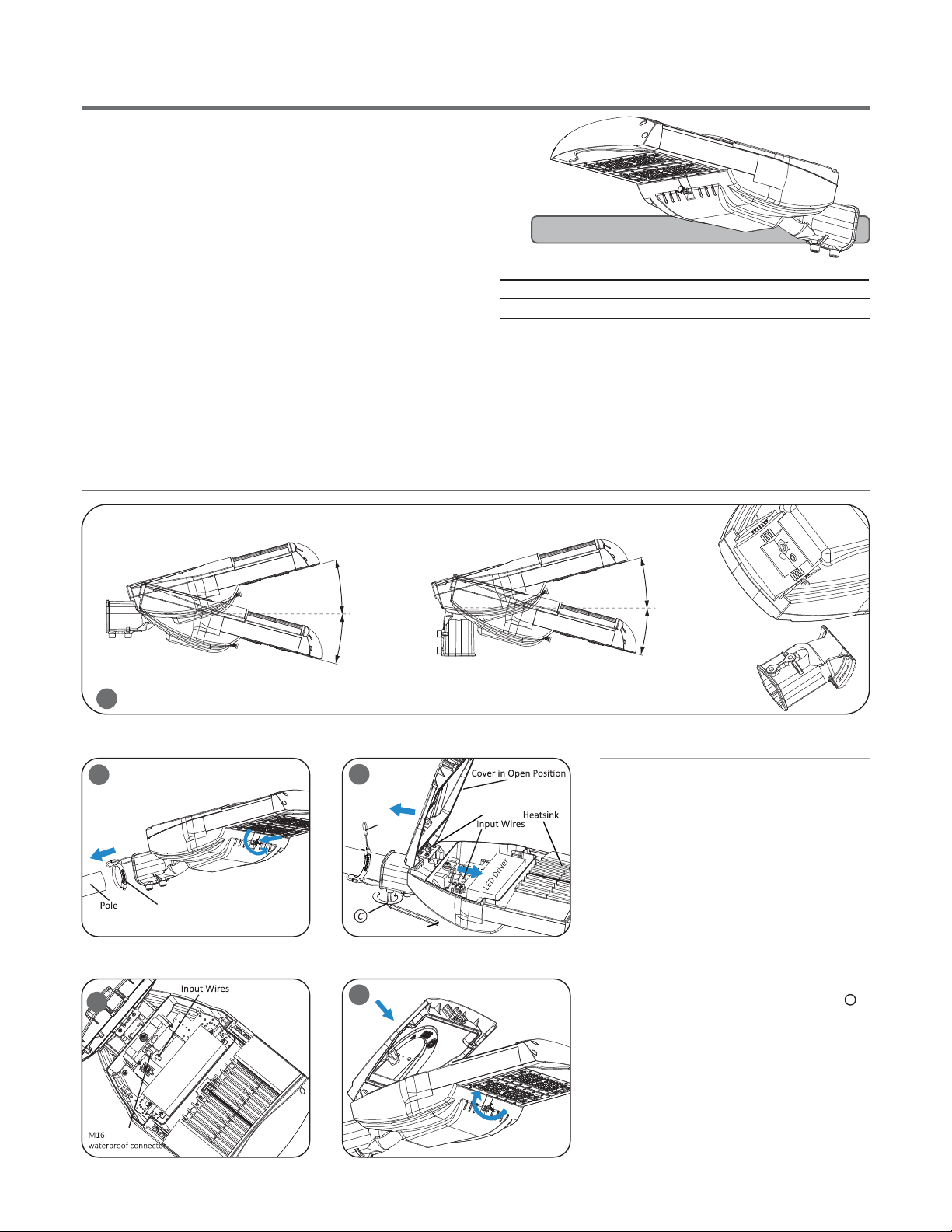
IMPORTANT
DC(Direct Current) based system.
DC BASED
STEP 1:
Make the following Electrical ConnecƟons:
a.
b.
Connect INPUT POSITIVE(+) conductor to RED WIRE posiƟon
of the terminal block or POSITIVE(+) conductor of LED driver.
Connect INPUT NEGATIVE(-) conductor to BLACK WIRE
posiƟon of the terminal block or NEGATIVE(-) conductor of
LED driver.
Connect INPUT DIM SIGNAL (WHITE WIRE) to Dim signal of
LED Driver.
STEP 2:
Make sure all excess input wires are pushed into pole, screws are
Ɵghtened.
STEP 3:
Close cover by rmly pushing cover towards xture, making sure
that no wires are pinched and Sealing gasket are fully engaged.
STEP 4:
If the xture without a terminal block, please insulate all electrical
connecƟons with wire nuts suitable for at least 90°C
TERMINAL BLOCK
LED DRIVER
NEGATIVE(-) NEGATIVE(-) BLACK
POSITIVE(+) POSITIVE(+) RED
+
-
INPUT WIRING
FIXTURE WIRING
This marking indicates that this product should not be disposed with other household wastes throughout the EU.
To prevent possible harm to the environment or human health from uncontrolled waste disposal, recycle it
responsibly to promote the sustainable reuse of material resources. To return your used device, please use
the return and collecƟon systems or contact the retailer where the product was purchased. They can take
this product for environmental safe recycling.
DIM Signal
(white)
c.
DIM Signal (White)
P.9/11

P.10/11
8.75
1.00
11
16
"
0.69
11
16
"
0.69
41
4
"
4.25
11.50
8.75
1.00
41
8
"
4.13
11
16
"
0.69
11
16
"
0.69
DRILLING PATTERN
OPTIONAL ELLIPTICAL POLE ARM #RE2MA AVAILABLE FOR THE ZX & TX SERIES.
HARDWARE 5/8-11X 3" (X2) INCLUDED FOR INSTALLING THE POLE ARM.
PLEASE COORDINATE DRILLING HOLES WITH YOUR POLE MANUFACTURER.
THE FIXTURES'S POLE ARM MUST BE INSTALLED AT A MINIMUM DISTANCE BELOW
THE TOP OF THE POST AS PER THE FOLLOWING TABLE. THE DISTANCE REFERS TO
THE BRACKET TOP MOUNTING HOLE.
DIMENSIONS IN INCHES
BACK
L = 24"
H = 12"
A = 2.5" x 3.375"
DIAM. EXT. = 2.375"
THICKNESS = 0.125"
REV.
DESCRIPTION
DATE
PAR
2
DIMENSIONS ADJUSTED
16 MAR 2023
JFOL
1
MOUNTING DETAIL & FRACTIONAL
MEASUREMENTS
19 SEP 2022
JFOL
0
ORIGINAL
26 MAI 2022
JFOL
DISTANCE MIN.
MODEL
18" (457mm)
ZX100, ZX170, TX150 & TX300
A A
B B
2
2
1
1
PROJECT:
WEIGHT:
0.125"
THICKNESS
THE INFORMATION CONTAINED IN THIS
DRAWING IS THE SOLE PROPERTY OF
VISION SOLAIRE INC ANY
REPRODUCTION IN PART OR AS A WHOLE
WITHOUT THE WRITTEN PERMISSION OF
VISION SOLAIRE COM IS
PROHIBITED.
PROPRIETARY AND CONFIDENTIAL
DIMENSIONS ARE IN INCHES
DEFAULT TOLERANCES:
ANGULAR
1°
TWO PLACE DECIMAL
.06"
THREE PLACE DECIMAL
.031"
HOLES
.005"
MATERIAL
FINISH
BLACK
DRAWN
DATE
NAME
ZX - TX
TITLE:
SIZE
A
DWG. NO.
REV
SCALE: 1:25
UNLESS OTHERWISE SPECIFIED:
JFOL
26 MAI 2022
SHEET 2 OF 2
RE2MA
DO NOT SCALE DRAWING
DRILLING PATTERN
ELLIPTICAL POLE
ARM 2'
6063-T6 ALU.
2
P.11/11
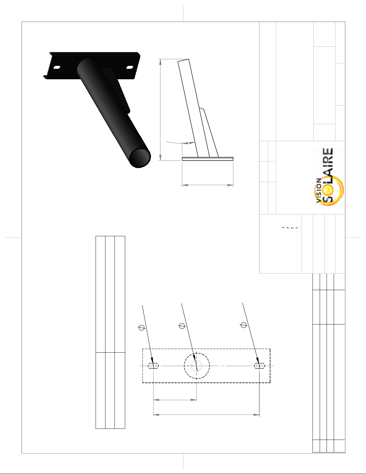
9.85
4.00
0.50
1.00
0.50
11.81
12°
23.50
OPTIONAL STRAIGHT POLE ARM AVAILABLE FOR THE ZX & TX SERIES
HARDWARE 3/8"-16X 1-3/4" (2X) INCLUDED FOR INSTALLING THE POLE ARM.
PLEASE COORDINATE DRILLING HOLES WITH YOUR POLE MANUFACTURER.
THE FIXTURE'S POLE ARM MUST BE INSTALLED AT A MINIMUM DISTANCE BELOW
THE TOP OF THE POST AS PER THE FOLLOWING TABLE:
DRILLING PATTERN
DIMENSIONS IN INCHES
DISTANCE MIN.
MODEL
12" (305mm)
ZX30 & ZX60
18" (457mm)
ZX100, ZX170, TX150 & TX300
REV.
DESCRIPTION
DATE
PAR
2 MOUNTING LOCATION
25 MAY 2022
JFOL
1
DIMENSIONS UPDATE
4 MAY 2022
JFOL
0
ORIGINAL
2 FEV 2022
JFOL
A A
B B
2
2
1
1
PROJECT:
WEIGHT:
"
THICKNESS
THE INFORMATION CONTAINED IN THIS
DRAWING IS THE SOLE PROPERTY OF
VISION SOLAIRE INC ANY
REPRODUCTION IN PART OR AS A WHOLE
WITHOUT THE WRITTEN PERMISSION OF
VISION SOLAIRE COM IS
PROHIBITED.
PROPRIETARY AND CONFIDENTIAL
DIMENSIONS ARE IN INCHES
DEFAULT TOLERANCES:
ANGULAR
1°
TWO PLACE DECIMAL
.06"
THREE PLACE DECIMAL
.031"
HOLES
.005"
MATERIAL
FINISH
DRAWN
DATE
NAME
ZX - TX
TITLE:
SIZE
A
DWG. NO.
REV
SCALE: 1:2
UNLESS OTHERWISE SPECIFIED:
JFOL
2 FEV 2022
SHEET 1 OF 1
RD212
DO NOT SCALE DRAWING
DRILLING PATTERN 2 FT
ARM @ 12DEG
FOR 4" & 5" POLE
PAINTED STEEL
2
This manual suits for next models
1
Table of contents
Other SOLAR VISION Lighting Equipment manuals


