Solarbotics The Paris Flyer CarouSol Kit Operator's manual

www.solarbotics.com 1-866-276-2687
solarbotics.com/products/60420/ Document revision: March 27 2018
Basic soldering & tools required 1-2 hours build time
Intermediate ages 12+skill level -
Solar powered
(no batteries needed)
Elegant airship travel cleverly
TM
powered with SolarEngine
Technology
Paris Flyer
The
CarouSol Kit

“The Trans-Atlantic TeslaTech Dirigible ‘Paris Flyer’ is about to depart for New
York City. Please stow your luggage and wait for our attendants to ensure you
are strapped in securely. We will be reaching a rotational velocity of 0.628
radians per second and maximum G-Force of approximately 4 times natural
during the launch cycle.
The approach to the Trans-Atlantic Ion energy channel will take approximately 9
minutes after launch, after which your harness will release and you may explore
your cabin. Enjoy the view from our climate-controlled viewing gondola while
we approach our maximum cruising altitude of 3000 meters, or settle in for a
meal from at our 4-star restaurant.
We thank you for flying TeslaTech Airways, and hope you enjoy your flight.”
Introduction
Kids, build your own model TeslaTech Dirigible like the ones that used to fly the Ion-
channels so long ago! We’re going to build a SolarEngine to wirelessly charge and
TM
power your airship, much like TeslaTech Ether-Engines used to do, but we’ll be
using solar energy rather than Ion channels.
Be prepared with appropriate soldering equipment for the electronics, and suitable
model-construction tools for the wood and mechanical assembly. When complete,
your model will activate between every 30 seconds in direct sunlight to every 5
minutes in indoor lighting, and you can imagine how it was to travel trans-
continentally in the age of TeslaTech!
Alternate history play-time fantasies aside, the Paris Flyer is a kit inspired by the
whimsy of creative wind-driven mobiles and the wonderful autonomy of self-
activating solar-powered energy.
TM
Unlike other solar-powered devices, our SolarEngine allows us to extract useful
energy from light levels otherwise unusable by solar cells. In direct sunlight,
activation happens in seconds; in an interior flourescent-lighted office, every 6
minutes. If there is sufficient light to read by, this device is still working.
We hope you enjoy the little story our model tells, and have fun with both the
mechanical and electrical assembly. As with all Solarbotics’ kits, we guarantee a
successful “no-fear” build, so do enjoy the process even you experience a broken or
lost part. Contact us, and we’ll set things right!
The Paris Flyer CarouSol Kit
1

PARTS LIST
ŸWhite glue / wood glue
ŸWire strippers (30AWG capable)
TOOLS REQUIRED
1 x Double-sided
sticky tape (DSST)
1 x SolarEngine
circuit board
Transistor 1381
Miller SolarEngine1.3 Solar
M
C2
D1
C1
ŸSoldering Iron
ŸSolder
4 x Laser cut wood panels
1 x Rotation point
& screw
1 x 3/4"
counter-
balance
1 x Spinning
surface
1 x Propeller
1 x Motor
2 x SCC3733 solar panel
2 x 13” long
30AWG wire
1 x Solar Engine:
1 x 0.22F capacitor* 1 x 22µF capacitor*
1 x Diode
1 x MCP112-195
voltage trigger
1 x TR2222
NPN transistor
The Paris Flyer CarouSol Kit
2
* - they look alike. (See Step 1.2) Pay particular attention to these capacitors

We will start by assembling the SolarEngine. This is a clever, simple
circuit that allows solar energy to be harvested and used in low light
levels - much lower than is usually possible. There is soldering
required, so if you are new to the process, review the “how-to” link
on the right.
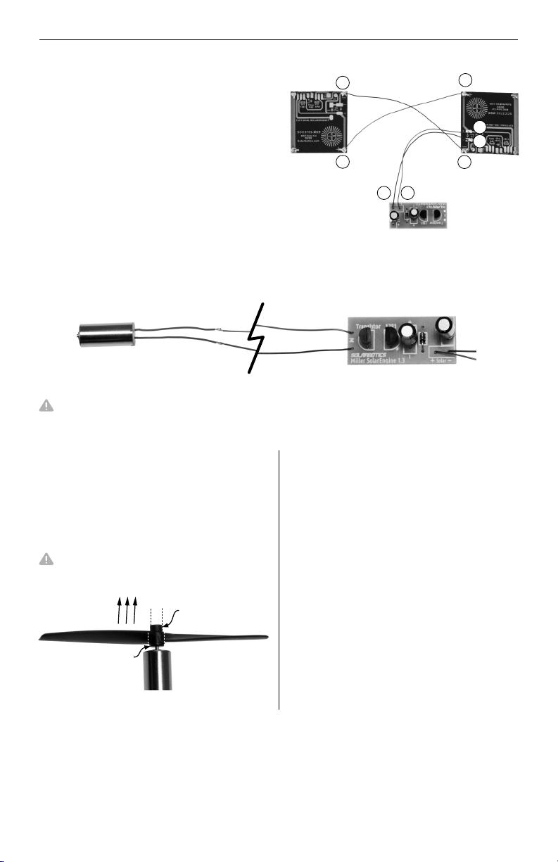
Find the transistor (A), trigger MCP112 (B) - (also
looks like a transistor), small 22 F capacitor (C) - the μ
one with paper on the legs, , small 0.22F capacitor (E)
and diode (D). Clip or peel any paper from the end
of the leads.
Install and solder the parts in as shown. Pay particular attention to the values marked
on capacitors. The capacitors are similar in physical size, but in fact are 10,000x
different electrically. The 22µF installs near the middle, where the 0.22F
(220,000µF!) is near the side.
1.2
Intro to soldering
slrbtcs.co/solderVid2
1.1
Back side
ASSEMBLY STEPS
1. SolarEngine Circuitry
Step
Small
22μF
capacitor (C)
Transistor (A)
(flat side
facing in)
Trigger (B)
(flat side
facing in)
Diode (D)
Polarity stripe
+
-
Front side
Small
0.22F
capacitor (E)
2.2
Cut four 3” pieces of wire (two of 1 color and two of the other) and remove 2mm of
insulation from each end with your wire strippers. Place your solar panels face down
and edge to edge as shown. Connect the positive of each solar panel together with a
wire, and the negative of
each panel with another
wire. Use opposite colors
for positive and negative.
Make sure to match the orientation markers & stripes. Make the stripes match the holes nearest the ‘-’
symbols. These components do not work backwards!
SolarEngine
circuit board (F)
The Paris Flyer CarouSol Kit
3
ASSEMBLY STEPS
2.3
+
-
+
-
+
-
+
-
Connect the positive pad of one solar
panel to the positive pad of the
SolarEngine and repeat this process for
the negative pads.
2.4
Don’t cross up the motor wiring. It will still work, but your dirigible will fly backwards!
Use the remaining wire to connect the motor to the SolarEngine. Strip the insulation
back 2mm and solder the pager motor wires to the wires from the SolarEngine.
2.5
Let’s test the propulsion setup to make
sure all is good. Gently press the prop
~1mm onto the end of the motor as
shown. It will still work backwards, but
with only about 70% as much thrust.
Place your solar panels in direct sunlight
or under incandescent light and wait 2-8
minutes, holding the motor so the
propeller can spin freely. When it
activates, you should feel it push air
away from the motor. If not, reverse the
motor wire connections.
Once it runs fine, insulate the bare
motor solder connections with a dab of
glue.
If you haven’t seen any action after 10
minutes, consult the Troubleshooting
section.
You get best thrust with the small diameter on
the propeller hub facing away from the motor.
After successfully testing the propulsion system, remove the propeller with your
fingernails or a small screwdriver. This makes it easier to add the motor into the
dirigible during final assembly.
2.6
smaller diameter
RED motor wire...
BLUE motor wire...
...still RED to this
connection
...still BLUE to
this connection
bigger diameter
desired
air flow
The Paris Flyer CarouSol Kit
4
ASSEMBLY STEPS
2. Assembling the Tower
Step
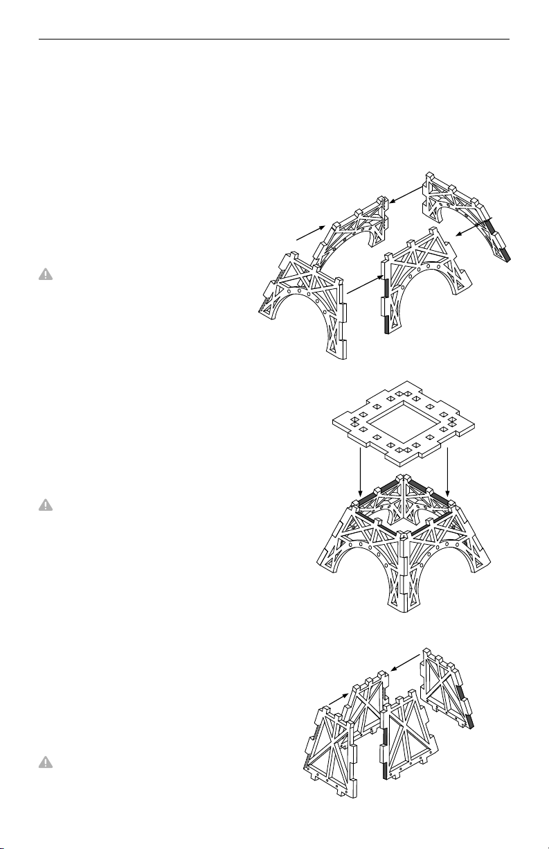
Remove the 4 tower bottom sections
(1) and remove cutouts. Apply glue to
each highlighted area, and fit each edge
together to create the three-
dimensional tower bottom.
2.1
All the laser cut parts are labeled and marked on the panel. Assembly is a simple
process of find, prepare, and assemble!
Remove the large platform (2) and
remove cutouts. Add glue to the indicated
areas and push the large platform down
onto the “fingers” of the tower bottoms.
2.2
You may need to wiggle the tower bottoms a
bit to get the fingers into the holes of the large
platform.
Do your best to complete all the
assembly before the glue dries. Being
able to wiggle components while putting
this together speeds construction.
Remove the 4 x tower middle section (3)
and remove cutouts. Add glue to each
area indicated and fit the edges together
to create the three-dimensional tower
middle.
2.3
Don’t pause here - complete step 2.4 before
letting the glue from this step completely cure.
The Paris Flyer CarouSol Kit
5
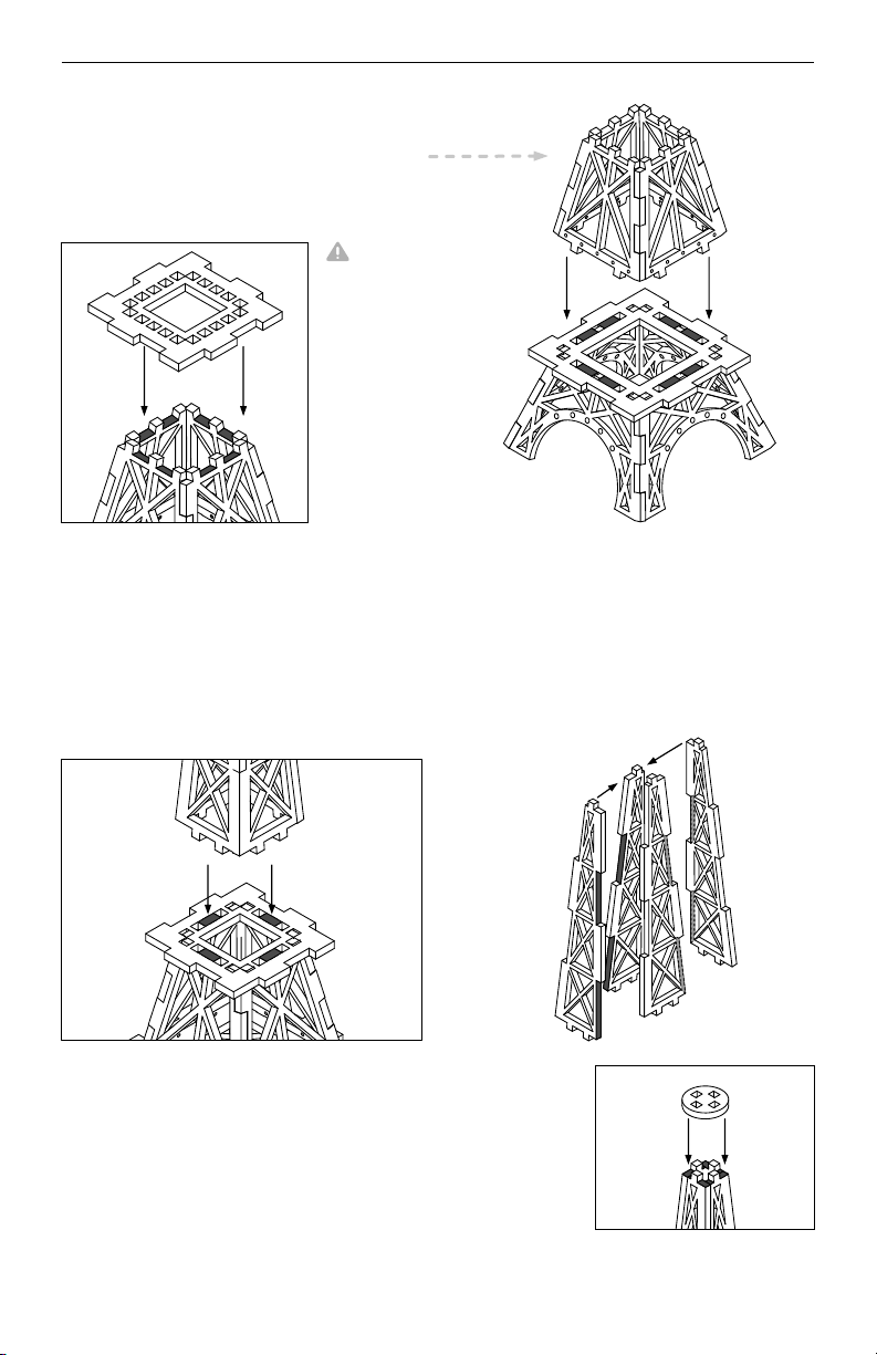
Remove the small platform (4) and remove cutouts. Add glue to the indicated areas
and push the small platform down onto the fingers of the tower middle section.
2.4
Remove the 4 x tower top parts (5) and
remove cutouts. Add glue to the indicated
areas and fit each edge together to create
the three-dimensional tower top.
Add glue to the indicated areas and
push the assembled top tower into the
holes on the small platform.
2.5
ASSEMBLY STEPS
Install the assembled middle tower into
the holes on the large platform.
Remove the tower cap (6) and remove any cutouts. Add
glue to the indicated areas and push the tower cap onto the
fingers of the tower tops.
2.6
2.3 cont’d
The Paris Flyer CarouSol Kit
6
You may need
to spread &
wiggle the
tower base
fingers to get
the fingers into
the holes of the
large platform.

Center and glue the spinner surface assembly to the tower
cap. Be generous with the glue to firmly secure it.
2.8
Remove the 4x bottom railings (8) and
remove cutouts. Add glue to the
indicated areas and slot the railings into
the notches on the large platform. We
need to keep the public on the viewing
platform safe!
2.9
Remove the 4x top railing (9) and
remove cutouts. Add glue to the
indicated areas and slot the railings into
the notches on the small platform.
2.10
ASSEMBLY STEPS
Find the spinner surface and place it face down (dome up) on a hard work surface.
Take the spinner ring (7) and push it onto the spinner surface so it “force fits” into
the spinner ring, so the edge of the spinner surface is flush with the ring.
3. Assembling
Step
the Counter Balance
3.1
Remove the balance base (10) and
remove cutouts. Cut the double sided
sticky tape (DSST) in half and use one
piece to stick the SolarEngine to the base
of the counterbalance power station
where shown. Make sure the wiring
orientation matches the illustration.
dome
side up
press ring
down onto
dome...
...flip over!
2.7
The Paris Flyer CarouSol Kit
7

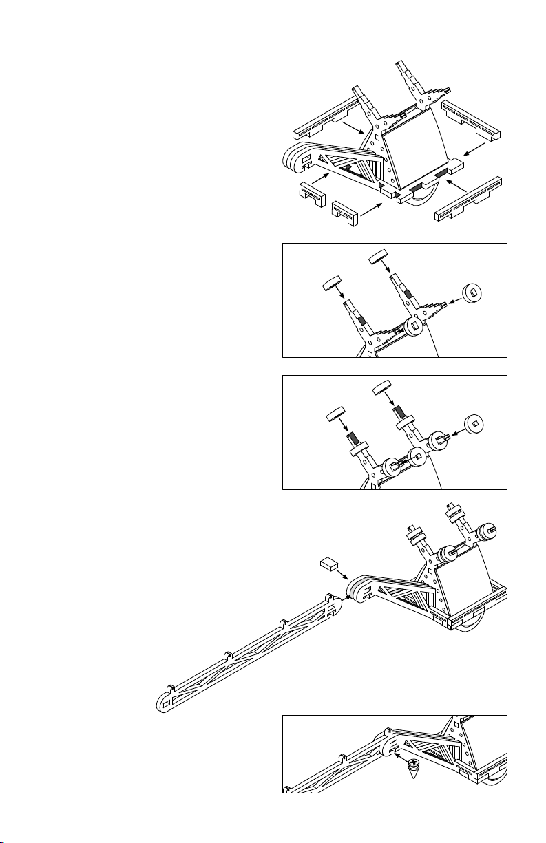
3.2
Remove the 2 x towers (11) and support
bar (12) and remove cutouts. Add glue
where shown, and attach a balance
tower to each side of the support bar.
Make sure the engraved detail lines on
the towers faces outwards.
3.3
Add glue where shown, and slot the
balance tower assembly into the holes
of the power station base.
3.4
Cut the remainder of the DSST into four
strips and stick them to the areas shown
here on each solar panel:
Do your best to keep all the wires we used to
attach the solar panels to the SolarEngine
hidden in between the two cells.
3.5
Remove the 2x balance holders (13)
and remove cutouts. Sandwich the 3/4"
ball bearing between the two balance
holders and slide the assembly into the
notches on the bottom of the power
station. The parts will snuggle into place,
and everything will lock together.
ASSEMBLY STEPS
PCB side of
the solar
cell
Stick each solar panel onto the power
station assembly. Rest the edge of the
solar panel on the base so that the
height of each solar panel is the same.
DSST strips
(photo above and
illustration below
are 180° rotated
from the top view)
The Paris Flyer CarouSol Kit
8
Remove the 2 x small railing (14),
medium railing (15), and 2 x large
railing (16) and remove cutouts. Add
glue and slot the railings into the
notches on the balance base.
3.6
Remove the 4 x large slot isolators (17)
and remove cutouts. Add glue, and slide
the isolators onto the power station
towers.
3.7
Remove the 4 x small slot isolators (18)
and remove cutouts. Add glue to the
indicated areas and slide the isolators
onto the balance towers.
3.8
Remove the balance arm (19) and
mounting pin tab (20) and remove
cutouts. Slot the balance arm between the
two balance holders and slide the
mounting pin tab into the hole so it goes
through all three pieces.
3.9
Pre-assemble the rotation point and
screw and slide it to the balance arm
assembly so the point sits in the middle of
the three pieces. Best to snug up the
screw during insertion, and force-slide it
the rest of the way.
3.10
ASSEMBLY STEPS
The Paris Flyer CarouSol Kit
9

4. Assembling the Dirigible
Step
4.1
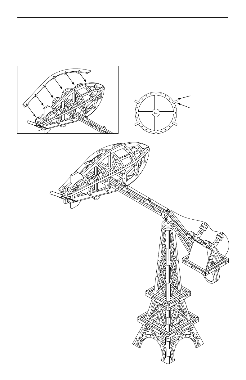
Remove the bottom rib (21), top rib
(22) and frame ribs (23-28) and remove
cutouts. Attach each ring to the bottom
rib, starting with (23) on the left and
continuing to (28) on the right. Once the
rings are in place, attach the top rib to
the top notch of each ring so that it
mirrors the bottom rib.
4.2
Remove mounting peg (29), and
mounting ring (30) and remove cutouts.
Push the mounting peg through frame
rib (25), through the balance arm
assembly, through the mounting circle,
and into frame rib (26). Glue the
balance arm and mounting circle where
they shoulder up to each other.
4.3
Install the motor & wire assembly next, starting by snugging the wires into each of
the tower tips as shown. At the dirigible frame, fish the wires through frame rib (25)
and (24), and insert the motor into the hole of frame rib (23). The motor will stick
out the back of the dirigible just enough so that the propeller just clears the rear of
the airship.
4.4
While supporting the rear of the motor, firmly press
the propeller onto the motor shaft, just like you did in
step 2.5.
Remember, a propeller installed backwards
still works, but at a much reduced efficiency.
ASSEMBLY STEPS
(23)
(24)
(25)
(26)
(27) (28)
The Paris Flyer CarouSol Kit
10
(29)
(30)
(26)
(25)
4.5
With the motor installed, you can finish assembly of the airship. Remove the rest of
the ribs (31-34) and assemble them as shown with dabs of glue where needed.
ASSEMBLY STEPS
The ribs look best when installed with the
clean side up, as shown below:
clean side up
laser-charred
side down
4.6
With the dirigible fully finished, balance
the assembly onto the top of the tower.
By design, it should balance practically
level, but if you find it is leaning to one
side, review the Troubleshooting section
for solutions.
For best effect, place it in a well-lighted
area. Even the top shelf of an office
bookcase near a fluorescent fixture
gives a pleasing performance.
(31)
(32) (33)
(34)
The Paris Flyer CarouSol Kit
11

The balance arm is not sitting horizontal:
1. Are you missing any parts? Each part is factored into the balance of the device. If
even one of the slot isolators of Step 3.7 & 3.8 are missing, the balance will be
thrown off. Make sure every part of the device is installed. If necessary, add a small
scrap of extra wood to the airship or power station until it’s balanced, and glue them
in place in a hidden area.
2. Are there any cutouts you forgot to remove? These cutouts can affect the balance
significantly and should all be removed for the device to balance properly.
The airship is tipped forwards or backwards:
1. Is the airship balance arm fully seated on the airship mounting peg of Step 4.2? If
not, this can shift the weight of the blimp so that it isn't correctly balanced on the
balance arm. Re-read Step 4.2 and confirm that your balance arm is correctly
located.
2. Is your rotation point centered between the balance holders and balance arm? If
the point is not centered, it can easily cause the airship to lean.
3. Are you missing any parts? A missing part can easily cause a shift in balance. Make
sure every part of the device is present and assembled.
4. Are there any cutouts you forgot to remove? These cutouts can affect the balance
significantly and should all be removed for the device to balance properly.
The airship travels backwards when the SolarEngine activates:
Your airship has the propeller mounted on the back, and should push it forward. If
not, simply reverse the motor connection wires where convenient.
The SolarEngine doesn't activate (and/or the propeller doesn't spin):
The Solarengine activity depends directly on light intensity. For testing, be in sunlight
or near an incandescent or halogen (not fluorescent) lamp. A soldering error is 9 out
of 10 times the reason a SolarEngine doesn't work. Inspect closely for parts not
connecting (too little solder) or connecting where it shouldn’t (too much solder).
Specifically, review the following:
Are any components backwards? Compare the components to the markings on the
SolarEngine and to the pictures of Step 1. Backwards components need to be flipped
around. Use a solder suckers or solder braid to remove the solder from the board, to
allow the removal & reinstallation of the problem component(s).
Are your solar panels connected correctly? Just like a battery, your project won’t
work if either (or both) solarcells are connected backwards. Check Step 1 to make
sure that your solar panels are connected correctly.
TROUBLESHOOTING
The Paris Flyer CarouSol Kit
12
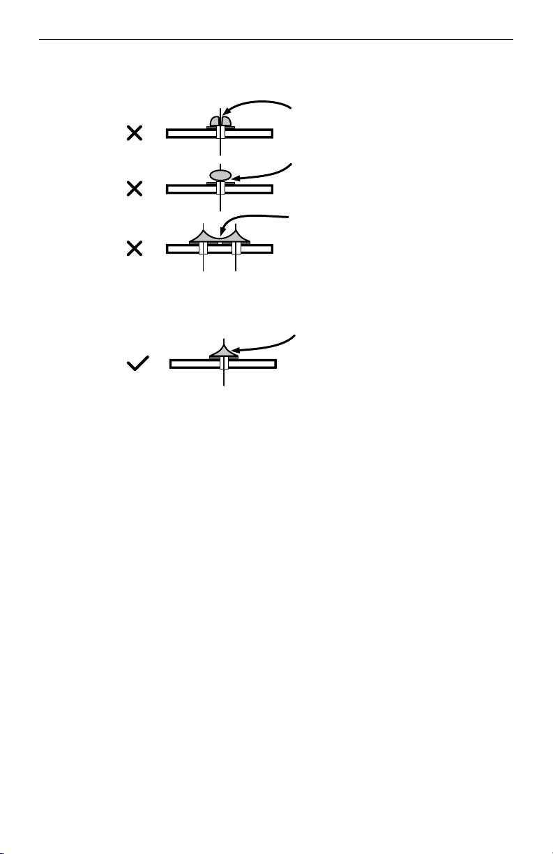
TROUBLESHOOTING
No flow from leg to pad
Solder “bridge” across pads
No flow from leg to pad
Flows from leg to pad
Good solder joint should look like this:
Additional Enhancements:
•If you are so inclined, a drop of oil in the spinner dome where the rotation point
sits will additionally reduce friction for even more rotational performance.
•Flex the wires from the power station to the airship with a suitable “sag” to give
them a weighty appearance.
•Feel creative? Use a bronze or silver marker to paint the beam superstructure and
airship framework. A darker color on the tower will give it a more “ironwork”
appearance.
•Intentionally pitch the nose up or down by playing with the installation at step 4.2,
which can add a pleasing “bob” to the circular motion of the Paris Flyer.
•Particularly hobby-skilled? Use diluted white glue, fine brush and tissue to “skin”
the airship (much like in classic model aircraft construction).
•If you are so inclined to play with electronics, changing the storage capacitor from
0.35F to 4700µF results in much more propeller activity in trade for less rotational
speed. You will have to rebalance the system for level.
•Convert your Paris Flyer to battery power by directly replacing the solarcells with
replaceable coin-cells. As the battery dies, the SolarEngine will start pulsing the
power out.
The Paris Flyer CarouSol Kit
13

GraviTrack - Solar Edition
bit.ly/2y6Aqj0
bit.ly/2xKEp3O
Liked the Paris Flyer?
Check out our GraviTrack Marble Machine family:
GraviTrack - Battery Edition

3740D - 11A Street NE
Suite 101
Calgary, Alberta T2E 6M6
Canada
This work is licensed under a Creative Commons
Attribution-ShareAlike 3.0 Unported License.
Visit us online for more info and cool stuff:
Made in Canada
1-866-276-2687 (TOLL FREE)
MON-FRI, 9AM- 5PM MST
Questions or
comments?
Let us know!
www.solarbotics.com
Solarbotics Ltd. is not responsible for any special, incidental, or consequential damages resulting from any breach of warranty, or under any legal
theory, including lost profits, downtime, good-will, damage to or replacement of equipment or property, and any costs or recovering of any material or
goods associated with the assembly or use of this product. Solarbotics Ltd. reserves the right to make substitutions and changes to this product without
prior notice. Keep out of reach of children. Product contains small parts, even when assembled, that might be a choking hazard for children under five.
© 2018 Solarbotics Ltd. All rights reserved. Parts, quantities, features and specifications are subject to change without notice. All other trademarks are
property of their respective owners. “SOLARBOTICS” is a trademark of Solarbotics Ltd. Reg. CIPO / USPTO.
Aggressive feline interaction damage? Obtuse canine posterior oscillation disaster?
Plain old damage during construction? No issue. Contact [email protected]om
and we’ll make sure you get the replacement parts (most often free of charge) to
have a successful build experience! We guarantee a successful build!
Solarbotics “No Fear” Warranty
bit.ly/2HM0o49
See it in action:
Table of contents
Other Solarbotics Toy manuals

Popular Toy manuals by other brands


Alexander
Alexander Origami 3D Ladybug 2568 manual

Fisher-Price
Fisher-Price W9740 instruction sheet

Faber
Faber Inca Lux Glass instruction manual

Tiger Electronics
Tiger Electronics Pooh Poppin' Piano 87-001 instruction manual

FUTABA
FUTABA GV-1 instruction manual

Hasbro
Hasbro furReal Rollies quick start guide


