SolarCity H6 Original operating instructions

H6 Hybrid Inverter
Installation & Operation Guide

H6 Hybrid Inverter - Installation & Operation Guide
ii Copyright 2017 SolarCity Corporation. All rights reserved.
COPYRIGHT NOTICE
SolarCity H6 Inverter Installation & Operation Manual, v1.1 (02/2017)
©2017 by SolarCity Corporation, 3055 Clearview Way, San Mateo, CA 94402
phone: (650) 638-1028, fax: (650) 560-6460;
www.solarcity.com
.
No part of this document may be reproduced, stored in a retrieval system, or transmitted, in
any form or by any means, be it electronic, mechanical, photographic, magnetic or other-
wise, without the prior written permission of SolarCity Corporation.
SolarCity Corporation makes no representations, express or implied, with respect to this
documentation or any of the equipment and/or software it may describe, including (with no
limitation) any implied warranties of utility, merchantability, or fitness for any particular pur-
pose. All such warranties are expressly disclaimed. SolarCity Corporation shall not be liable
for any indirect, incidental, or consequential damages under any circumstances.
(The exclusion of implied warranties may not apply in all cases under some statutes, and thus
the above exclusion may not apply.)
Specifications are subject to change without notice. Every attempt has been made to make
this document complete, accurate and up-to-date. Readers are cautioned, however, that
SolarCity Corporation reserves the right to make changes without notice and shall not be
responsible for any damages, including indirect, incidental or consequential damages, caused
by reliance on the material presented, including, but not limited to, omissions, typographical
errors, arithmetical errors or listing errors in the content material.
All trademarks are recognized even if these are not marked separately. Missing designations
do not mean that a product or brand is not a registered trademark.

iii
Copyright 2017 SolarCity Corporation. All rights reserved.
Table of Contents
1 - Welcome ..........................................................................................1
1.1 - Qualification of Skilled Workers.................................................................................5
1.2 - General H6 Features.................................................................................................5
1.3 - Package Contents.....................................................................................................6
1.4 - Additional Tools .......................................................................................................6
1.5 - About This Manual ....................................................................................................7
1.5.1 - Formatting Conventions ....................................................................................7
1.5.2 - Safety Symbols .................................................................................................8
1.5.3 - Layout..............................................................................................................9
1.6 - Related Documentation .......................................................................................... 10
1.7 - Additional Resources .............................................................................................. 10
1.8 - Technical Support .................................................................................................. 10
2 - Safety Instructions .......................................................................... 11
2.1 - General...................................................................................................................11
2.2 - SolarCity H6 Inverter.............................................................................................. 12
2.3 - Safety Labels ......................................................................................................... 14
2.4 - Battery Pack Safety ................................................................................................ 15
3 - Overview ........................................................................................ 17
3.1 - Layout ....................................................................................................................17
3.2 - Dimensions & Clearances .......................................................................................20
3.2.1 - Inverter Dimensions........................................................................................20
3.2.2 - Clearances .................................................................................................... 21
3.3 - Inverter Mounting Bracket......................................................................................22
3.3.1 - Standard 16” Wall ...........................................................................................23
3.3.2 - 24” Wall ........................................................................................................24
3.3.3 - Single Pillar....................................................................................................24
3.3.4 - Masonry or Concrete Walls.............................................................................24
3.4 - DC and AC Switches...............................................................................................25
3.4.1 - DC Disconnect Switch.....................................................................................25
3.4.2 - AC Bypass Switch ...........................................................................................26
3.5 - Inverter Wiring Box ................................................................................................ 27
3.5.1 - PV Interface ...................................................................................................28
3.5.2 - Battery Pack Interface.................................................................................... 31
3.5.3 - Communications............................................................................................ 31
3.5.4 - Backup/Protected Loads Panel ......................................................................32
3.5.5 - AC Grid Point of Interconnection....................................................................34

H6 Hybrid Inverter - Installation & Operation Guide
iv Copyright 2017 SolarCity Corporation. All rights reserved.
3.6 - Whole-Home Backup at the Main Panel ..................................................................35
3.6.1 - Mechanical Interlock Kit on the Main Panel...................................................... 35
3.6.2 - Mechanical Interlock Kit on a Separate Manual Transfer Switch.......................36
3.6.3 - Sources for MIK and MTS Products................................................................. 37
3.7 - External Components............................................................................................. 37
3.7.1 - PV Array ......................................................................................................... 37
3.7.2 - Battery Pack ..................................................................................................38
3.7.3 - Back-up Electrical Panel................................................................................. 39
3.7.4 - Main Electrical Panel ...................................................................................... 41
3.8 - Fireman Switch and Rapid Shutdown......................................................................42
3.8.1 - Components ..................................................................................................42
3.8.2 - System Diagram .............................................................................................43
3.8.3 - Fireman Switch Sequence ..............................................................................44
3.8.4 - DC Disconnect Switch Sequence ....................................................................45
4 - Installation .....................................................................................47
4.1 - Visual Inspection....................................................................................................48
4.2 - Selecting a Location ..............................................................................................48
4.3 - Mounting the Inverter ............................................................................................50
4.3.1 - Installing the Inverter Mounting Bracket ...........................................................51
4.3.2 - Hanging the Inverter ...................................................................................... 52
5 - Electrical Connections.....................................................................55
5.1 - System Wiring Diagrams.......................................................................................... 57
5.2 - Wiring Box Cover ................................................................................................... 59
5.2.1 - Remove Wiring Box Cover ...............................................................................59
5.2.2 - Refit Wiring Box Cover ...................................................................................60
5.3 - Conduit Plugs and Fittings.......................................................................................61
5.4 - Grounding Connections......................................................................................... 62
5.5 - Using the Spring Clamp Connectors ....................................................................... 62
5.6 - PV Connections .....................................................................................................63
5.6.1 - Limitations.....................................................................................................64
5.6.2 - Wiring ...........................................................................................................64
5.7 - Battery Pack Connections ......................................................................................65
5.7.1 - Wiring ............................................................................................................65
5.7.2 - Fuses.............................................................................................................66
5.7.3 - Communications............................................................................................66
5.8 - AC Voltage ............................................................................................................ 67
5.8.1 - Output to Grid ............................................................................................... 67
5.8.2 - Utility Back-Feed (OCPD) Circuit Breaker........................................................ 68
5.8.3 - Output to Backup Load Center....................................................................... 68
5.9 - Communications ...................................................................................................69
5.9.1 - ZigBee & Gateway...........................................................................................69
5.9.2 - Integrated Revenue Grade Meter (RGM) ..........................................................69
5.9.3 - PV-Only Charging...........................................................................................69

v
Copyright 2017 SolarCity Corporation. All rights reserved.
Table of Contents
5.9.4 - Rapid Shutdown (RSD)....................................................................................70
5.9.5 - Dark-Start Feature.........................................................................................70
5.9.6 - Fireman Switch ...............................................................................................71
6 - User Controls..................................................................................73
6.1 - Displays and Buttons .............................................................................................. 73
6.1.1 - Status LEDs ..................................................................................................... 75
6.1.2 - LCD Display .................................................................................................... 76
6.1.3 - Push Buttons.................................................................................................. 76
6.2 - Menu Structure...................................................................................................... 77
6.2.1 - System Overview Menu ................................................................................... 77
6.2.2 - Current Status Menu ...................................................................................... 79
6.2.3 - External Messages Menu................................................................................. 79
6.2.4 - Software Versions Menu ................................................................................. 79
6.2.5 - Clear Fault Menu............................................................................................80
6.2.6 - Soft Shutdown Menu ......................................................................................80
6.2.7 - Grid Settings Menu .........................................................................................80
6.2.8 - ZigBee (Xbee) Information Menu ..................................................................... 81
7 - Commissioning ............................................................................... 83
8 - Basic Operation.............................................................................. 85
8.1 - Powering On the Inverter........................................................................................85
8.2 - Powering Off the Inverter.......................................................................................86
8.3 - Bypassing the Inverter............................................................................................86
8.4 - Opening/Closing the Inverter.................................................................................86
8.5 - Power Flow Modes................................................................................................. 87
8.5.1 - PV to Battery Pack .......................................................................................... 87
8.5.2 - PV to AC Grid Output ..................................................................................... 87
8.5.3 - PV to Protected Home Loads.......................................................................... 87
8.5.4 - Battery Pack to AC Grid Output ...................................................................... 87
8.5.5 - Battery Pack to Protected Home Loads...........................................................88
8.5.6 - AC Grid to Protected Home Loads ..................................................................88
8.5.7 - AC Grid to Battery Pack ..................................................................................88
8.5.8 - On-Grid to Off-Grid Status.............................................................................89
8.5.9 - Off-Grid to On-Grid Status.............................................................................89
9 - Product Information ........................................................................ 91
9.1 - Specifications ........................................................................................................ 91
9.1.1 - General........................................................................................................... 91
9.1.2 - Mechanical.....................................................................................................92
9.1.3 - PV Input .........................................................................................................92
9.1.4 - AC Output ......................................................................................................93
9.1.5 - Battery Pack Interface ....................................................................................93

H6 Hybrid Inverter - Installation & Operation Guide
vi Copyright 2017 SolarCity Corporation. All rights reserved.
9.2 - Protection Features...............................................................................................94
9.2.1 - Arc Fault Circuit Interrupter ...........................................................................94
9.2.2 - Anti-Islanding Protection ...............................................................................94
9.2.3 - Reverse Polarity.............................................................................................94
9.2.4 - Residual Current Detection (RCD) ..................................................................94
9.2.5 - Fireman Switch..............................................................................................94
9.2.6 - RISO (PV Insulation Resistance Monitor)..........................................................95
9.3 - Standards & Directives...........................................................................................95
9.4 - Communication.....................................................................................................95
9.5 - Thermal, Voltage, and Efficiency Charts.................................................................. 96
9.5.1 - Thermal De-rating .......................................................................................... 96
9.5.2 - PV Voltage and AC Output Power.................................................................... 97
9.5.3 - PV Input Voltage and Efficiency ......................................................................98
9.5.4 - Battery Pack Round-Trip (Charging & Discharging) Efficiency...........................99
9.6 - Regulatory Approvals ........................................................................................... 100
9.6.1 - FCC Compliance .......................................................................................... 100
9.6.2 - UL Certificate ............................................................................................... 101
10 - Troubleshooting and Maintenance.................................................. 103
10.1 - Intended Uses .................................................................................................... 103
10.2 - General Troubleshooting .................................................................................... 103
10.3 - Alarms, Faults, and Warnings .............................................................................. 105
10.3.1 - Alarms ........................................................................................................ 105
10.3.2 - Faults......................................................................................................... 106
10.3.3 - Warnings.................................................................................................... 108
10.4 - Replacing the Inverter ........................................................................................ 109
10.4.1 - Inverter (Remove) ....................................................................................... 109
10.4.2 - Inverter (Refit) ............................................................................................ 110
10.5 - Replacing Internal Components ........................................................................... 113
10.5.1 - Fuses........................................................................................................... 115
10.5.2 - Fan ............................................................................................................. 116
10.5.3 - PLC Transmitter .......................................................................................... 116
10.5.4 - ZigBee Chip ................................................................................................ 118
10.5.5 - 9-Volt Battery .............................................................................................120
10.6 - Warranty and Returns ......................................................................................... 121
A - Glossary....................................................................................... 123

vii
Copyright 2017 SolarCity Corporation. All rights reserved.
Table of Contents
B - SMART Rapid Shutdown Slave.......................................................... 127
B.1 - Dimensions and Clearances .................................................................................. 128
B.1.1 - SMART RSS Dimensions.................................................................................. 128
B.1.2 - Clearances ................................................................................................... 129
B.2 - Installing the SMART RSS ...................................................................................... 130
B.3 - Removing the SMART RSS ..................................................................................... 132
B.4 - Grounding the SMART RSS.................................................................................... 133
B.5 - Warning Label ..................................................................................................... 133
B.6 - Self-Test ............................................................................................................. 133
B.7 - Specifications...................................................................................................... 134
B.7.1 - Mechanical ................................................................................................... 134
B.7.2 - Ratings ........................................................................................................ 134
B.7.3 - Compliance ................................................................................................. 135

H6 Hybrid Inverter - Installation & Operation Guide
viii Copyright 2017 SolarCity Corporation. All rights reserved.
This page intentionally left blank.

ix
Copyright 2017 SolarCity Corporation. All rights reserved.
List of Figures
Figure 1-1: Typical PV installation with a SolarCity H6 inverter ............................................3
Figure 1-2: Block diagram of a complete SolarCity H6 inverter installation..........................4
Figure 1-3: Ratchet wrench, long-shank screwdriver, and chip puller................................. 7
Figure 2-1: SolarCity H6 safety labels .............................................................................. 14
Figure 3-1: SolarCity H6 inverter with callouts ..................................................................17
Figure 3-2: SolarCity H6 inverter dimensions (front view) ................................................20
Figure 3-3: SolarCity H6 inverter dimensions (bottom view) .............................................20
Figure 3-4: Minimum clearances (below)......................................................................... 21
Figure 3-5: SolarCity H6 Inverter Mounting Bracket with hooks........................................22
Figure 3-6: Installing the Inverter Mounting Bracket on various wall types ........................23
Figure 3-7: DC Disconnect Switch in ON position ............................................................25
Figure 3-8: DC Disconnect Switch in OFF position ...........................................................25
Figure 3-9: AC Bypass Switch in the INV position.............................................................26
Figure 3-10: AC Bypass Switch in the BYP position ...........................................................26
Figure 3-11: SolarCity H6 inverter wiring box connections ................................................ 27
Figure 3-12: Wiring box label .......................................................................................... 27
Figure 3-13: Parallel string connections ..........................................................................29
Figure 3-14: Fireman Switch connections........................................................................30
Figure 3-15: Fireman Switch operation (below)................................................................30
Figure 3-16: DC Disconnect Switch operation (below) ......................................................30
Figure 3-17: High-voltage battery pack connections......................................................... 31
Figure 3-18: Communications connections (colors may vary)............................................32
Figure 3-19: Backup load connections.............................................................................33
Figure 3-20: AC grid POI output connections ..................................................................34
Figure 3-21: Mechanical Interlock Kit (MIK) Installed on a Main Panel ................................35
Figure 3-22: Mechanical Interlock Kit (MIK) Installed on a Manual Transfer Switch (MTS) ....36
Figure 3-23: RSS components and wiring ........................................................................43
Figure 4-1: Inverter orientation.......................................................................................49

H6 Hybrid Inverter - Installation & Operation Guide
xCopyright 2017 SolarCity Corporation. All rights reserved.
Figure 4-2: Hanging the SolarCity H6 inverter on the mounting bracket ...........................53
Figure 5-1: SolarCity H6 installation wiring diagram (1 of 2) .............................................. 57
Figure 5-2: SolarCity H6 installation wiring diagram (2 of 2) .............................................58
Figure 5-3: Removing the wiring box cover and close-up of screw head...........................60
Figure 5-4: Rain-tight compression connector ................................................................61
Figure 5-5: Using the spring clamp connectors ...............................................................63
Figure 5-6: Fireman Switch .............................................................................................71
Figure 6-1: SolarCity H6 inverter LEDs, LCD display, and buttons ..................................... 73
Figure 6-2: Interpreting the SolarCity H6 inverter LEDs ................................................... 75
Figure 9-1: Temperature de-rating graph ........................................................................96
Figure 9-2: AC Output power vs. PV input voltage range .................................................. 97
Figure 9-3: CEC Efficiency vs. PV input voltage ............................................................... 98
Figure 9-4: Battery pack charging efficiency ...................................................................99
Figure 9-5: Battery pack discharging efficiency...............................................................99
Figure 10-1: Removing the SolarCity H6 inverter top section ........................................... 110
Figure 10-2: Wires from inverter top section to wiring box ............................................. 112
Figure 10-3: Internal components (with separate PLC, top; with integrated PLC, bottom) 113
Figure 10-4: ZigBee chip with circuit breaker cover removed.......................................... 119
Figure 10-5: 9-Volt Battery (unit with separate PLC, top; with integrated PLC, bottom) ...120
Figure B-1: SMART RSS dimensions ................................................................................128
Figure B-2: Minimum SMART RSD clearances..................................................................129
Figure B-3: Installing the SMART RSS (below).................................................................. 131
Figure B-4: Removing the SMART RSS ............................................................................132

1
Copyright 2017 SolarCity Corporation. All rights reserved.
1 - Welcome
This guide describes the safety, installation, commissioning, operation, troubleshooting and
maintenance of the SolarCity H6 inverter. The inverter may or may not include a pre-installed
Power Line Communication (PLC) Transmitter.
The H6 inverter is a bidirectional, multi-mode (hybrid) inverter that can:
Convert direct current (DC) from both PV modules (photovoltaic modules, also called solar
panels) and batteries into alternating current (AC) that is synchronized to interface with the
utility grid voltage.
•Charge an external battery pack with power harvested from the PV modules.
•Discharge battery pack power to operate home loads.
•Supply PV-generated power to the utility grid.
•Pass through utility power to selected home loads via the backup electrical panel.
•Charge an external battery pack with power supplied by the electrical grid (only if
permitted by the local utility).
The SolarCity H6 inverter is a transformer-less multi-mode inverter that meets all UL 1741
and IEEE 1547 requirements that uses efficient Maximum Power Point (MPP) tracking to
achieve maximum power output. The wide MPP range supports a variety of PV modules from
a variety of manufacturers, with a maximum no-load (open circuit) voltage of 570V. Maximum
WARNING: THIS MANUAL IS FOR USE BY QUALIFIED PERSONNEL ONLY.
QUALIFIED PERSONNEL ARE THOSE WHO HAVE RECEIVED TRAINING AND
HAVE DEMONSTRATED SKILLS AND KNOWLEDGE IN THE COMMISSIONING
AND OPERATION OF THIS DEVICE, AND WHO ARE TRAINED IN MITIGATING
THE DANGERS AND HAZARDS INVOLVED IN INSTALLING ELECTRICAL
DEVICES.
Note: This guide includes general information about third-party accessory
devices that are connected to the H6 inverter. Please refer to the third-
party device documentation for detailed information and specifications
for those devices.
Note: Store this guide in a readily accessible location.
H6 Hybrid Inverter - Installation & Operation Guide
2Copyright 2017 SolarCity Corporation. All rights reserved.
no-load voltage occurs at the lowest-anticipated temperatures. Please refer to the PV
module documentation for detailed temperature dependency information.
The SolarCity H6 inverter contains an internal automatic transfer relay that enables off-grid
operation. Protected home loads (also called protected loads) are loads extended from an
existing electrical panel and placed into a new electrical panel called the “backup panel.”
Protected home loads operate with standby PV and/or battery pack power when grid power
is not available.
Power from the solar array charges the battery pack during the day. The operating voltage of
the battery pack must correspond to the battery pack input voltage range on the battery
pack interface of the SolarCity H6 inverter. The battery pack management system (BMS)
records critical information (DC current, voltage, power, SOC, temperature, faults, etc.)
when charging and discharging the battery pack and reports to the inverter on a continuous
basis.
Figure 1-1
on the next page depicts a typical home installation.
Note: Balance of Systems (BOS) refers to hardware that is used in the
installation of this system, including but not limited to wires, conduits,
boxes, etc.
Note: The combination of PV arrays, SolarCity H6 inverter, battery pack,
backup electrical panel, any accessories, BOS, and main electrical panel is
referred to as an Energy Storage System (ESS).
WARNING: INSTALLATION OF ANY OTHER BATTERY PACK THAN THE TYPE
SPECIFICALLY SUPPORTED BY THE H6 INVERTER WILL VOID THE
INVERTER WARRANTY.
3
Copyright 2017 SolarCity Corporation. All rights reserved.
Chapter 1 - Welcome
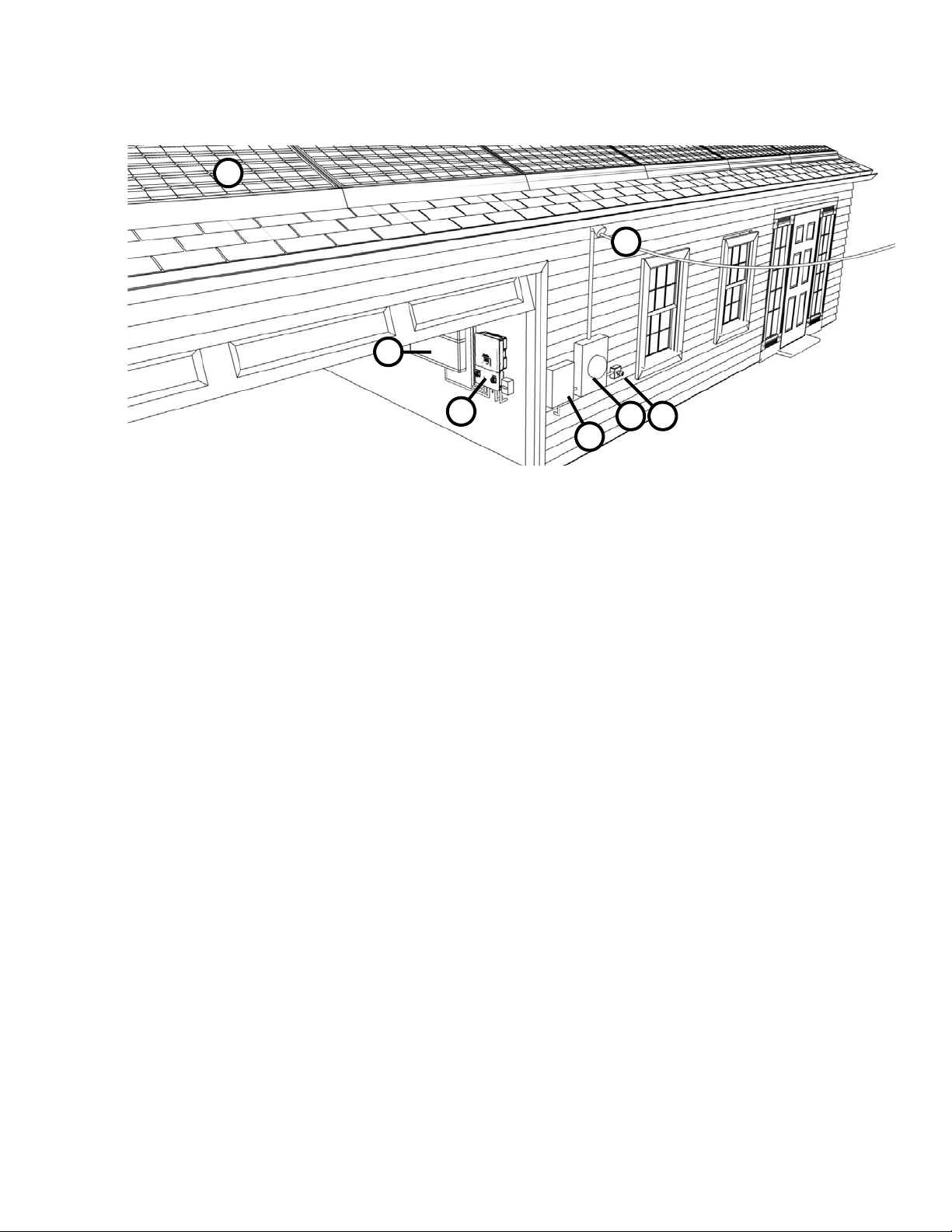
Figure 1-1: Typical PV installation with a SolarCity H6 inverter
The numbered callouts in
Figure 1-1
refer to the following:
•PV panels (1): Roof-mounted solar panels.
•Utility grid (2): Source of AC power from the utility company.
•Battery Pack (3): Stores electrical energy for use by the protected home loads when grid
power is offline and PV energy is insufficient to meet demand. The battery pack feeds DC
current to the inverter, which converts it to AC current for use by the protected home
loads.
•SolarCity H6 inverter (4): Converts DC current from the panels/battery pack into AC
current for use by the protected home loads and charges the battery pack when there is
enough PV energy available to do so.
•Backup/Protected Loads Panel (5): Distribution panel for the loads that are protected by
the Battery Pack.
•Main Panel (6): Main distribution panel for the building. This panel includes a 35A breaker
for the PV point of interconnection. If sufficient solar energy is available, the inverter will
feed power to the non-protected home loads via this breaker and the main panel.
•Optional Fireman Switch (7): Quickly de-energizes all DC circuits in the event of an
emergency.
1
2
3
47
6
5

H6 Hybrid Inverter - Installation & Operation Guide
4Copyright 2017 SolarCity Corporation. All rights reserved.
Figure 1-2
depicts a block diagram of a completed SolarCity H6 inverter installation.
Figure 1-2: Block diagram of a complete SolarCity H6 inverter installation
The SolarCity H6 inverter includes various safety features, such as:
•Integrated DC arc-fault circuit interrupter (AFCI) per NEC 2014 690.11 that complies with
UL1699B requirements for Type 1 devices.
•Rapid shutdown (RSD) mechanism per NEC 2014 690.12 is achieved through two parts:
One part is the PLC Transmitter that is located in the H6 inverter, and the other part is the
RSD boxes that are installed under the PV modules within 10’ (3m) of the PV arrays
(depending on the number of strings). This RSD functionality is triggered by either:
-Optional Fireman Switch located beside the main electrical panel, or
-Optional Fireman Switch located under the inverter DC Disconnect Switch.
The Fireman Switch will also safely shut down the battery pack and AC outputs. Refer to
the RSD datasheet and manual for details.
If there is no Fireman Switch, then the RSD mechanism can be initiated using the DC Dis-
connect switch on the SolarCity H6 inverter.
FIREMAN
SWITCH
(optional)
BACKUP
PANEL
refrigerator
microwave
computer
PROTECTED
HOME LOADS
PV2B PV2A PV1B PV1A
RSD RSD
BATTERY
PACK
power
communications
MAIN PANEL/
METER
35A
UTILITY
GRID
NON-PROTECTED
HOME LOADS
SOLARCITY
H6
INVERTER

5
Copyright 2017 SolarCity Corporation. All rights reserved.
Chapter 1 - Welcome
The SolarCity H6 inverter may be mounted either indoors or outdoors. Outdoor locations
should avoid direct sunlight to help prevent thermal de-rating (temperature-induced
reduction in power performance).
1.1 - Qualification of Skilled Workers
This guide and the tasks and procedures described herein are intended for use by skilled
workers only. A skilled worker is defined as a trained and qualified electrician or installer who
has all of the following skills and experience:
•Knowledge of the key principles and operation of on-grid and off-grid (backup) systems.
•Knowledge of the dangers and risks associated with installing and using electrical devices
and acceptable mitigation methods.
•Knowledge of the installation of electrical devices
•Knowledge of and adherence to this guide and all safety precautions and best practices.
1.2 - General H6 Features
The SolarCity H6 inverter includes the following general features:
•Wide MPPT operating voltage range of 85V to 550V.
•Flexible MPPT channel power imbalance up to 70% / 30%.
•Supports up to 150% PV to AC ratio.
•Transitions from on-grid to off-grid in less than two (2) seconds.1
•Support for smart inverter features (power factor, reactive power, etc.).
•PV to AC Peak efficiency of 97.5%.
•NEMA 4X die-cast aluminum construction.
•Metal fins on back provide natural convection cooling more reliably than an external fan
•Operating temperature range between -20°C and 60°C (-4°F and 140°F); power de-rating
occurs above 45°C/113°F.
WARNING: THE SOLARCITY H6 INVERTER IS NOT INTENDED OR DESIGNED
TO SUPPLY ENERGY TO LIFE-SUSTAINING MEDICAL DEVICES. DO NOT USE
THE SOLARCITY H6 INVERTER FOR ANY SITUATION WHERE A POWER
OUTAGE MIGHT LEAD TO DEATH OR PERSONAL INJURY.
1 In night mode, it may take up to eight (8) seconds to transition from on-grid to off-grid.

H6 Hybrid Inverter - Installation & Operation Guide
6Copyright 2017 SolarCity Corporation. All rights reserved.
•Wall bracket that fits two studs as 16” spacing or a single stud at 24” stud spacing, as well
as concrete and masonry walls.
•Easy inverter replacement without needing to shut off power to the whole home.
•Smooth enclosure edges with handle grooves to facilitate easy lift and carry.
•Three LEDS that indicate power (green), alarms (yellow), and faults (red).
•Two-line LCD with 16 characters per line for status display.
•Four push buttons for menu navigation and adjusting parameters.
•Integrated ZigBee communications for wireless status reporting and inverter/battery
pack firmware upgrades using the SolarCity Communication Protocol.
•Over-the-air (OTA) status updates of all critical information.
•Built-in battery pack compatibility checking.
1.3 - Package Contents
The H6 inverter ships with one (1) each of the following items:
•Inverter unit
•I-shaped Inverter Mounting Bracket
•ZigBee antenna
•SolarCity H6 Hybrid Inverter – Quick Installation Guide
The following items ship separately:
•Rapid Shutdown Box (SMART RSS) with PV module Zep mounting bracket
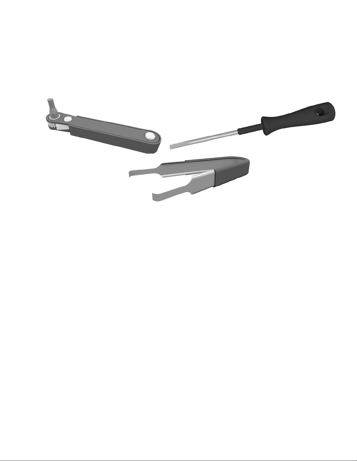
1.4 - Additional Tools
The following additional tools are needed to complete installing and commissioning the
SolarCity H6 inverter:
•Allen wrench, ratchet type, with 5mm bit (such as the Great Neck 51063, Neiko Tools
03044A, or the Husky Tools 66604). See
Figure 1-3
, below.
•1/8” flat screwdriver with a long shank. See
Figure 1-3
, below.
•Chip puller to replace the ZigBee chip.
7
Copyright 2017 SolarCity Corporation. All rights reserved.
Chapter 1 - Welcome
•Mounting screws, as follows:
-16” or 24” wood studs: 6mm x 89mm (1/4” x 3 ½” lag screws)
-Plywood panel (minimum 20mm / 3/4” thick): 6mm x 25mm (1/4” x 1” wood screws)
-16” steel studs: 6mm (1/4”) self-drilling sheet metal screws
-Masonry: 6mm x 32mm (1/4” x 1-1/4”) concrete anchor screws
Figure 1-3: Ratchet wrench, long-shank screwdriver, and chip puller
1.5 - About This Manual
This section describes the formatting conventions and information contained in this manual.
1.5.1 - Formatting Conventions
This manual uses several formatting conventions to present information of special
importance.
Lists of items, points to consider, or procedures that do not need to be performed in a
specific order appear in bullet format:
•Item 1
•Item 2
Procedures that must be followed in a specific order appear in numbered steps:
1. Perform this step first.
2. Perform this step second.
Interface elements such as document titles, fields, windows, tabs, buttons, commands,
options, and icons appear in bold text.

H6 Hybrid Inverter - Installation & Operation Guide
8Copyright 2017 SolarCity Corporation. All rights reserved.
Specific commands/values appear in standard Courier font. Sequences of commands
appear in the order in which you should execute them and include horizontal or vertical
spaces between commands.
1.5.2 - Safety Symbols
This manual also contains important safety information and instructions in specially
formatted callouts with accompanying graphic symbols:
This icon highlights equipment grounding conductor operations.
SHOCK HAZARD: SHOCK HAZARD WARNINGS ALTERT YOU TO THE
POSSIBILITY OF DEATH OR PERSONAL INJURY OR DEATH FROM
ELECTRICAL SHOCK IF THESE INSTRUCTIONS ARE NOT FOLLOWED.
WARNING: WARNINGS ALERT YOU TO THE POSSIBILITY OF DEATH OR
PERSONAL INJURY FROM CAUSES OTHER THAN ELECTRICAL SHOCK IF
THESE INSTRUCTIONS ARE NOT FOLLOWED.
HOT SURFACE: HOT SURFACE CALLOUTS ALERT YOU TO SURFACES THAT
COULD BECOME HOT ENOUGH TO POSE A BURN HAZARD DURING
NORMAL OPERATION.
CAUTION: CAUTIONS ALERT YOU TO THE POSSIBILITY OF EQUIPMENT OR
PROPERTY DAMAGE IF THESE INSTRUCTIONS ARE NOT FOLLOWED.
Note: Notes provide helpful information.

9
Copyright 2017 SolarCity Corporation. All rights reserved.
Chapter 1 - Welcome
1.5.3 - Layout
This guide contains the following chapters:
•Chapter 1 – Welcome: Introduces this guide and describes worker qualifications, package
contents, and tools, and provides references to additional documentation and resources.
See
“Welcome” on page 1
.
•Chapter 2 – Safety Instructions: Provides general safety instructions that must be
observed at all times. See
“Safety Instructions” on page 11
.
•Chapter 3 – Overview: Describes the SolarCity H6 inverter including dimensions,
clearances, mounting options, controls, connections, and external components/
accessories. See
“Overview” on page 17
.
•Chapter 4 – Installation: Describes installing the Inverter Mounting Bracket and then
hanging the SolarCity H6 inverter the bracket. See
“Installation” on page 47
.
•Chapter 5 – Electrical Connections: Describes making the electrical connections
between the SolarCity H6 inverter and the other components in the installation. See
“Electrical Connections” on page 55
.
•Chapter 6 – User Controls: Describes the LEDs, LCD display, and keyboard controls of the
SolarCity H6 inverter and describes the menu structure and user-controllable functions
of the inverter. See
“User Controls” on page 73
.
•Chapter 7 – Commissioning: Describes how to commission the SolarCity H6 inverter for
use. See
“Commissioning” on page 83
.
•Chapter 8 – Basic Operation: Covers routine procedures, such as powering the SolarCity
H6 inverter on and off and how power flows to and from the inverter under a variety of
operating conditions. See
“Basic Operation” on page 85
.
•Chapter 9 – Product Information: Lists the specifications, protection features,
standards, performance, and regulatory approvals that apply to the SolarCity H6 inverter.
See
“Product Information” on page 91
.
•Chapter 10 – Troubleshooting and Maintenance: Describes how to troubleshoot the
SolarCity H6 inverter and perform basic maintenance tasks. See
“Troubleshooting and
Maintenance” on page 103
.
•Appendix A – Glossary: Lists and defines the key terms and abbreviations used in this
guide. See
“Glossary” on page 123
.
•Appendix B - SMART RSD: Information and instructions for the Rapid Shutdown (RSD)
equipment. See
“SMART Rapid Shutdown Slave” on page 127
.

H6 Hybrid Inverter - Installation & Operation Guide
10 Copyright 2017 SolarCity Corporation. All rights reserved.
1.6 - Related Documentation
The following additional documentation is available for your SolarCity H6 inverter:
•H6 Datasheet
•SMART RSS Datasheet
•UL Certificate
•RGM Certificate
•FCC Certificate
These documents are available on the SolarCity Intranet (Grid).
1.7 - Additional Resources
Additional installer resources are available on the SolarCity Intranet (Grid).
1.8 - Technical Support
For technical and other support related to customer care, please contact Delta as follows:
15700 Don Julian Road
City of Industry, CA 91745
Support Email:
inverter.support@deltaww.com
Fax: 1-626-709-5896
Support Hotline: 1-877-442-4832 (toll free)
Support (International): 1-626-369-8019
Mondays to Fridays from 9:30am to 8:30pm Eastern time (except national and company
holidays)
Table of contents
Other SolarCity Inverter manuals


Popular Inverter manuals by other brands

Shindaiwa
Shindaiwa dga20e Owner's and operator's manual

Sumitomo
Sumitomo CAI Series Operation manual

Phoenix Contact
Phoenix Contact RAD-SOL-SET-24-100 user manual

Chyron
Chyron infinit! series Operation manual

Edwards Signaling
Edwards Signaling Adaptatone 5530M-485 Series installation instructions

EINHELL NEW GENERATION
EINHELL NEW GENERATION STE 5000D operating instructions

CPS
CPS SCA Series Installation and operation manual

SOLIS
SOLIS RHI-5G Series instruction manual

Telefunken
Telefunken TF-PI05 instruction manual

Grid Tie
Grid Tie 500W user manual

United Technologies
United Technologies Carrier Transicold 69UG15 Operation and service

Victron energy
Victron energy MultiPlus 12/3000/120 - 50 manual


