P/N 3100346 ISSUE 3
PAGE 3
CAUTIONCAUTION
CAUTIONCAUTION
CAUTION
During installation, care must be taken so that components
on the printed circuit board are not damaged.
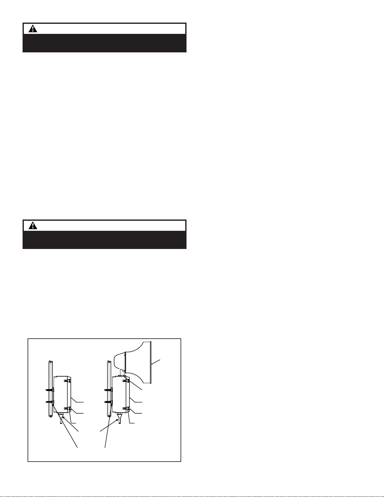
1. Mount Adaptatone as shown in Figure 3.
a. Flat Surface Mounting. Secure unit to
mountingsurface using the (4)mountingholes in
the mounting plate on the rear of the box. Use
the#10x3"(76mm)woodscrews(furnishedloose)
or other hardware (not supplied) suitable for the
mountingsurface.
b. Rigid Pipe Mounting. Loosenthe(4)coverscrews
from the signal box and lift off signal box cover.
NOTE: Cover screws are captive. Do not remove from
cover.
Removethe center knockoutin lower wallof box
and mount box to a 1/2" (12.7 mm) conduit pipe
using suitable connector.
2. Install wires through a knockout hole in the bottom
oftheboxfroma raceway that is, with itsconnections
tothe1/2"(12.7 mm)conduitknockouthole,approved
forthesame degree ofprotectionand enclosure type
needed by the application. Use the provided plastic
tie-wrap,onthebarrier to the electronics, to separate
incomingpower leads from signaland tone initiating
leads, per NEC (Figures 4, 5 and 6).
Figure 3. Adaptatone Mounting
WARNINGWARNING
WARNINGWARNING
WARNING
To prevent fire and shock, wire the Adaptatone only as
describedin thisinstallation instruction.
d. Connect incoming power to wire leads using a
butt splice or other method listed, certified, or
otherwise approved by local authorities. Leads
are black and white.
e. Optional. Connect external 24V DC battery (not
supplied) in series with separate diode assembly
part 2600010 (supplied) to TB1 terminals 3 and 4
on the main board as shown in Figures 4 and 5
and marked on the diode assembly.
NOTE: Terminal Block TB1 can be unplugged from the
main board to complete wiring as shown in
Figure 4.
4. Wire the 5532M series speaker/amplifier as follows
referring to Figures 6, 7 and 8:
a. Connect green and yellow striped earth-ground
wirestoearth-ground.
b. See Figure 8. Connect audio output (+) from the
main board of the tone generator to the AUD (+)
terminalonthe Speaker/Amplifier Audio Coupler
Board. Connect audio output (-) from the main
boardofthetonegeneratortotheAUD(-)terminal
on the Speaker/Amplifier Audio Coupler Board.
Use shielded cable and connect braid or drain to
earth-groundwirelead of 5540 Tone Generator.
c. Connect incoming power to wire leads using a
butt splice or other method listed, certified, or
otherwise approved by local authorities. Leads
are both black for -AQ and -N5 models and are
blackfor lineandwhiteforneutral for -Y6models.
e. Optional. Connect external 24V DC battery (not
supplied) in series with separate diode assembly
part 2600010 (supplied) to TB1 terminals 3 and 4
on the main board as shown in Figure 7 and
marked on the diode assembly.
NOTE: Terminal Block TB1 can be unplugged from the
main board to complete wiring as shown in
Figure 7.
5. Wire to the 5532B series speaker/amplifier as follows
and referring to Figures XX:
a. Connect green earth-ground wire of speaker/
amplifier and green and yellow striped earth-
groundwiresontone generator to earth-ground.
b. Connect audio output(+) from the mainboard of
thetonegeneratortothe ToneIn terminal 9 (+) in
the Speaker/Amplifier. Connect audio output (-)
fromthemainboard of the tone generatortothe
Tone In Termal 10 (-) in the Speaker/Amplifier.
d. For 5532B-AQ, 5532BDV2-AQ and 5532BHV-AQ
models, connect power source to the Speaker/
Amplifiers at TS2. Polarity must be observed for
DC models.
e. For 5532B-Y6, 5532BDV2-Y6, 5532BHV-Y6, and
5532B-N5models,connectincoming powertowire
leads from power supply. For -Y6 models using a
DC source, black wire is positive and white is
negative and polarity must be observed. For AC
source, black is line and white is neutral.
g. Optional. Wire 24V DC battery backup to TS1-1
and TS1-2 of the Speaker/Amplifier per Figure 18
andconnect 24V DC batterybackup in serieswith
diode assembly part 2600010 (supplied) to TB1
3. Wire the 5540M Series Tone Generator referring to
Figures 4 and 5 as follows:
a. Connect green and yellow-striped earth-ground
wirestoearth-ground.
b. Connect the RS485wires to terminals +TX/RXand
-TX/RX on the RS485 COMM board (Figure 5).
c. If using the optional MR201/C relay, connect the
relay to +RELAY and -RELAY on the RS485 COMM
board(Figure 5).
Speake
Large star nut to
adjust speaker
direction
Signal Box
(4) Cover
screws
Signal Box
(4) Cover
screws
(4) Collar
gaskets
(4) Collar
gaskets
Raceway and connections
(not supplied)
to the 1/2" (12.7 mm)
knockout hole
(4) #10 x 3" (76 mm)
screws or other hardware
suitable for the mounting surface