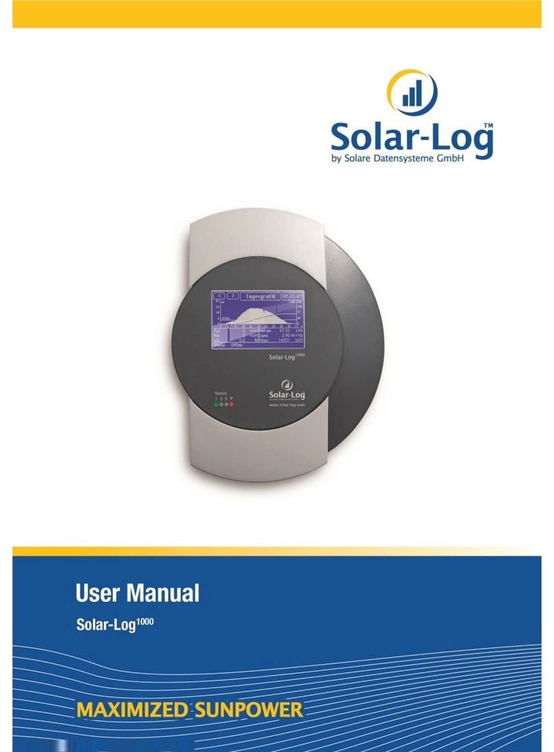
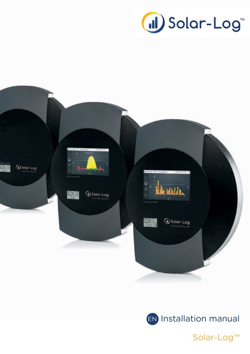
Solare Datensysteme Solar-Log 1000 User manual


Contents
Chapter 1: Introduction 9
1.1 Standard practice ........................................................................ 10
1.2 Safety Instructions ...................................................................... 10
1.3 Included in delivery ..................................................................... 11
Chapter 2: Installation 13
2.1 Connection options ..................................................................... 13
2.2 Connection to inverter ................................................................... 14
2.3 Terminal block connector ................................................................ 14
2.4 SM .................................................................................... 15
2.4.1 Note - PiggyBack mixed mode ............................................................ 15
2.4.2 Bluetooth Operation ...................................................................... 15
2.4.3 Special RS485 PiggyBack (Manufacturer: Solare Datensysteme Ltd.) .......................... 16
2.4.4 Important Notes for Installation ........................................................... 16
2.4.5 Installation ............................................................................... 17
2.4.5.1 Wiring scheme .............................................................................17
2.4.5.2 Control board without PiggyBack ...........................................................18
2.4.5.3 Control board with PiggyBack ...............................................................18
2.4.6 Original SM RS485/EI 485 PiggyBack (Manufacturer: SM ) .............................. 20
2.5 K CO - Powador / PVI-Blue Planet with RS485/EI 485 interface ....................... 20
2.5.1 Powador ................................................................................. 21
2.5.2 PVI-Blue Planet .......................................................................... 21
2.5.3 Wiring ................................................................................... 21
2.5.4 Terminal block - Powador - Models: ........................................................ 21
2.5.5 Terminal block - PVI-Blue Planet - Models: ................................................. 22
2.6 SolarMax - Series S, C and E with RS485/EI 485 interface ............................... 23
2.6.1 S and C Series ............................................................................ 23
2.6.2 Cx Series ................................................................................ 24
2.6.3 E Series ................................................................................. 24
2.6.4 Wiring ................................................................................... 24
2.7 Fronius - IG 15-60 (HV) and IG 35 + to IG 150+ with ComCard ......................... 25
2.7.1 Installation Fronius ComCard ............................................................. 25
2.7.2 Communication ddress .................................................................. 26
2.7.3 Wiring ................................................................................... 26
2.8 Danfoss – Inverters ..................................................................... 27
2.8.1 RS485/EI 485 interface .................................................................. 27
2.8.2 Wiring ................................................................................... 28
2.9 Mitsubishi with RS485/EI 485 interface ................................................. 29
2.9.1 Wiring ................................................................................... 29
2.10 Power-One/ urora ..................................................................... 29

2.10.1 Terminal block - Outdoor - Models: ........................................................ 30
2.11 Sunways – T/NT ...................................................................... 30
2.11.1 Terminal strip 750V - Models: ............................................................. 31
2.11.2 Terminal strip 850V - Models: ............................................................. 31
2.12 Vaillant - auroPOWER VPI/1 and VPI (RS485/EI 485) ................................. 31
2.12.1 Vaillant - auroPOWER VPI/1 ............................................................. 32
2.12.2 Vaillant – auroPOWER VPI ............................................................... 32
2.12.3 Wiring ................................................................................... 32
2.13 Solutronic (RS485/EI 485) ............................................................. 34
2.13.1 Wiring ................................................................................... 34
2.14 Schüco SGI Series (RS485/EI 485) ..................................................... 34
2.14.1 Wiring ................................................................................... 35
2.15 REFUSOL .............................................................................. 35
2.15.1 Wiring ................................................................................... 36
2.16 Kostal Pico / Solar-Fabrik Convert T (RS485/EI 485) ................................... 37
2.16.1 Wiring ................................................................................... 37
2.16.2 Multi-String technology ................................................................... 38
2.17 Mastervolt with (RS485/EI 485) ........................................................ 38
2.17.1 Wiring ................................................................................... 38
2.18 Suntension (Sunville) / Phoenixtec (RS485/EI 485) ..................................... 39
2.18.1 Wiring ................................................................................... 39
2.19 Diehl KO with RS485/EI 485 interface ............................................... 40
2.19.1 Wiring ................................................................................... 40
2.20 Connecting SolarLog1000 nalogue Modem Package ..................................... 41
2.20.1 Included in delivery: SolarLog1000 Modem Package ......................................... 42
2.21 Connecting the SolarLog1000 Mobile Package ............................................ 42
2.21.1 Included in delivery: SolarLog1000 Mobile Package .......................................... 42
2.22 Connecting the MT Sensor Box .......................................................... 42
2.22.1 ssembly ................................................................................ 43
2.22.2 Wiring ................................................................................... 43
2.22.3 Initial startup ............................................................................. 44
2.23 Connecting external electricity meters .................................................... 44
2.24 ttaching large displays .................................................................. 45
2.25 RS485/EI 485 wiring ................................................................... 45
2.26 S0 output wiring ......................................................................... 46
2.26.1 Current controlled S0 output .............................................................. 46
2.26.2 Contact controlled S0 output .............................................................. 46
2.26.3 Pulse factor .............................................................................. 46
2.27 Connecting Relays ....................................................................... 47
2.28 Connecting larm contacts .............................................................. 47
2.29 Connection to a PC / Network .......................................................... 48
4

Chapter 3: Manual 49
3.1 Touchscreen Display .................................................................... 49
3.1.1 Menu Structure Touchscreen Display ....................................................... 53
3.2 PC display .............................................................................. 54
3.2.1 Menu structure PC display ................................................................ 54
3.3 Initial startup ............................................................................ 54
3.3.1 Start configuration ........................................................................ 55
3.3.2 Inverter detection ........................................................................ 56
3.3.3 Inverter Configuration .................................................................... 57
3.4 Display menu navigation ................................................................. 58
3.4.1 Graphic ................................................................................. 58
3.4.1.1 Overview .................................................................................58
3.4.1.2 Day graphic ...............................................................................59
3.4.1.3 Month graphic .............................................................................62
3.4.1.4 Year graphic ...............................................................................63
3.4.1.5 Total graphic ..............................................................................64
3.4.2 Diagnosis ................................................................................ 64
3.4.2.1 Messages ..................................................................................64
3.4.2.2 Inverters event log .........................................................................65
3.4.2.3 larm contact (anti-theft) ...................................................................66
3.4.3 USB ..................................................................................... 66
3.4.3.1 Copy data .................................................................................66
3.4.3.2 Data backup ...............................................................................67
3.4.3.3 Firmware Update ..........................................................................68
3.4.4 Configuration ............................................................................ 68
3.4.4.1 Initial configuration ........................................................................68
3.4.4.2 Inverter detection ..........................................................................70
3.4.4.3 Inverter Configuration ......................................................................71
3.4.4.4 Network Settings ...........................................................................73
3.4.4.4.1 Dialogue 1 – Basic settings ................................................................73
3.4.4.4.2 Dialogue 2 – Network Router ..............................................................74
3.4.4.4.3 Dialogue 3 – nalogue Modem ............................................................74
3.4.4.4.4 Dialogue 4 – GPRS Modem ...............................................................75
3.4.5 Internet ................................................................................. 76
3.4.5.1 Basic settings ..............................................................................76
3.4.5.2 email/SMS ................................................................................76
3.4.5.3 Homepage ................................................................................76
3.4.6 dvanced ................................................................................ 77
3.4.6.1 Plant monitoring ...........................................................................77
3.4.6.2 Large display ..............................................................................77
3.4.6.3 RS485/EI 485 wireless package ............................................................78
3.4.7 Internal .................................................................................. 78
3.4.7.1 System ....................................................................................78
3.5 Configuration via PC .................................................................... 78
3.5.1 Basic Configuration ....................................................................... 79
5

3.5.1.1 L N - Network Settings ....................................................................79
3.5.1.1.1 Internet access ...........................................................................80
3.5.1.2 Plant groups ...............................................................................80
3.5.1.3 Inverters order .............................................................................81
3.5.1.4 Inverter ...................................................................................83
3.5.1.4.1 Connected generator power ................................................................83
3.5.1.4.2 Pac correction factor ......................................................................83
3.5.1.4.3 Product label .............................................................................84
3.5.1.4.4 Monitoring ...............................................................................84
3.5.1.4.5 Graphic Scaling ...........................................................................86
3.5.1.5 Forecast ...................................................................................86
3.5.1.5.1 Plant size ................................................................................87
3.5.1.5.2 Feed-in tariff .............................................................................87
3.5.1.5.3 nnual target .............................................................................87
3.5.1.5.4 Monthly share ............................................................................87
3.5.1.6 Graphic ...................................................................................87
3.5.2 dvanced ................................................................................ 88
3.5.2.1 Internet ...................................................................................88
3.5.2.2 email ......................................................................................89
3.5.2.3 SMS ......................................................................................91
3.5.2.4 Export ....................................................................................93
3.5.2.5 Fault ......................................................................................94
3.5.2.6 Status and error codes of SolarMax inverters .................................................95
3.5.3 Internal .................................................................................. 95
3.5.3.1 Backup ....................................................................................96
3.5.3.1.1 Backup - automatically ....................................................................96
3.5.3.1.2 Backup - manually ........................................................................96
3.5.3.1.3 Data correction ...........................................................................97
3.5.3.1.4 Data import of existing day's data ..........................................................97
3.5.3.2 System ....................................................................................98
3.5.3.2.1 Date/Time ...............................................................................99
3.5.3.2.2 dditional Password Question .............................................................99
3.5.3.3 Update ...................................................................................100
3.6 Homepage ............................................................................. 101
3.6.1 Free Homepage ......................................................................... 102
3.7 utomatic alerts ....................................................................... 102
3.7.1 Inverter failure message - email ........................................................... 102
3.7.2 Inverter failure message - SMS ........................................................... 102
3.7.3 Fault alert from performance monitoring - email ........................................... 102
3.7.4 Fault alert from performance monitoring - SMS ........................................... 103
3.7.5 Fault alert from status/error code monitoring - email ....................................... 103
3.7.6 Fault alert from status/error code monitoring - SMS ....................................... 103
3.7.7 larm notification via alarm contact - email ............................................... 103
3.7.8 larm notification via alarm contact – SMS ................................................ 103
3.7.9 Yield overview – email .................................................................. 104
3.7.10 Yield overview – SMS ................................................................... 104
6

3.8 Yield data .............................................................................. 104
3.8.1 PC Visualization ........................................................................ 105
3.8.1.1 Daily overview ............................................................................105
3.8.1.2 Monthly overview .........................................................................107
3.8.1.3 Yearly overview ...........................................................................108
3.8.1.4 Total overview ............................................................................109
3.9 Diagnosis .............................................................................. 111
3.9.1 Event log ............................................................................... 111
3.10 Dial-in using an nalogue Modem ...................................................... 113
3.11 Useful software ........................................................................ 116
3.11.1 Printing ................................................................................ 117
3.12 LED status display ..................................................................... 117
3.13 Reset button ........................................................................... 118
Chapter 4: Technical Data 119
4.1 Internet ports .......................................................................... 119
4.2 Timer ................................................................................. 120
4.3 ctivity log ............................................................................ 120
4.4 CE Declaration of Conformity ......................................................... 121
7


1Introduction
The SolarLog1000 represents the latest generation of the SolarLog series. Building on the web
technology of previous devices, there have been many wishes and suggestions consistently imple-
mented into this device.
The modern display with touchscreen and extensive connectivity options open up unprecedented
possibilities. The new case design is not only aesthetically pleasing but also very practical. This
allows all the cables to be kept hidden and at best completely invisible to the rear.
The SolarLog1000 is a device that can support a variety of inverters supported by its two data
interfaces. Environmental data such as sunlight radiation and temperatures, even wind measure-
ments can be recorded. The data can be loaded onto a USB stick and graphically analysed later
on a PC.
The integrated S0 pulse counter connection can connect digital electricity meters and hence meas-
ure electricity consumption. The SolarLog then automatically calculates an energy balance, offset-
ting its own electricity consumption.
Last but not least, the SolarLog1000 can attach large displays, through the S0 pulse output, or par-
allel to the inverter via the RS485/EI 485 interface.
The Bluetooth module is optionally available with the SolarLog1000 and can connect the latest
generation of SM inverters wirelessly.
ll these capabilities go to help ensure your photovoltaic system achieves the desired yield for a
long time and problems can be quickly identified and resolved.
In this sense, we wish you every success working with the SolarLog1000 with many profitable
and sunny days.
9

1 Introduction
1.1 Standard practice
The manual consists of 2 parts. First, the installation process is described, i.e. the assembly of the
SolarLogs and the wiring of the inverter to the SolarLog. Then follows the user's manual in
which the configuration and further operation will be described in detail.
Please get to know the device before installing anything. Especially during the initial
installation you should take some time to go through the manual - and not simply just "go
for it".
1.2 Safety Instructions
Read first prior to startup, the following safety instructions.
Our products leave the factory in perfect condition.
In order to maintain this condition, care must be taken in dealing with the equipment (transport,
storage, installation, startup, operation, maintenance, taking out of service). These safety instruc-
tions, model plates, labels and safety precautions must be observed, otherwise it can endanger
people's lives and the product itself, and other installations can be damaged.
These safety precautions apply in the Federal Republic of Germany. When used in other coun-
tries the relevant national regulations apply.
If the information with these safety precautions should not be sufficient, you can contact the
manufacturer at the given address at any time.
Please check the packaging and claim any damages immediately with the delivery company.
Make sure before turning on, that the power adapter has no damages. If in doubt, consult an
electrician or get in touch with the address at the end of this manual.
Before turning on, please make sure the voltage of the device is identical with the mains supply
in your country.
The device may only be operated with the included power adapter.
If the power adapter comes directly out of a cold environment to a warm environment, con-
densation may occur. Wait until the temperature compensation has taken place. To start the
device without the temperature compensation is life-threatening!
Repairs should only be performed by authorized personnel. Please contact the mentioned
address at end of the manual.
The power adapter should be checked regularly for damage. In the case of damage to the power
adapter, it needs to be immediately taken out of service and replaced.
10

The device is not suitable for outdoor use
Before cleaning: unplug the device! For cleaning use a gentle detergent with a damp cloth. Never
clean when dripping wet!
Other notes:
The SolarLog1000 operates on 12Volt DC (12VDC, max. 24VDC). Running the unit on a differ-
ent voltage will invalidate the warranty. Please use only the enclosed power adapter.
The SolarLog1000 has IP20 standard protection and is designed exclusively for installation in dry,
dust-free interiors.
The relay can be used with maximum 24VoltDC and loaded to 5 .
Before any cable connection between the SolarLog1000 and inverter is made, the inverters must
be without any power. That means the C side must first be separated, then the DC-side. Then
wait at least 5 minutes until the capacitors in the inverters have discharged.
1.3 Included in delivery
The SolarLog1000 is delivered with the following components:
1.SolarLog1000 – Basic Unit
2.12Volt Power adapter
3.Manual
4.Terminal block connectors for all connections: (except C N): 2x 3-pin, 1x 4-pin, 2x 6-pin
5.4x wall plugs (dowels) and screws for wall mounting
For connection to a PC or network you need a network cable (RJ45 C T5 or C T6) in the cor-
responding length.
Furthermore, you will need suitable cable material for the wiring of the inverters to each other.
Optionally available are suitable, prefabricated cable-sets for the respective inverter manufactur-
ers. The cables have a length of 3m.
11


2Installation
he installation of the SolarLog1000 must take place indoors and protected from dust. For
outdoor and dusty environments, the SolarLog needs to have appropriate protective hous-
ing.
T
The assembly is via 4 mounting points on the rear of the housing. This requires the removal
of the two housing shells top and bottom.
2.1 Connection options
The SolarLog1000 has extensive connections at the housing bottom and top.
Bottom:
Relay Relay, for switching external signals. For example rotating flashing beacon/light, etc.
RS485- First RS485/EI 485 interface. Connection to inverter, Sensor Box or large display
(inactive, when the optional Bluetooth interface is in use)
RS485/RS422-
B
Second RS485 interface (RS422 for Fronius/Phoenixtec). Connection to inverter,
Sensor Box or large display
Power 12V 12 Volt DC voltage input (max. 24VDC)
Network Ethernet network interface, 10/100 MBit
RS232/EI 232 RS232/EI 232 Modem Interface Connecting an analogue or GPRS Modem
Top side:
S0 In/Out S0 pulse input for connection to external electricity meter. S0 pulse output for connec-
tion to external large display
13

2 Installation
larm Contact loop for connection to anti-theft device. With optical cables transfers up to
5km.
C N C N bus, for future extensions. Currently unused. No terminal strip is included for
this socket.
USB USB host connection. Suitable for USB sticks up to 2GByte capacity (Warning: Not
suitable for connecting to PCs!)
Reset Reset button. Multi-function: 1. Restart SolarLog, 2. Reset to factory settings
2.2 Connection to inverter
Since the SolarLog1000 communicates directly with each inverter, the appropriate data cable is
required. For the connection of SolarLog1000 to the first inverter there are green terminal block
connectors.
Note: pre-assembled cable sets, suitable for your inverter, are available as accessories.
Since each inverter manufacturer uses different wiring and connections, you must have the relev-
ant data cable connected correctly. The following chapters describe the manufacturer supported
connection configurations.
Note: It is essential that you follow the instructions from the manufacturer for connecting the
data cables. These instructions can be taken from the appropriate manufacturer's documentation.
2.3 Terminal block connector
The SolarLog1000 has 2 RS485/EI 485 interfaces, each marked by " " and "B". The "B" inter-
face can also be used as a RS422 interface (for Fronius/Phoenixtec inverters).
RS485 : 4-pin green connector
1 4
RS485/RS422-B: 6-pin green connector
1 4 6
The numbering of the connecting plugs are from left to right, from 1 to 4 and 6.
14

The assignment of the connectors are as follows:
Pin RS485- RS485-B RS422 (for Fronius/Phoenixtec)
1 Data+ Data+ T/RX+
2 12V 12V 12V
3 Earth Earth Earth
4 Data- Data- T/RX-
5 R/TX+
6 R/TX-
Note: he term "data+" / "data-" is manufacturer specific. Sometimes "A" and "B"
are used/described here, or other combinations. Please adhere exactly to the description in
this manual, otherwise the inverter will not be detected!
2.4 SMA
Please note: For SMA inverters there are
2 different connection options
, depending on which RS485-PiggyBack is built
into the inverter.
Careful! - different wiring!
Original SM RS485 PiggyBack: 3-pin Wiring
Special RS485 PiggyBack: 4-pin Wiring
Both PiggyBacks can be fully integrated and installed into all SM inverters of type "SunnyBoy"
(exception: SB3000/4000/5000TL-20 Next Generation) or of type "Sunny Mini Central".
Important note: Never open the casing of the inverter if it is live. Observe strictly the instruc-
tions in the SM manual.
2.4.1 ote - PiggyBack mixed mode
The special RS485 PiggyBack can also be used in mixed mode with the original SM PiggyBack
modules. They must also have a 4-wire cabling in place. However, never connect clamp 2 (yellow
SolarLog) with clamp 3 (inverter with Original-PiggyBack/Data Module)
2.4.2 Bluetooth Operation
Note:
1.The Bluetooth operation is only possible when the optional Bluetooth module is installed on
SolarLog1000.
15

2 Installation
2.Currently only inverters SM -SB3000/4000/5000-20 support wireless Bluetooth operation
(May 2009)
For the Bluetooth operation, there's no preparation necessary on the inverter. The SolarLog1000
currently can read a maximum of 7 Bluetooth SM inverters
The detection should take place in the same room as where the inverter is. This will stop detec-
tion failures due to lack of range. fterwards, you can then test the SolarLog even further away
from the inverter. Signal strength display is unfortunately not possible.
2.4.3 Special RS485 PiggyBack (Manufacturer: Solare Datensysteme Ltd.)
Note: Here a 4-pin wiring is needed!
The special PiggyBack is a simple RS485 interface converter without controller or without its
own "intelligence". Through the simple and robust design, disturbance behaviour on the inverter
is eliminated. When correctly installed and in compliance with the installation requirements, the
technical data and properties of the inverter remain unchanged. The PiggyBack is galvanically
isolated and has a 6.5 kV isolation protection. Each PiggyBack runs individually a complete func-
tional test on the SM Inverter.
Note: The Special PiggyBack may only be combined and operated with the SolarLog1000.
The Special RS485 Piggy-backs are compatible with inverters of type
−SB-SunnyBoy (but not to the SB-3000/4000/5000TL-20 NextGeneration, here the original
SM RS485 Data module must be used)
−SMC SunnyMiniCentral
−SWR inverter (built from 2001 onwards). Possibly the display needs to be dismantled to add-on
the PiggyBacks. This "space problem" exists also on the original SM PiggyBack.
Please check the completeness of the supplied accessories:
1x isolation tube for data cable
1x Jumper
1x screw connection/feed through Inverter-PG 16 (M22)
1x flat power distributor for connection to housing/earth
2.4.4 Important otes for Installation
For the fitting of PiggyBack interface cards, the inverter must be opened. This may only be car-
ried out by trained professionals. You should also read all the instructions of the available
inverter manual.
16

2.4.5 Installation
Work on the inverter must carried out exclusively with a separate power supply. First disconnect
the inverter on the C side, then from the DC side. Then wait 30 minutes until all the live parts
are discharged.
lso, please note that in the inverter and on the interface card are sensitive electronic compon-
ents which can be destroyed by static discharge.
2.4.5.1 Wiring scheme
Step 1
Insert first the PiggyBack on the control board in the inverter. Make sure the word "below" is
visible on the bottom left side of the control board (see Figure 2 below). Note: The lower pin
row must be aligned left.
17
SMA Inverter 2SMA Inverter 1 SMA-Inverter x
SolarLog
Jumper
set
4-wire, shielded
Ca le
Insulating
tu e
Special
PiggyBack

2 Installation
2.4.5.2 Control board without PiggyBack
2.4.5.3 Control board with PiggyBack
Step 2
Now the individual inverters must be wired to one another. You need a 4-pin, shielded data cable
(e.g. 25m ring, Solare Datensysteme order no. 220014). Connect each of the 4 contacts (2,3,5,7)
on the terminal block of inverter 1 to inverter 2 and inverter to 3, etc. until you have connected
all inverters.
18
This is
where the
PiggyBack is
attached
La el:
Below

In older SM inverters of type SWR there's possibly a 10-pin terminal block strip available. Con-
nect here also the contacts 2,3,5 and 7 and leave the others free.
Please make sure that the data cable in the interior of the inverter is fed through the silicone
insulation strips.
Step 3
terminating resistor has to be set on the last inverter. Set the jumper to the lowest position:
The middle and upper position must remain free!
Step 4
Now you need connect the first inverters per cable with the SolarLog.
For the connection of SolarLog with the first inverter you can use either a prefabricated data
cable (not included) or your own cable.
19
Terminal
lock strip
Contacts
2,3,5,7
Jumper set
( ottom)

2 Installation
Pull the exposed wires through the cable opening of the inverter and connect them
SolarLog Terminal strip in the inverter
White (1) 2
Yellow (2) 3
Green (3) 5
Brown (4) 7
Pull the data cable through the enclosed insulation tube. Connect terminal strip 5 of the inverter
with the accompanying flat pin on the inverter casing.
This completes the hardware installation. You can close the inverter and turn it on.
2.4.6 Original SMA RS485/EIA485 PiggyBack (Manufacturer: SMA)
Note: 3-pin
wiring
is required!
The installation is very detailed in the SM PiggyBack manual, enclosed with the interface board.
The wiring of the inverters with one another is described on page "6 from 8" under "Wiring a
SB/SWR via RS485 to a PC". Connect each individual inverter as in the SM manual with a
shielded 3-pin data cable.
Then you set jumper on the PiggyBack of the last inverter as shown on page "5 of 8" and "6
of 8" in the SM 's manual.
For the connection of the SolarLog with the first inverter you can use either a prefabricated data
cable (accessories not included) or your own cable.
Pull the exposed wires through the cable opening of the inverter and connect them
SolarLog Terminal strip in the inverter
White (1) 2
Green (3) 5
Brown (4) 7
Pull the data cable through the enclosed insulation tube. Connect terminal strip 5 of the inverter
with the accompanying flat pin on the inverter casing.
This completes the hardware installation. You can close the inverter and turn it on.
2.5 KACO - Powador / PVI-Blue Planet with RS485/EIA485 interface
Important note: Never open the casing of the inverter if it is live. Observe strictly the instruc-
tions in the K CO manual.
20
Other manuals for Solar-Log 1000
1
Table of contents
Other Solare Datensysteme Measuring Instrument manuals
Popular Measuring Instrument manuals by other brands
Endress+Hauser
Endress+Hauser Levelflex FMP56 Brief operating instructions
Notsi
Notsi DeltaPulse Treasure Finder PRO user manual

Blue-White
Blue-White F-420 Series installation instructions
Dakota Digital
Dakota Digital Odyssey ODYR-19-5 manual

Endress+Hauser
Endress+Hauser Tank Side Monitor NRF590 technical information

PCE Instruments
PCE Instruments PCE-PMI 3 Instruction
