SolarEdge Home EV User manual

Version 1.0, <Type -in Mon. Year> 1
Error! No text of specified style in document.
SolarEdge Home EV
Charger
Configuration Manual
Version 1.00

SolarEdge
EV Charger
Electric Vehicle Charging Station
Configuration manual V 1.00
Translation of the original instructions

Document:V 1.00
Document No.:
Pages: 34
© SolarEdge Technologies
Customer Support
SolarEdge Technologies https://www.solaredge.com/service/support
© KEBA 2021
Specifications are subject to change due to further technical developments. Details presented may be
subject to correction.
All rights reserved.
KEBA Energy Automation GmbH Reindlstraße 51, 4040 Linz, Austria, www.keba.com/emobility

EV Charger Table of contents
Configuration manual V1.00 3
© SolarEdge Technologies
Table of contents
1 Introduction ................................................................................................................ 4
1.1 Representation of safety instructions............................................................... 5
1.2 Purpose of the document................................................................................. 6
1.3 Requirements................................................................................................... 6
1.4 Warranty .......................................................................................................... 6
1.5 Notes on this document ................................................................................... 7
1.6 Further documentation..................................................................................... 8
2 System overview ........................................................................................................ 9
2.1 Network interfaces ........................................................................................... 9
2.2 Displays and signals ........................................................................................ 12
3 Configuration.............................................................................................................. 13
3.1 Connection panel ............................................................................................. 13
3.2 DIP switch settings........................................................................................... 13
4 Web interface.............................................................................................................. 15
4.1 Main menu ....................................................................................................... 16
4.2 User menu ....................................................................................................... 21
5 Functions .................................................................................................................... 23
5.1 RFID authorization ........................................................................................... 23
6 Maintenance................................................................................................................ 28
6.1 Diagnosis and troubleshooting......................................................................... 28
6.2 Software update............................................................................................... 28
7 Support........................................................................................................................ 31
Index ............................................................................................................................ 32

EV ChargerIntroduction
Configuration manual V1.00
4
© SolarEdge Technologies
1 Introduction
This document refers to the following devices:
● SolarEdge Home EV Charger with software version 1.12.1
The device variant can be determined by the product designation on the type
plate. The software version can be read out via the web interface. For more
information, see the "Operating instructions".
The pictured devices used in this manual are visual examples. The figures
and explanations contained in this manual refer to a typical device design.
The devices used by you may differ in their appearance.

EV Charger Introduction
Configuration manual V1.00 5
© SolarEdge Technologies
1.1 Representation of safety instructions
At various points in this manual, you will see notes and precautionary warn-
ings regarding possible hazards. The symbols used have the following
meaning:
DANGER!
indicates an imminently hazardous situation, which will result in death or se-
rious bodily injury if the corresponding precautions are not taken.
WARNING!
indicates a potentially hazardous situation, which can result in death or seri-
ous bodily injury if the corresponding precautions are not taken.
CAUTION!
means that if the corresponding safety measures are not taken, a potentially
hazardous situation can occur that may result in slight bodily injury.
Caution
means that damage to property can occur if the corresponding safety mea-
sures are not taken.
ESD
This symbol reminds you of the possible consequences of touching electro-
statically sensitive components.
Information
Identifies practical tips and useful information. No information that warns
about potentially dangerous or harmful functions is contained.
EV ChargerIntroduction
Configuration manual V1.00
6
© SolarEdge Technologies
1.2 Purpose of the document
This document describes the configuration of the advanced features of So-
larEdge Home EV Charger after it has been installed. This includes, among
other things, the description of the settings in the web interface.
This document is an extension to the supplied manuals of SolarEdge Home
EV Charger.
You must comply with all instructions and safety instructions in the
supplied manuals!
1.3 Requirements
This document contains information for persons with the following require-
ments:
Target group Required knowledge and abilities
Electrician
Person who, due to his or her special training, expertise and experi-
ence as well as knowledge of current standards, is able to assess
the work performed and the possible hazards.
Knowledge of:
● current valid safety information,
● the mode of operation of the charging station,
● the displays and operating elements of the charging station,
● basics of network technology,
● basics of IT,
● diagnostic options,
● systematic fault analysis and rectification,
● the setting options on the charging station.
1.4 Warranty
Only general maintenance work that is expressly permitted by SolarEdge
Technologies may be performed. Any other tampering to the device will re-
sult in a loss of the warranty claim.
WARNING!
Risk of electric shock and fire hazard!
After the front part has been opened, product safety can no longer be guar-
anteed.
Only those covers that are described in the procedure instructions are al-
lowed to be opened. If one of the covers is sealed by a lead seal, it is not
permitted to be opened by unauthorized persons. If the lead seal is broken,
the device loses its specific suitability for use and may no longer be put into
operation due to the resulting incorrect identifier.
EV Charger Introduction
Configuration manual V1.00 7
© SolarEdge Technologies
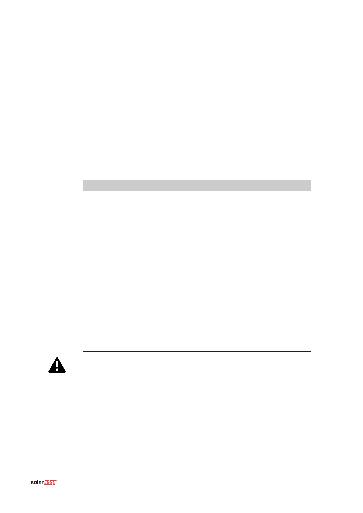
Fig.1-1: Screws on the front part
The front part 1 must not be opened. Opening the front part (4 Torx screws)
will break the manufacturer's seal and void the warranty claim. For a war-
ranty claim, there is a duty of proof of the customer that the defect – which
led to the defect of the device – already existed at the time of delivery. If the
manufacturer's seal is broken, this proof can no longer be provided, resulting
in expiration of the warranty claim.
A device with a broken manufacturer's seal or removed lead seal may no
longer be put into operation. The necessary steps must be taken for having
the charging station replaced or repaired by a specialist dealer or service
partner.
1.5 Notes on this document
The manual is part of the product. It is to be retained over the entire life cycle
of the product and should be forwarded to any subsequent owners or users
of the product.
The instructions contained in this manual must be followed precisely. Failure
to do so could result in the creation of potential sources of danger or the dis-
abling of safety devices. Apart from the safety instructions given in this man-
ual, the safety precautions and accident prevention measures appropriate to
the situation in question must also be observed.
1.5.1 Contents of the document
● Configuration of the advanced features of SolarEdge Home EV Charger
1.5.2 Not contained in this document
● Commissioning and deinstallation of the charging station
● Operating behavior of the charging station
● Operation of the charging station

EV ChargerIntroduction
Configuration manual V1.00
8
© SolarEdge Technologies
1.6 Further documentation
Manuals and additional information are available on our website:
www.solaredge.com/resource-library

EV Charger System overview
Configuration manual V1.00 9
© SolarEdge Technologies
2 System overview
SolarEdge Home EV Charger communicates with the SolarEdge Technolo-
gies OCPP backend. The charging station is equipped with different network
interfaces for these functions.
Fig.2-2: Example network setup
1 ... Local charging network 2 ... Router/Switch
3 ... Master charging station (x-series) 4 ... Client charging station (c-series)
5 ... Higher-level network/Internet 6 ... OCPP backend
The following chapters describe which network interfaces SolarEdge Home
EV Charger (master charging station) provides and how to set up a master/
client network.
2.1 Network interfaces
SolarEdge Home EV Charger provides the following network interfaces (e.g.
for connection to an OCPP backend, ...):
● LAN
● WLAN (optional)
● WLAN access point (optional)
Client charging stations can only be connected via LAN to SolarEdge Home
EV Charger (master charging station).

EV ChargerSystem overview
Configuration manual V1.00
10
© SolarEdge Technologies
2.1.1 LAN
SolarEdge Home EV Charger can be connected to a router via the inte-
grated LAN interface. The router establishes a connection to an OCPP back-
end via internet.
1 ... SolarEdge Home EV Charger 2 ... Router
3 ... Internet 4 ... OCPP backend
Connection: Ethernet1 connection (LSA+®)
Via the LAN interface, SolarEdge Home EV Charger can also be connected
to other charging stations, allowing to implement a charging network.
Information
The Ethernet1 connector X4 (LSA+®) and the Ethernet2 connector X3
(RJ45) are connected in parallel on the PCB and cannot be used at the
same time. The unused connection must be disconnected if necessary (e.g.
during servicing).
The Ethernet1 connection X4 is designed as a terminal block in LSA+® tech-
nology. It is recommended to implement hard-wired communication (e.g. for
SmartHome or a charging network) at the LSA+® connection.
2.1.2 WLAN (optional)
SolarEdge Home EV Charger can be connected to a router via the inte-
grated WLAN interface. If the router is connected to the Internet, a connec-
tion to an OCPP backend can be made.

EV Charger System overview
Configuration manual V1.00 11
© SolarEdge Technologies
1 ... SolarEdge Home EV Charger 2 ... Router
3 ... Internet 4 ... OCPP backend
The technical data of the WLAN module can be found in the "Installation
Manual".
Information
Only a charging station that is operated as a single charging station can be
connected to the router via WLAN. A charging station that is part of a
charging network (master/client network) must always be connected to the
router via LAN.

EV ChargerSystem overview
Configuration manual V1.00
12
© SolarEdge Technologies
2.1.3 WLAN Access Point (Hotspot) (optional)
SolarEdge Home EV Charger can be connected to a mobile device via the
integrated WLAN access point. With the mobile device, the web interface
can be easily accessed and the configuration of the charging station can be
performed.
1 ... SolarEdge Home EV Charger
The access data and the IP address of the WLAN access point are listed on
the configuration label. The configuration label is in a pouch which is en-
closed with the mounting material.
The following steps are necessary to perform the configuration via a mobile
device:
1) Connect a mobile device to the WLAN access point.
2) Access the IP address of the WLAN access point in a web browser on
the mobile device.
3) Perform configuration via the web interface, see 4 Web interface.
2.2 Displays and signals
The display on the front of the charging station provides information about
which communication connection is established.
Display Description
blue | blue | blue | blue
Communication is possible throughout the network.
The master charging station and the OCPP backend are reach-
able.
blue | blue | blue | -
Communication between master and client charging stations is
possible.
The OCPP backend is not reachable or missing.
- | blue | blue | -
Communication between master and client charging stations is
not possible.
The OCPP backend is not reachable.
EV Charger Configuration
Configuration manual V1.00 13
© SolarEdge Technologies
3 Configuration
This chapter describes the necessary configuration for the correct operation
of the charging stations. The following steps are necessary for this:
● Set the DIP switch on the charging station
● Configuration (via the web interface or via USB stick)
Depending on the network configuration, activation of the DHCP server on
the master charging station may be necessary.
3.1 Connection panel
In the connection panel of the charging station are important interfaces and
controls for the configuration of the charging station. To access, the housing
cover and the connection panel cover must be removed. The description of
removing the covers and the connection panel can be found in the "Installa-
tion Manual".
3.2 DIP switch settings
This DIP switch setting must be made for each master and client charging
station to enable charging station communication.
Caution
Possible damage to the DIP switches!
The DIP switches are rocker switches and not slider switches. The DIP
switches must be pressed and must never be slid.
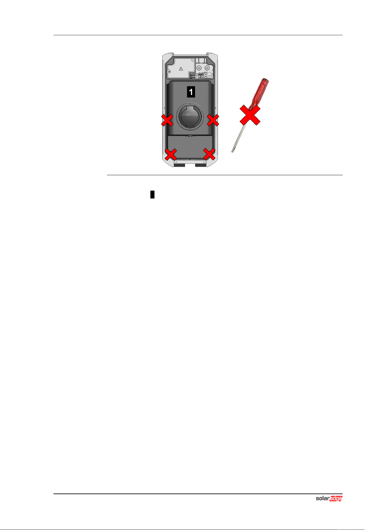
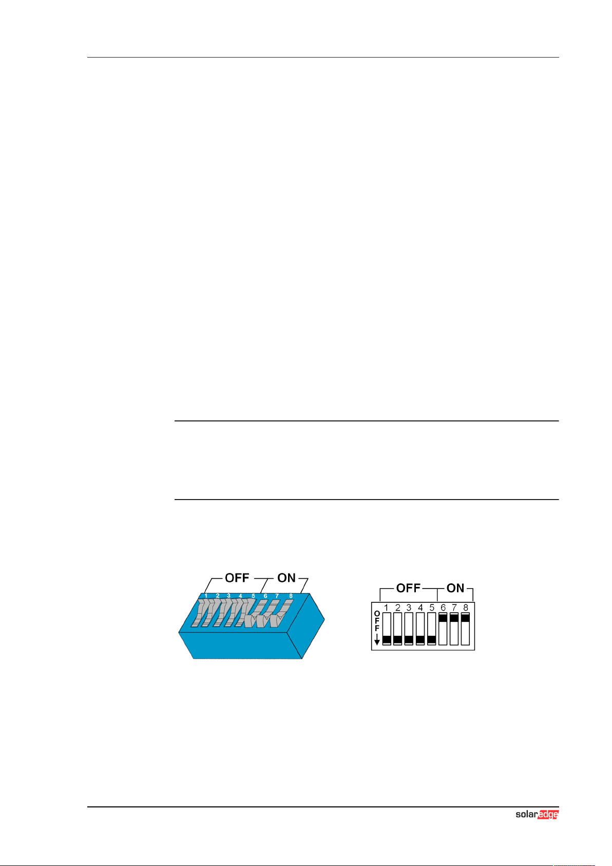
ON/OFF position of the rocker switches
The illustration shows the position of the rocker switches for the setting ON
and OFF
The DIP switches are located under the connection panel cover. The follow-
ing figure shows only the affected DIP switches, others are not shown. The
following setting must be made on the DIP switch DSW2:

EV ChargerConfiguration
Configuration manual V1.00
14
© SolarEdge Technologies
Activation of communication - DSW2.5
Function Figure
Activation of communication
This DIP switch setting must be made for each master and
client charging station to enable charging station communica-
tion.
Information
Changes to the DIP switch settings only become effective after a restart of
the charging station!
To restart, press the "Service button" until the first beep (approx. 1 second)
or switch off the charging station for a short time via the line circuit breaker.
EV Charger Web interface
Configuration manual V1.00 15
© SolarEdge Technologies
4 Web interface
The necessary settings (main menu "Configuration") for the communication
of the charging station are configured in the web interface. The configuration
for the entire charging network is done via the master charging station.
A network connection is required to access the web interface of the master
charging station. The network connection can be made via LAN, WLAN,
WLAN access point or mobile communications (e.g. with PC or mobile termi-
nal).
The master charging station web interface can be accessed by entering the
IP address of the master charging station in a web browser.
The IP address of the master charging station is determined differently de-
pending on the connection type.
WLAN access point The IP address of the WLAN access point is printed on the con-
figuration label.
Router with integrated
DHCP server
The charging station automatically receives an IP address via
the DHCP server of the router. The IP address is displayed on
the charging station display when the charging station is
(re)started. The IP address can also be determined via the
router.
Master charging station
with local DHCP server
The local DHCP server has been activated for the master
charging station, which automatically gives the master charging
station the following IP address: 192.168.42.1
The DHCP server of the charging station is deactivated in the
delivery state and can be activated via the configuration in the
web interface.
A login is required to use the web interface.
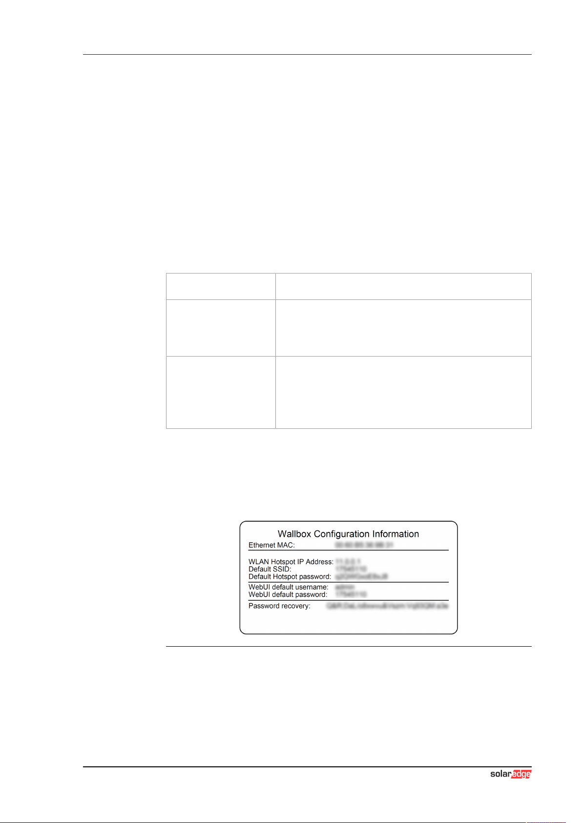
The login data for the first login in the web interface is printed on the configu-
ration label. The configuration label is in a pouch affixed to the installation
materials. For security reasons, change the password after the initial login.
In doing so, observe the password guidelines, refer to 4.2 User menu.
Fig.4-3: Configuration label
After successful login, the start page of the web interface opens.
The following chapters provide an overview of the possibilities of the web in-
terface. A detailed description of the individual configuration options can be
found directly in the web interface next to the respective configuration entry.
EV ChargerWeb interface
Configuration manual V1.00
16
© SolarEdge Technologies
The actual size of the web interface may differ depending on the device vari-
ant.
4.1 Main menu
The main menu is divided into the following areas:
● Status
● Charging Sessions
● RFID Cards
● Charging Network
● System
● Configuration
4.1.1 Status
This page is divided into the following sections:
Overview
Here, basic information about all charging stations in the charging network is
displayed (such as serial number, IP address, operating state, etc.).
When the respective IP address is clicked, a new browser window displays
information about the charging, such as total energy, energy of a charging
session, power, voltage, current, status and event log. The scope of the dis-
played information is variant-dependent.
An "Actions" button is located next to each listed charging station. When the
button is clicked, the following functions are available:
Start Charging
Authorizes a charging session without an RFID card having to
be held before the sensor. This function is only available with
the authorization function enabled.
Stop Charging Ends the active charging session.
Restart Restarts the charging station.
Unlock
Unlocks the charging plug on the charging station (not for the
vehicle). For an active charging session, the charging session is
ended first and then the charging plug is unlocked.
Network Connection
Here, information about the network interfaces (LAN, mobile communica-
tions, WLAN and WLAN Access Point) of the master charging station is dis-
played.
Backend
Information about the OCPP backend (such as connection status and ad-
dress) is displayed here.

EV Charger Web interface
Configuration manual V1.00 17
© SolarEdge Technologies
4.1.2 Charging Sessions
This page displays details about the last 200 charging sessions. The "Ex-
port" button lets you export the charging sessions of the last 90 days as a
*.csv file.
A currently active charging session is displayed with the "PWMCharging"
status. Various filter functions let you search for certain charging sessions.
For example, you can filter for charging sessions that have a certain start
date or for which a certain RFID card was used.
4.1.3 RFID Cards
This page provides an overview of all stored RFID cards including their au-
thorizations. RFID cards can be taught-in, edited and deleted. RFID cards
can also be exported and imported as *.csv file.
4.1.4 Charging Network
The configuration of the charging network is carried out in this area.
The area offers the following options:
● Charging Network Parameters
● Chargepoint Parameters
Charging Network Parameters
The nominal supply voltage of the charging station is selected here and the
current limits for the charging network can be set.
With 1- or 2-phase charging vehicles, asymmetrical loading of the 3 phases
may occur. For such vehicles, the maximum charging current can be set in
this area. The charging station then detects whether the vehicle is a 1-, 2- or
3-phase charging vehicle and, if necessary, reduces the charging current to
the set value. If "0" is entered, this function is deactivated.
You can also set whether charging should continue after a power failure.
This setting is disabled by default.
Chargepoint Parameters
The connection type (1-phase or 3-phase) of the charging station is selected
here. For a 1-phase connection, the power cable wire that is used can also
be selected. For a charging network, the connection type of the slave charg-
ing stations can also be selected.
If a slave charging station loses the connection to the master charging sta-
tion, or if an error occurs at the master charging station, a specification can
be made for the maximum charging current at which charging is to be contin-
ued. If "0" is entered, the charging process is terminated in the event of an
error and the charging station is put into "out of operation" mode.

EV ChargerWeb interface
Configuration manual V1.00
18
© SolarEdge Technologies
4.1.5 System
Der Bereich bietet folgende Auswahlmöglichkeiten:
● Software Update
● Mobile Communications Info
● WLAN Access Point Info
● Logging
● DSW Settings
● Factory Data Reset
● Signed measurement data export
● Signed log data export
● Restart System
Software-Update
The currently installed software versions are displayed. A software update
can also be performed here.
Mobile Communications Info
Information about the mobile communications connection is displayed and
the connection to the selected mobile communications network can be
tested.
WLAN Access Point Info
The state of the WLAN access point (hotspot) is displayed.
Logging
The event log can be downloaded here.
DSW Settings
The DIP switch settings of each charging station in the charging network can
be displayed here.
Factory Data Reset
The "Reset" button resets the configuration of the charging station to the fac-
tory settings and all stored data (charging sessions, taught-in RFID cards,
web interface password, etc.) is deleted.
Signed measurement data export
The signed measurement data records can be exported here, which can be
used for billing charging sessions. This function is only available for device
variants with specific suitability.

EV Charger Web interface
Configuration manual V1.00 19
© SolarEdge Technologies
Signed log data export
The signed log data records containing an event log can be exported here.
This function is only available for device variants with specific suitability.
Restart System
The master charging station can be restarted using this button.
Certificates
For an encrypted connection, certificates can be imported in *.pfx format.
The connection to the web interface, OCPP backend and charging station
can be encrypted. The following certificates are available:
WebUI certificates
Certificate Purpose
Https WebUI Encrypted connection to the web interface
4.1.6 Configuration
The configuration of the charging station is carried out in this area.
Information
The DIP switch settings are independent of the web interface configuration
and cannot be overwritten by software.
The area offers the following options:
● Operating mode
● Device
● Charging network parameters
● Chargepoint parameters
● Network connection
● Certificates
● WLAN access point
● Proxy
● OCPP
● External TCP meter
● Display text
Information
The settings made are only applied after the "Apply" button has been
pressed.
Other manuals for Home EV
1
Table of contents
Other SolarEdge Batteries Charger manuals


Popular Batteries Charger manuals by other brands


Aervoe
Aervoe Sierra Wave operating instructions

Linear Technology
Linear Technology DC1484A-A manual

Chicago Electric
Chicago Electric 68859 Owner's manual & safety instructions

Smartgen
Smartgen BACMXX06 Series user manual

Stryker
Stryker SYSTEM G 7310-120-000 Instructions for use

BatteryMINDer
BatteryMINDer BatteryMINDer 36271 instruction manual