Solarsystems SSA-21 User manual

SSA Direct Thermal Collector Plate System Installation Manual

SSA DIRECT PHOTOVOLTAIC OPEN LOOP MANUAL
2
CONTENTS
1. Introduction
2. Basic Tools and Materials
3. Collector Location
4. Collector Orientation
5. Collector Dimensions
6. Mounting Hardware
7. Mounting Hardware Spacing
8. Pitch Pan
9. Array Mounting
10. Collector Piping
11. Collector Piping Detail
12. Piping Through Roof
13. Storage Tank Placement
14. Retrofit for DPV w/ Vacation Bypass
15. Open Loop Start-Up
16. Open Loop Maintenance
17. Direct PV System
18. Operational Checklist
19. Systems Parts List
20. Collector Yard Mount
3
3
4
4
5
5
9
9
10
11
11
12
13
13
14
14
15
16
16
17
17

SSA DIRECT PHOTOVOLTAIC OPEN LOOP MANUAL
3
1. INTRODUCTION
We at Solar Systems, LLC would like to extend our congratulations on your purchase of an Aquarius/Apollo
Thermal Water Heating System. Years of research and development backed by critical engineering have
brought you the finest solar products you can buy. Please take time to read this booklet thoroughly. Each
step is outlined completely and clarified by diagrams where necessary. All questions which arise from this
material should be answered before you attempt installation of the system. With a little thought and careful
planning, your Aquarius/Apollo System can be installed quickly and easily by yourself or by a qualified
plumber with a minimum of disruption to your business or home.
Please note, the Solar Systems Warranty will be valid and will be honored only if the thermal water
collector is installed by a Factory Certified Installer or a licensed plumber. (A list of Factory Certified
Installers is available at www.solarsystemsvi.com)
2. BASIC TOOLS AND MATERIALS
Electric Drill
Drill Index (w/ ½” and ¾” Wood Bits)
Hack Saw
Tubing Cutter
Tin Snips
16’ Tape Measure
24” Level
Flashlight
Extension Cord
Slip Joint Pliers
Needle Nose Pliers
Pipe Wretches, 10” & 14”
Open End Wrenches, 9/16 & 7/16
Screw Driver 6” Flat Blade
Screw Driver 6” Philips
Wire Stripper or Knife
Wire Cutters
Adjustable Wrenches 8”& 10
Torch and Striker
100 PSI Pressure Gage
Putty Knife
High Temperature Pipe Joint Compound
Wire Nuts or Connectors
Miscellaneous Copper Pipe & Fittings (3/4”)
Solder Flux
Emory Paper
Silicone Caulk and Roof Tar
½” I.D. Copper Tubing & Installation
Angle Iron
Threaded Rod, Nuts, & Washers
Stainless Screw Clamps
Thermal Adhesive
Aluminum Flashing Sheet
SSA DIRECT PHOTOVOLTAIC OPEN LOOP MANUAL
4
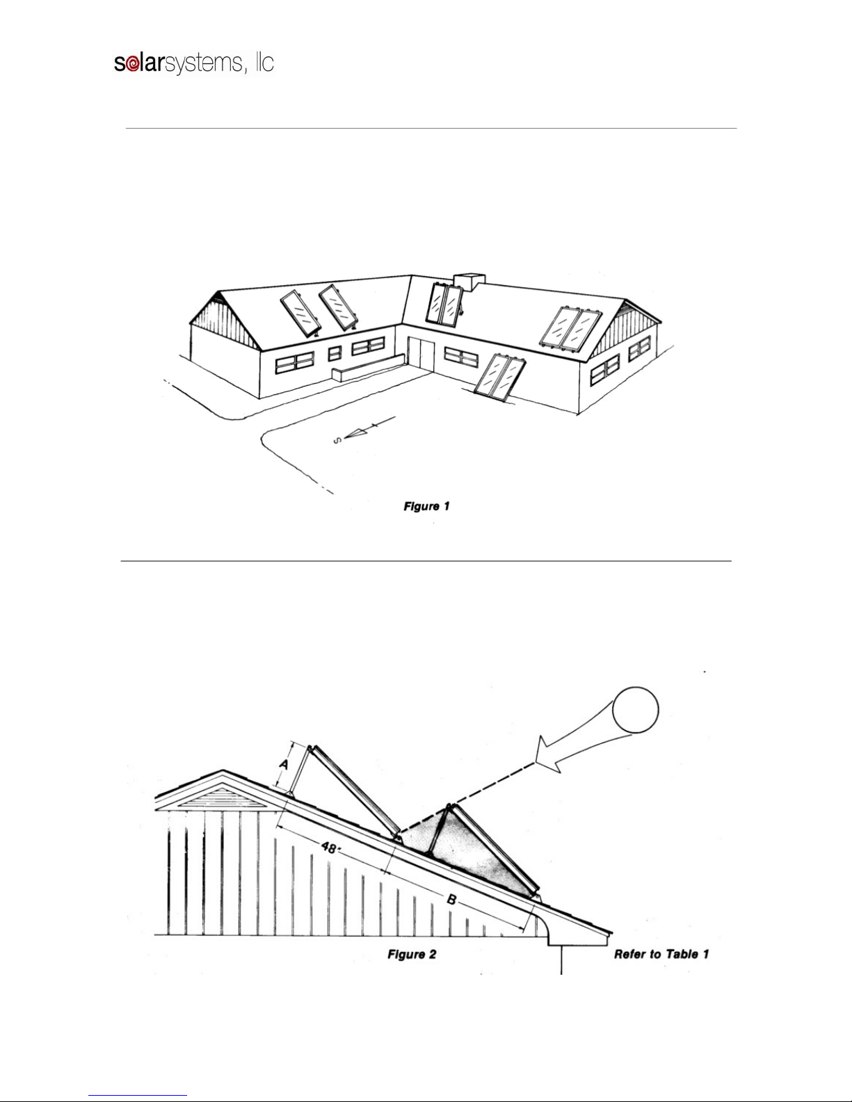
3. COLLECTOR LOCATION
Proper location and orientation of the solar
collectors is important for maximum system
efficiency. The collectors should be unshaded for
the middle six hours of the day in each month of the
year and should be located as close to the storage
tank as possible to minimize heat loss in the piping
runs. The best orientation is achieved
when the collectors are facing due south and tilted
at an angle from the horizontal of latitude. Figure 1
below shows many alternatives for collector
mounting.
4. COLLECTOR ORIENTATION
Proper tilt angle for solar collectors is your
location’s latitude. But due to our high irradiance
extreme variances can be successfully used. Refer to
3. and consult an installer for allowable instances.
Ambient temperatures are lower during the winter
and collector efficiency suffers slightly.
When collectors, using the tilt rack system, are
mounted one behind the other, they are spaced apart
so that in the morning and afternoon on December
21, when the sun is at its lowest altitude, the
collectors will not shade each other and cause
efficiency loss.

SSA DIRECT PHOTOVOLTAIC OPEN LOOP MANUAL
5
5. COLLECTOR DIMENSIONS
Collector Gross Area (ft2) Dimensions (in) Transparent Area (ft2) Weight (lb)
SSA-21 20.87 35
3/16 x 85 3/16 19.22 74
SSA-24 23.81 35
3/16 x 97 3/16 21.99 84
SSA-26 25.35 47
3/16 x 77 3/16 23.65 90
SSA-28 27.97 47
3/16 x 85 3/16 26.16 99
SSA-32 31.91 47
3/16 x 97 3/16 29.93 113
SSA-40 39.79 47
3/16 x 121 3/16 37.47 153
Tested: TUV (DIN 4757, RAPPERSWILL, ONORM M7714, FSEC, SRCC, Metropolitan Dade County, Miami Test Lab
Table 2. Collector Dimensions for SSA series
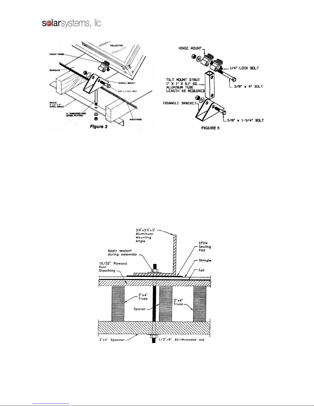
6. MOUNTING HARDWARE
Available with the System package is specially
designed mounting hardware to speed collector
installation. This hardware consists of four LOCK-
TIGHT hinge sets, four roof brackets, two rear
struts, and bolts (Figures 3, 4, and 5).
(a) After locating the mounting points from Table
1, the mounting bracket holes should be drilled.
(b) A heavy coating of sealant should be applied to
the bottom of the flashing plate, which should
fit flat against the roof. It is necessary for the
plate to slide under the above shingles to insure
proper drainage of water.
(c) The bottom of the roof bracket and the area
around the threaded rod should also be
thoroughly coated with tar sealant. When the
bracket is set in place, alignment with the
collector hinges is necessary before final
tightening of the nuts. This should be
completed before the sealant has time to set.
(d) The threaded rod is fastened through a 2’ x 6”
wood or 2” x 2” x ¼” steel angle bracket under
the roof as shown.
(e) The rear struts should be cut and drilled to
conform to Table 1. All bolts should be
tightened securely. A stainless steel washer
should be placed where the threaded rod passes
through the aluminum bracket.
It is very important that the penetrations through the
roof be well sealed. It should be carefully checked
that all bolts are coated with tar and that no leaks
are possible.
SSA DIRECT PHOTOVOLTAIC OPEN LOOP MANUAL
6
There are three acceptable ways to secure the
collector mounting brackets to the roof.
1. Spanner Mounting
2. Lag Bolt Mounting
3. J-Bolt Mounting
In spanner mounting after the brackets are positions
on the chalk line, a 3/8” hole is drilled between the
rafters. Aluminum flashing is positioned over the
hole where the top of the flashing is extended up
under the shingle above the 3/8” hole and extends
down over it. Caulk is applied between the flashing
and the roof. The bracket is then positioned over
the 3/8” hole using sealant between the bracket and
the flashing. A piece of 3/8” all-thread is then
inserted through the hole. A washer and nut secures
the all-thread to the bracket (be sure the seal
underneath the washer and on top of the nut). The
all-thread rod should extend about 4” below the roof
rafters. Drill a 3/8” hole in a 2 x 4 and insert the all-
thread rod through it. The 2 x 4 should span 2
rafters. With a washer and double bolt secure the
all-thread to the 2 x 4. Tighten down until the
bracket is tightly secured to the roof. Be careful not
to over-tighten and bell out the roof underneath the
bracket. (See Figure 6)
Figure 6. Spanner Mounting

SSA DIRECT PHOTOVOLTAIC OPEN LOOP MANUAL
7
In lag bolt mounting you must locate the center of
the rafters along the top and bottom chalk lines.
One method is to have one man on the roof and
another in the attic. Using a hammer the man on the
roof can tap the roof and determine where it is
denser sounding. The roof man can drill a pilot hole
while the attic man helps with distance corrections.
Then the attic man can call of the distance to the
next rafter while the roof man drills corresponding
pilot holes. Flashing the brackets is done as
previously described. Secure the brackets to the
roof using a 3/8” x 4” stainless lag screw, a flat
washer, and a lock washer (Figure 7).
Figure 7. Lag Bolt Mounting
SSA DIRECT PHOTOVOLTAIC OPEN LOOP MANUAL
8
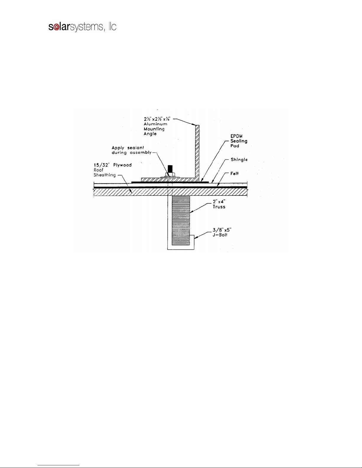
J-bolt mounting is done very similar to lag screw
mounting except instead of drilling into the center
of a rafter, a hole must be drilled directly beside a
rafter. The size of the hole must be slightly larger
than the bolt diameter. This is more easily
accomplished if the attic man would drill a pilot
hole through the roof alongside the chosen rafter.
Fit the bolt through the mounting brackets and insert
the bolt (J side first) through the hole in the roof.
Work the J underneath the rafter. Pull the J-bolt
snug against the rafter before tightening the nut.
Use double nuts or lock-washers to securely fasten
the mounting bracket to the J-bolt (Figure 8).
Figure 8. J-Bolt Mounting

SSA DIRECT PHOTOVOLTAIC OPEN LOOP MANUAL
9
7. MOUNTING HARDWARE SPACING
SSA-Series Center Line to Center Line (in.)
Model Size (ft) Outside Box Dim. (in.) SSA-MH SSA-FM SSA-RM
SSA-21 3 x 7 35.1875 x 85.1875 88.4375 88.9375 86.9375
SSA-24 3 x 8 35.1875 x 97.1875 100.4375 100.9375 98.9375
SSA-26 4 x 6.5 47.1875 x 77.1875 80.4375 80.9375 78.9375
SSA-28 4 x 7 47.1875 x 85.1875 88.4375 88.9375 86.9375
SSA-32 4 x 8 47.1875 x 97.1875 100.4375 100.9375 98.9375
SSA-40 4 x 10 47.1875 x 121.1875 124.4375 124.9375 122.9375
Table 3. Distance between centerlines of top and bottom mounts for all SSA Series Collectors
8. PITCH PAN
The pitch pan is necessary any time standing water
is encountered (Figure 9). The purpose is to provide
an adequate seal around any penetration in the roof.
(a) The pitch pan is placed in the proper position
and flat on the roof.
(b) Its flange is sealed with roofing felt and hot tar.
(c) The holes are sealed on the inside with roofing
tar to a sufficient level to insure a permanent
seal.
Figure 9

SSA DIRECT PHOTOVOLTAIC OPEN LOOP MANUAL
10
9. ARRAY MOUNTING ON TILE ROOFS
Tile roofs are a little more difficult to mount
solar collectors on but following this procedure will
render a leak free installation.
The solar panels are mounted on two rails
located at the top and bottom of the solar collectors.
The collectors are secured to the rails using the SSA
rack mount hardware (SSA-RM). The 1 5/8”
Aluminum unistrut rails are anchored to the roof by
using six or ten inch stainless steel 3/8” hanger
bolts. These bolts are lag screw on the bottom and
3/8 NPT thread on the top. A ten foot length of
unistrut should be anchored at three points, the
middle and both ends.
Procedure
a) Cut 12” x 12” square pieces of lead flashing.
b) Locate the roof rafters beneath the tile where
the hanger bolts will be attached. Drill a 3/8”
hole through the tile.
c) Slide the 12” x 12” lead flashing under the tile
located above the 3/8” hole, then drill through
the lead flashing into the hole.
d) Screw lag portion of the 3/8” hanger bolt into
the rafter.
e) Cut strips of the lead flashing about 1 ½” long
and wide enough that when you fold it into a
tube is slightly larger in diameter as the hanger
bolt.
f) Using an acid core solder, weld the seam of the
tube together.
g) Slip this tube over the top of the hanger bolt
protruding from the roof; solder it to the 12” x
12” lead flashing.
h) Thread down a stainless 3/8” nut to the bottom
of the thread and seal the top of lead tube to the
nut with a polybutalene caulk. Slip a 3/8”
stainless washer on top o the nut.
i) Place the 1 5/8” aluminum unistrut rail on the
hanger bolt and secure with another 3/8”
stainless washer and net.
The rail is now secured, weather tight to the tile
roof. Next, mount the Solar Systems solar collector
to the rail using the SSA rack mounts (SSA-RM).
See Figure 10.
Figure 10

SSA DIRECT PHOTOVOLTAIC OPEN LOOP MANUAL
11
10. COLLECTOR PIPING
The piping of the system should be considered
before a final decision is made on how the
collectors are mounted. Piping should be made of
copper tube of the type meeting local codes,
insulated with Armaflex or similar, and painted or
wrapped with aluminum tape where exposed to
ultraviolet radiation.
Care should be taken in the spacing of collectors as
attachment of piping is easiest with properly aligned
collectors. The collectors and piping to the storage
tank should be slightly sloped downward (3” in 8
feet) to allow draining in case of freezing
conditions. Soldered connections should be made
with 95/5 solder.
Figure 11 Figure 12
11. COLLECTOR PIPING DETAIL
The outlets of the collector are 1” copper pipe
nipples (Figure 13). They should be piped as shown
with provisions for an automatic air vent. This will
prevent air lock and subsequent loss of system
efficiency. The copper union makes attachment of
piping to collector easy. Teflon tape or high
temperature, high quality pipe sealant should be
used when making threaded connections.
The collector inlets should be piped similarly but
without the automatic air vent.
Figure 13
SSA DIRECT PHOTOVOLTAIC OPEN LOOP MANUAL
12
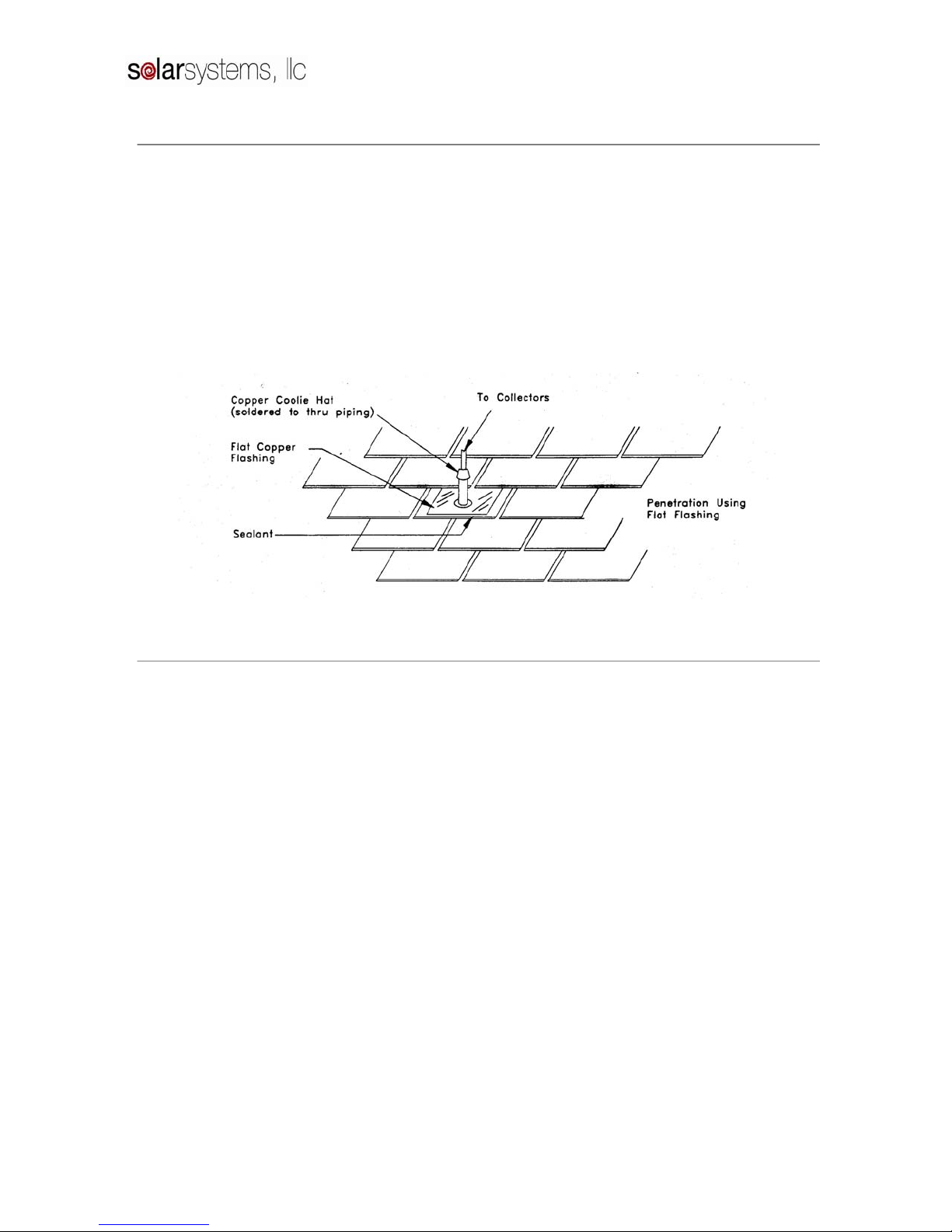
12. PIPING THROUGH THE ROOF
Piping through the roof should be weatherproofed
as shown in Figure 15.
(a) One inch holes are drilled through the roof on
the same plane as the supply and return header
nipples. Do not drill the hole above the supply
header of the collector. This will prevent the
collector from draining. Placing the hole below
the supply header is acceptable, but it is more
aesthetic if it is located on the same plane
(b) A copper flashing is placed around the hole
with its base cemented to the roof and its upper
edges slid under the adjoining shingle.
(c) The copper tube supply and return line is then
pushed up through the hole in the flashing.
(d) A “coolie cap” is then slid over the copper tube
till it meets the flashing. After piping to the
collectors is completed, the “coolie cap” is
soldered to the copper tube.
(e) Polybutalyne adhesive is then placed on the top
and bottom of the flashing, providing a
weatherproof seal. The sensor wire should also
be run through the return flashing.
Figure 15
13. STORAGE TANK PLACEMENT
To minimize expense and heat loss, the tank should
be placed near the collectors and central to points of
greatest water demand. It should be located in as
warm a spot as possible. It should be located with
adequate ventilation, with a minimum of 6-8 inches
of clearance and with ready access to controls and
serviceable parts.
Provision should be made to prevent water damage
in case of leakage. A catch pan with a minimum of
¾” drain line at least 2” in height may be installed
and pitched for proper drainage. Electrical service
of 240V should be available for the element and
110V for the pump if a non PV powered
recirculation pump is used.

SSA DIRECT PHOTOVOLTAIC OPEN LOOP MANUAL
13
14. RETROFIT FOR DPV W/ INSTALLATION BYPASS

SSA DIRECT PHOTOVOLTAIC OPEN LOOP MANUAL
14
15. OPEN LOOP START-UP
After visual inspection of the complete system, it is
ready for filling and pressure testing. All drain
valves should be closed, all other valves opened.
The air vent caps should be loosened two turns to
allow air to escape the system. The cold water inlet
valve should hen be opened slowly and system
checked for leaks as it fills. When the system is
completely full, indicated by water escaping from
the air vent when the valve is depressed it should be
pressure checked with normal pressure for 30
minutes. Final inspection should then be made and
power to the pump turned on. If the sun is shining
and the storage tank is cool, the pump should come
on and water should flow through the
collector. The first water through the collectors will
be very hot but should stabilize in about 15 minutes.
The return lines from the collectors should be hotter
than the inlet lines and the collector glass should be
slightly warmer than ambient temperature.
16. OPEN LOOP MAINTENANCE
Maintenance of an open loop system is
straightforward. The tank should be partially
drained every 6 months to allow minerals to be
removed preventing scale build up (this is
recommended for all water heaters). The wire
strainer should be cleaned at least once a year or
more often if harsh water conditions exist. The
power should be switched off, the piping drained,
and the screen removed and cleaned.
The collector glass should be kept clean for best
system performance. Rainwater will usually suffice
but a garden hose can be used during dry weather.
The air vent caps should be loosened two turns for
proper operation and best system performance.

SSA DIRECT PHOTOVOLTAIC OPEN LOOP MANUAL
15
17. DIRECT PV SYSTEM
The single photovoltaic module, attached to the top
of the solar collector (Figure 18) operates a
brushless 12 VAC or 24 VAC pump at a speed
relative to the amount of available sun. When
clouds pass over, the pumping operation slows to
allow the water to remain in the collector longer for
continued heating. When the sun goes down in the
evening the pumping action will stop.
The solar system is installed as per the open loop
installation manual. The photovoltaic module will
replace the differential control and sensors. Be sure
to mount the panels on the same plane as the solar
collector.
When wiring the photovoltaic module to the
circulating pump use 16 ga. stranded double exterior
PVC jacketed wire for lengths up to 85 feet for 10
and 25 watt modules. Use 14 gage for over 85 feet
for a module over 1.4 amps. When wiring the
module to the pump remember that the black wire is
always ground and the red wire is the hot wire. Do
not reverse the polarity.
Incorporated in the storage tank is a 240v back up
heating element. This should be wired by a licensed
electrician. The thermostat should be turned to a
low setting to allow the element to only operate
during periods of extended cloudiness.
Figure 18

SSA DIRECT PHOTOVOLTAIC OPEN LOOP MANUAL
16
18. OPERATIONAL CHECKLIST
Before the system is turned on, the piping and electrical systems should be evaluated to see if they match the
supplied drawings. If you are satisfied that the system is installed correctly, it should be filled and powered
according to the preceding instructions. When the system is in the operational mode, care should be taken to
check all piping for leaks and to make sure sufficient insulation has been used to provide maximum system
efficiency. All modes of operation should be checked by the installer to assure proper functioning under all
conditions.
TROUBLE SHOOTING GUIDE
Problems with systems usually fall under two categories: system leaks or lack of sufficient solar heated
water.
LEAKS
If leaks exist the system should be shut down for repairs. Make sure the electrical circuit to the controller is
off. Close off the cold water inlet or in case of a leak in the closed loop system, isolate as much of the
system as possible and then drain and repair the affected area.
There is a possibility that what appears to be leaks may be condensation on the pipes. Also water escaping
for the T & P valve may be an indication of proper function as they are designed to vent off excess
temperature and pressure.
INSUFFICIENT HOT WATER
If insufficient hot water is available a system malfunction may not be indicated. A low amount of solar
radiation or heavy water demand can be the cause.
If no excessive demands are put on the system and ample solar radiation is available, the system should
operate properly. The pump should run each sunny day until a full supply of hot water is stored. If the
pump does not run, there is a problem on the electrical end of the system. Either the pump, panel, or wiring
is malfunctioning.
OTHER PROBLEMS
A noisy pump is an indication of worn bearings obstruction or loss of prime. As a rule of thumb about 8 to
12 degrees should be expected as a normal gain across a collector in bright sun at proper flow rate.

SSA DIRECT PHOTOVOLTAIC OPEN LOOP MANUAL
17
19. SYSTEM PARTS LIST
Solar Collectors
Set of Mounting Hardware for each collector
Hot Water Storage Tank
Circulator Pump
Pump Flanges
Fluid circulation components (valves and fittings)
Installation Manual
20. COLLECTOR YARD MOUNT
When no sunny roof area is available or for “show” systems, the collectors can be mounted on the ground
as shown in Figure 19. The piping and control wiring to the tank should be insulated and buried. It is
important that the length of these piping runs be minimized.
Notes:
1. Front edge of collector should be 18” above ground
2. Use washers on all bolted wood connections
3. All pieces must be measured and cut to orient collector at latitude + 100– consult trigonometric
reference. Piping to collector may be buried.
Figure 19
This manual suits for next models
5
Table of contents
Popular Solar Panel manuals by other brands


LG
LG LG280N1C-G4 installation manual

XAG
XAG GNSS RTK Fix Station installation guide

BYD
BYD P6K Series INSTALLATION MANUAL AND USER MANUAL

Phaesun
Phaesun Sun Peak SPR Series Safety and installation manual

Solaria
Solaria PowerXT R-PD Series Safety, installation, and operation manual

Grape Solar
Grape Solar CS-S-160-DJ Safety and installation manual