Solartron Metrology MACH 1 Series Manual


Part No. 501414 Issue 9
The Mach 1 Series range of Transducer coil
assemblies are designed for protection against dust
and water, making them suitable for use in harsh
environments. Designed to be rugged and yet still
cost effective, these devices offer the Customer all
the attributes associated with L.V.D.T.’s. A variety
of combinations and accessories are available as
options.
1.1 Introduction
The Mach 1 range of transducers operate on the
L.V.D.T. principal, where movement of a core inside
the transducer body is detected by a differential
change in output on two secondary coils, the primary
coil(s) being energised by an appropriate AC signal.
With the core in a central position, the coupling from
the primary to each secondary is equal and opposite
and therefore cancel out, thus the resultant output
voltage is zero. As the core is displaced further into
one secondary, its voltage increases proportionally
and the other secondary voltage decreases hence
the output changes in magnitude and phase in
proportion to movement in either direction from null.
The red and white connections are in phase for
inward movement (ie. towards the cable end).
The output signal depends on both core movement
and energisation voltage and is expressed as a
sensitivity in mV output / V energising / mm travel.
1.2 Installation
L.V.D.T. transducers generally are a reliable and
proven technology that is well established in all areas
of manufacturing and control industries. The majority
of the associated problems experienced with their
application and use are totally avoidable, particularly
if sufficient thought is given during the initial design
stages of equipment, to the positioning and clamping
methods employed for these feedback elements.
L.V.D.T.’s being of inductive nature are susceptible to
some degree to the influence of magnetic fields and
therefore should be positioned well away from electric
motors, relays and permanent magnets, where this
is not possible then magnetic shielding should be
considered as an alternative.
Clamping of the coil assembly should be carefully
considered, some example methods are shown in
figure 1. Ideally the body of the transducers should
be clamped centrally in a pinch or yoke type clamp,
manufactured from a low conductivity, non-magnetic
material, if this is not possible then the introduction
of a non-metallic bush between body and clamp is a
preferred alternative.
2
1.0: General
1.0: General

Part No. 501414 Issue 9
Irrespective of clamping method care must be taken
not to over tighten retaining screws as distortion of
the body may prove damaging to the integrity of the
transducer and adversely affect the geometry of the
installation.
If the L.V.D.T. is to be mounted on equipment subject
to high ”g” then dependent on the direction of these
forces, it may be advantageous to consider end to
end clamping in preference to over body clamping.
The magnetic core supplied with each transducer
has been manufactured and heat treated to achieve
the optimum magnetic performance, any subsequent
handling of the core which results in stress being
imparted will render the calibration void, this includes
over tightening of the core during installation onto
its carrier. Hand tightening and retention by means
of a suitable thread locking anaerobic retainer is the
recommended procedure.
1.3. Cores
The standard core supplied with each transducer
incorporates an M4 x 0.7 x 12 mm deep female
thread at both ends for mounting onto a carrier, an
alternative 6-40 UNF female thread is available as a
standard option upon request.
1.4. Carriers
A standard length carrier is available for each model of
transducer, manufactured from 316 stainless steel and
incorporating an M4 x 0.7 x 10 mm long male thread
for attachment to the standard core and an M4 x 0.7 x
20 mm male thread for attachment to the fixture.
A 6-40 UNF thread option is also available.
1.5. Guided Carrier
1.5.1. MOUNTING Normal mounting methods apply
(see section 1.2. on Installation). Careful consideration
should be given to alignment, the carrier must be able
to move freely within the transducer core. Side force
should be kept to a minimal level.
1.5.2. MAINTENANCE: Check for free movement
of the carrier when in the vertical plane. Lubrication
is provided via an oilite bush which is impregnated
with molybdenum disulphide and in normal usage is
maintenance free.
3
1.0: General
1.0: General

Part No. 501414 Issue 9
1.6. Ball Tip
This option is for use with the Guided Carrier and is
attached via an adapter fitted to the threaded end of
the core carrier. Side forces which may exert undue
pressure and flex the carrier must be avoided.
1.7. Rod End Bearings
1.7.1. MOUNTING: With the exception of the
B100 the Transducer may be mounted in any axis;
it is recommended that the rear rod end bearing
(near cable exit) is mounted on the static component.
The B100, because of the increase in weight, may
exhibit bowing of the carrier and therefore mounting
in the horizontal plane should either be avoided or
additional support given to the body. This option is
used with the guided core.
1.7.2. MAINTENANCE: Rod end bearings are
supplied pre-lubricated with mineral oil; for higher
temperature applications the use of a molybdenum
disulphide impregnated oil is recommended and
your representative should be consulted about the
maximum temperature.
Periodic inspection of locking screws and nuts etc. is
advisable depending upon the Customer’s application.
Rod end bearings should be able to move freely and
have minimal side play.
1.8. Cable
5 kHz Version: Solartron Metrology cable is specially
manufactured to optimise performance with respect to
temperature, chemical resistance, flex life, abrasion
resistance and electrical performance. However, no
single cable design can fulfil every known requirement
and by taking a few simple precautions cable failure
can be avoided. In flexure conditions then a minimum
bend radius of 150 mm should be maintained. Avoid
contact with sharp edges and rough surfaces and
inspect at periodic intervals.
Excessive cable runs may alter the output
characteristics; if in doubt consult your representative.
2.5 kHz Version: The standard termination is by
7/0.125 P.T.F.E. insulated flying leads, capable of
withstanding the operating temperature of the L.V.D.T.
Routing of cables should be kept as smooth as pos-
sible avoiding burrs, sharp edges and excessive cable
loads.
4
1.0: General
1.0: General

Part No. 501414 Issue 9
1.9 Environmental
Operating Temperature Range A,B,K,L (types) *
-55 oC / +150 oC
Operating Temperature Range C,D,M,N (types) *
-55 oC / +200 oC
Storage Temperature Range A,B,K,L (types) *
-55 oC / +150 oC
Storage Temperature Range C,D,M,N (types) *
-55 oC / +200 oC
Conditions of high humidity and vibration should be
avoided.
1.10. Connectors
1.10.1. INTEGRAL: Transducers can be fitted with a
six pin connector, or a connector kit can be supplied
for fitting by the Customer. This option is not available
for Transducers fitted with rod end bearings, or radial
lead outlet. It is recommended to ensure satisfactory
operation that this option is Factory fitted.
1.10.2. IN-LINE: A five pin Din type connector can
be fitted to the lead, supplied loose or ordered sepa-
rately. If fitted to non-Solartron Metrology equipment,
careful observation of connections must be adhered
to as Solartron Metrology cannot be held responsible
for any damage which may result.
Figure 1 Examples of Clamping Methods
5
1.0: General
1.0: General
* An explanation of codes can be found on our ordering guide
or www.solartronmetrology.com

Part No. 501414 Issue 9
Figure 2 Plug Connections
6
1.0: General
1.0: General
Red Red/Yellow
Black/Yellow
Black
Green
Blue
Primary
Secondary
2.5kHz
Connect Blue to Green or Black to Red for differential
output.
Calibrated frequency, voltage load
2.5 kHz 3 volts rms 100 kW
Yellow/Red and Red are in phase for forward displace-
ment (toward cable end).
Note: Fit ”Quad Balance” resistor if supplied,
between Red/Blue or Black/Green, as directed, in
order to optimise linearity around null.
Green
Red
Blue
White
Yellow Shown
Termination
Side
1
2
3
4
5
5kHz
A
B
C
F
E
D
Shown Termination Side
Transducer Pin
Yellow A
Green B
Blue C
N/C D
Red E
White F
Figure 3 Connector Terminations - 5kHz
Note: Fit ”Quad Balance” resistor if supplied,
between Yellow/White or Yellow/Green, as directed,
in order to optimise linearity around null.
------------------------------------------------------------
Solartron Metrology, Bognor Regis, accepts no responsibility for damage when accessories are tted by the Customer. In the
event further information being required please contact your representative.
Other Solartron Metrology Transducer manuals
Popular Transducer manuals by other brands

Veris Industries
Veris Industries Hawkeye H720 installation guide
Enerdis
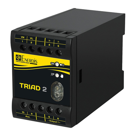
Enerdis TRIAD 2 User & installation manual

Setra Systems
Setra Systems 355X Series Operating & installation instructions

HBM
HBM P3MBP Mounting instructions

Emerson
Emerson Rosemount 3051 Reference manual

Flexim
Flexim PermaLok 2 INSTALLATION PROCEDURE
