Barksdale UTA 2 User manual
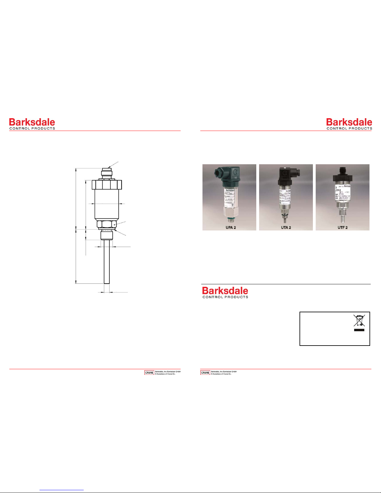
Dimensions in mm (inch) – Electronic temperature sensor UTF 2
Operating Instructions
Electronic Pressure and Temperature Transducers
UPA 2, UTA 2 and UTF 2
1Intended Applications ................................................................................................... 2
2Safety Instructions......................................................................................................... 2
3Standards ....................................................................................................................... 3
4Warranty/Guaranty......................................................................................................... 3
5Installation/Commissioning .......................................................................................... 3
6Maintenance/Cleaning ................................................................................................... 5
7Technical Data................................................................................................................ 5
Barksdale GmbH
Dorn-Assenheimer Straße 27
D-61203 Reichelsheim
Phone: +49 (6035) 949-0
Fax: +49 (6035) 949-111 and 949-113
Internet: www.barksdale.de
1
8
Art. no. 923-1910
Index: C, 15.08.2018
Specifications are subject to changes
without notice!
M12x1
A
B
ØG1/4"
L0
12 (0.47)
Ø6 (0.74)
56 (2.22)
70 (2.76)
Ø27 (1.06)
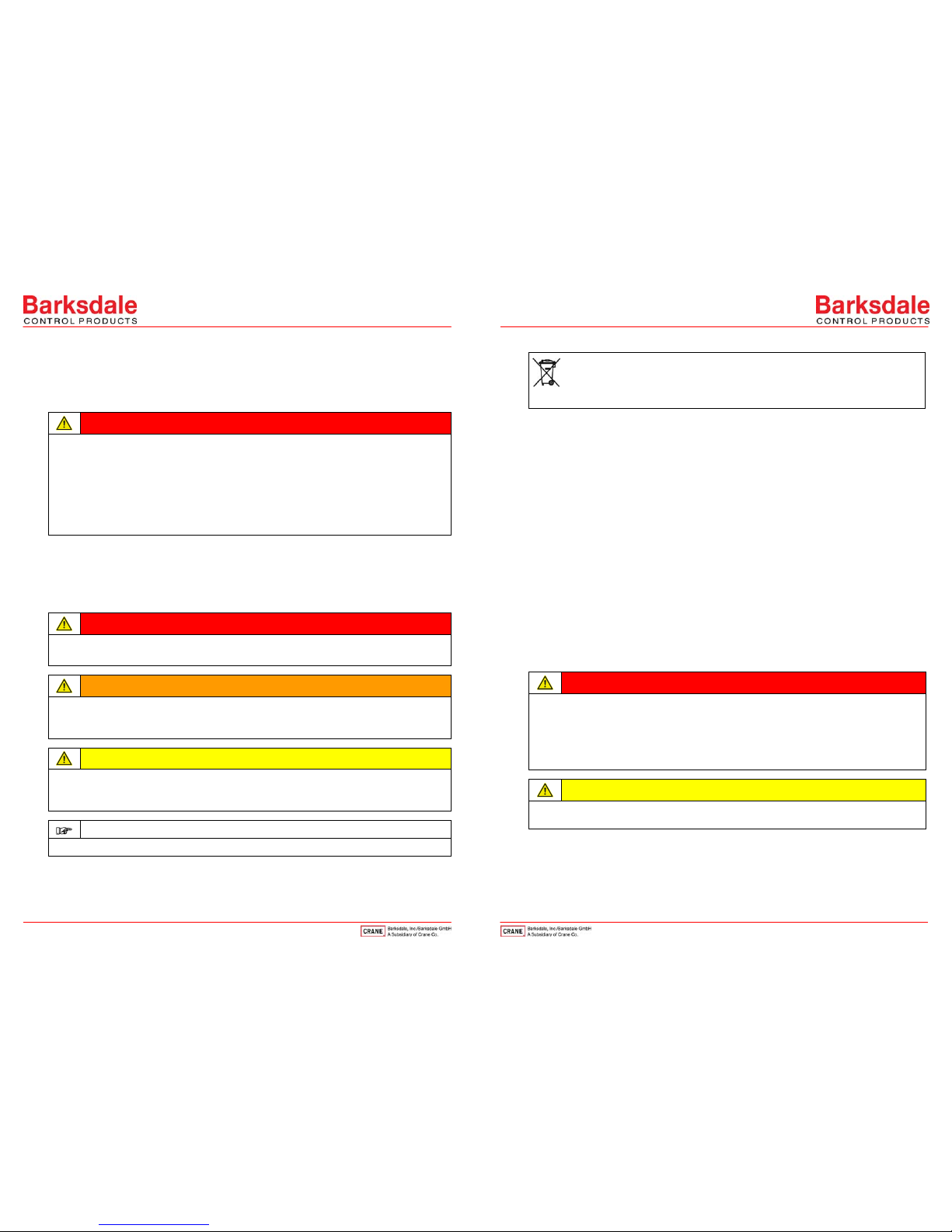
1 0B0B0B0BIntended Applications
The electronic pressure transducer UPA 2 serves for measuring a system pressure. The electronic
temperature transducer UTA 2 serves for measuring a system temperature. The pressure and
temperature sensors are equipped with analog outputs.
The temperature sensor UTF 2 provides the temperature value as PT100 signal.
DANGER
The electronic measuring devices must not be used for any other applications than those specified
in the instructions.
The temperatures must be within the specified ranges, the pressure values and the electrical rating
must not exceed the values specified.
Observe also the applicable national safety instructions for assembly, commissioning and
operation of the electronic measuring devices.
The electronic measuring devices are not designed to be used as the only safety relevant
elements according to PED 97/23/EC.
2 1B1B1B1BSafety Instructions
The safety instructions are intended to protect the user from dangerous situations and/or material
damage.
In the operating instructions the seriousness of the potential risk is designated by the following
signal words:
DANGER
Refers to imminent danger to men.
Nonobservance may result in fatal injuries.
WARNING
Refers to a recognizable danger.
Nonobservance may result in fatal injuries, and destroy the electronic measuring device or plant
parts.
CAUTION
Refers to a danger.
Nonobservance may result in light injuries and material damage to the electronic measuring device
and/or to the plant.
IMPORTANT
Refers to important information essential to the user.
Disposal
The electronic measuring device must be disposed of correctly in accordance with the
local regulations for electric/electronic equipment.
The electronic measuring devices must not be disposed of with the household garbage!
3 2B2B2B2BStandards
The standards applied during development, manufacture and configuration are listed in the CE
conformity and manufacturer's declaration.
4 3B3B3B3BWarranty/Guaranty
Warranty
Our scope of delivery and services is governed by the legal warranties and warranty periods.
Terms of guaranty
For the electronic pressure transducer UPA 2, the electronic temperature transducer UTA 2 and
the temperature sensor UTF 2 we grant a guarantee according to the legal regulations for
functioning and material in normal operating and maintenance conditions.
Loss of guaranty
The agreed guaranty period will expire in case of:
incorrect use,
incorrect installation or
incorrect handling or operation contrary to the provisions of these operating instructions.
No liability is assumed for any damage resulting therefrom, or any consequential damage.
5 4B4B4B4BInstallation/Commissioning
DANGER
Only install or remove the electronic measuring device when deenergized (electrically and
hydraulically/pneumatically).
Pressure connection and electrical connection must be carried out by trained or instructed
personnel according to state-of-the-art standards.
The electronic measuring devices may only be installed in systems in which the maximum
pressure Pmax or the maximum temperature Tmax is not exceeded (see type label).
CAUTION
Do not insert any objects into the pressure channel of the electronic pressure transducer!
The membrane on front-flush models must never be deformed!
3
2

Connecting the electronic measuring devices
CAUTION
The permissible overpressure must not be exceeded, not even in case of pressure peaks!
Install protection elements (e. g. damping screw)
The electronic measuring devices must be mounted at the bottom fitting with a size 19 wrench
(G ¼) or size 32 (G ½) and tightened to a torque of 45 Nm. The installation position is arbitrary.
CAUTION
Avoid electrostatic discharges!
Ground the housing
Electrical connection of the individual models (see type label) must be carried out according to the
chart below. The maximum power supply values are stated on the type label.
UPA 2
UTA 2
Current output
4... 20 mA
(two-wire system)
Voltage output
0... 10 V DC
(three-wire system)
Connection Plug Cable GL cable M12 Plug Cable GL cable M12
Supply (+) 1 brown white 1 1 1 brown blue 1 1
Supply (-) 2 white blue 1 2 2 blue blue 2 3
Signal (+) --- 3 white white 1 2
Signal (-) --- ---
Connection chart for temperature sensor UTF 2
PT100 Plug M12 x 1, 4-pin
6 5B5B5B5BMaintenance/Cleaning
The electronic measuring devices are calibrated in the factory and require not maintenance.
If faults occur which cannot be remedied please contact our local representative closest to you.
7 6B6B6B6BTechnical Data
IMPORTANT
see type label
Dimensions in mm (inch) – Electronic pressure transducer UPA 2 (G1/4")
A Process connection G1/4 acc. to DIN ISO 228-1
B Profile seal acc. to DIN 3869
C Cable gland Pg 11, clamping range Ø 6…8 mm
5
4
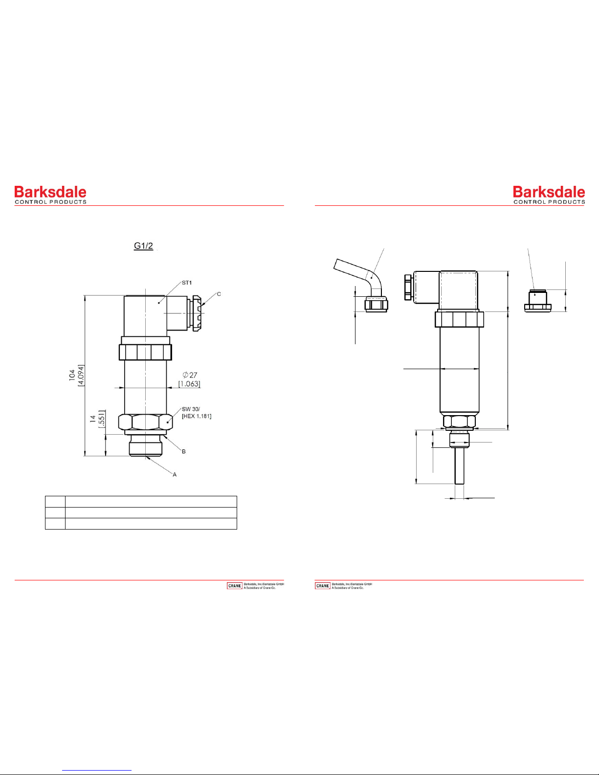
Dimensions in mm (inch) – Electronic pressure transducer UPA 2 (G1/2")
A Process connection G1/2 acc. to DIN ISO 228-1 flush at the front
B Profile seal acc. to DIN 3869
C Cable gland Pg 11, clamping range Ø 6…8 mm
Dimensions in mm (inch) – Electronic temperature transducer UTA 2
7
6
M12x1
~15 (0.59)
A
~28 (1.1)
~81.3 (3.20)
Ø18.9 (0.74)
G1/4"
L0
12 (0.47)
Ø6 (0.74)
11 (0.42)
Ø27 (1.06)
This manual suits for next models
2
Other Barksdale Transducer manuals

Popular Transducer manuals by other brands


Fishman
Fishman SBT-C installation guide

Rockford Fosgate
Rockford Fosgate IBeam IB-200 Installation & operation

GHM
GHM GREISINGER GMUD MP Series Mounting and operating manual

M-system
M-system LECA instruction manual

Novatech
Novatech Bitronics M660 user manual

SIAP+MICROS
SIAP+MICROS t027 TP200 User manual and maintenance