Solartron 1287 User manual

analytical
aRoxboro Group company
1287
ELECTROCHEMICAL INTERFACE
USER GUIDE
Part No. 12876000
Issue: AK
Date: August 2002
Solartron Analytical ©2001
Solartron Analytical UK
Unit B1 Armstrong Mall,
Southwood Business Park,
Farnborough,
Hampshire,
GU140NR
Tel: +44 (0) 1252 556 800
Fax: +44 (0) 1252 556 899
E-mail info @solartronanalvticaLcoro
E-mail for service issues
service ®solartronanalvtical.com
E-mail for customer support issues
support @solartronanaivtical.com
Solartron France
37 Rue Du Saule Trapu
91 882 Massy
Cedex
France
Tel: (33) 16953 6355
Fax: (33) 16013 3706
Solartron US
19408 Park Row, Suite 320
Houston, Texas, 77084
Tel: (1) 281-398-7890
Fax: (1)281-398-7891
Solartron Beijing Office
Room 1608
An Fu Building
No. 1Na FangZhuang
Zuo An Men Wai
Feng Tai District
Beijing 100078
People’s Republic of China
Tel: +86-10-67664948, 67664992
Fax: +86-10-67664905
Web: http://www.solartronanalytical.com
For details of our agents in other countries, please contact our Farnborough, UK, office.
Solartron pursues apolicy of continuous development and product improvement.
The specification in this document may therefore be changed without notice.
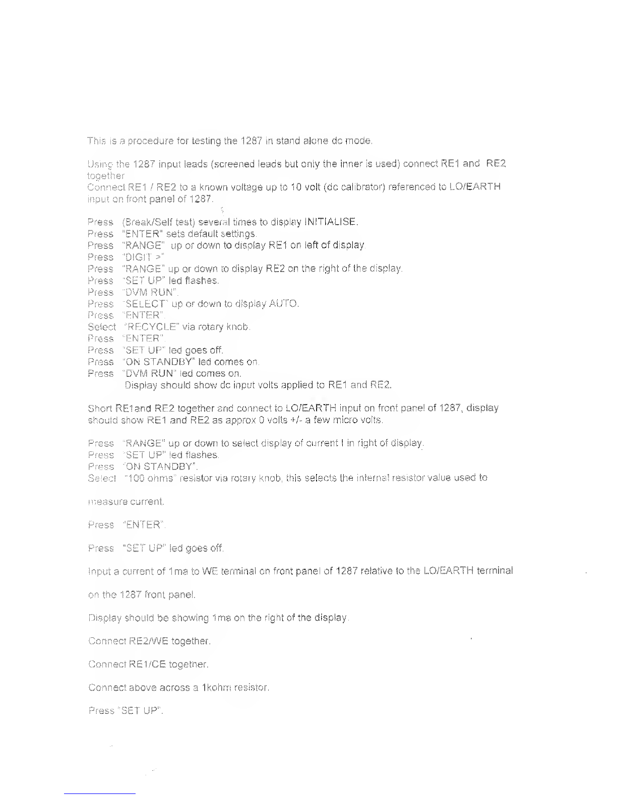
!his is aprocedure for testing the 1287 iri stand alone dc mode.
Using the 1287 input leads (screened leads but only the inner is used) connect RE1 and RE2
together
Connect RE1 /RE2 to aknown voltage up to 10 volt (dc calibrator) referenced to LO/EARTH
input on front panel of 1287.
(Break/Self test) several times to display INITIALISE.
"ENTER” sets default settings.
"RANGE” up c-r down to display RE1 on left of display
"DIGIT >“
"RANGE” up o.r down to display RE2 on the right of the display.
SET UP” led flashes.
DVM RUN”.
SELECT” up or down to display AUTO.
ENTER”.
"RECYCLE" via rotary knob.
"ENTER”.
"SET UP” led goes off.
"ON STANDBY" led comes on.
“DVM RUN” led comes on.
Display should show dc input volts applied to RE1 and RE2.
Short REIand RE2 together and connect to LO/EARTH input on front pane! of 1287,. display
should show RE1 and RE2 as approx 0volts +/- afew micro volts.
Press
Press
Select
"RANGE” up or down to select. <
SET UP” led flashes.
"ON STANDBY”.
"IOC ohms” resistor via rotary k
display of current 1in right of display.
mob, this selects the interns! resistor value used to
measut ecurrent.
Press "ENTER”
Press “SET UP" led goes off.
Input acurrent of Ima to WE terminal on front panel of 12.87 relative to the LO/EARTH terminal
on the 1287 front panel.
Display should be showing Ima on the right of the display.
Press
Press
Press
Press
Press
Press
Press
Press
Press
Press
Press
Connect RE2/WE together.
Connect RE1/CE together.
Connect above across aIkohrrt resistor
Press "SET UP”.

olartron
Solartron Analytical
Unit B1 Armstrong Mall,
Farnborough, Hampshire
England GU14 0NR
DECLARATION OF CONFORMITY cc
The directives covered by this declaration ^|
73/23/EEC Low voltage Equipment Directive, amended by 93/68/EEC
89/336/EEC Electromagnetic Compatibility Directive, amended by 92/31/EEC &93/68/EEC
Product(s)
1287A Electrochemical Interface
Basis on which conformity is being declared
The product(s) identified above comply with the requirements of the EU directives by meeting
the following standards:
EN50081 -1 :1992 Electromagnetic Compatibility -Generic Emission Standard
Part ^Residential, commercial and light industry.
EN50082-1 :1 992 Electromagnetic Compatibility -Generic Immunity Standard
Part 1:Residential, commercial and light industry.
EN61 01 0-1 :1 993 Safety requirements for electrical equipment for measurement,
control and laboratory use.
Accordingly the CE mark has been applied to this product.
Signed
EN50082-1 :1992
EN61 010-1 :1993
4aS,
For and on behalf of Solartron Analytical, adivision of Solartron Group Limited
Authority: Engineering Manager
Date: October 1996
REGISTERED IN ENGLAND No.2852989. REGISTERED OFFICE: BYRON HOUSE, CAMBRIDGE BUSINESS PARK, CAMBRIDGE, CB4 4WZ
Approved to BS EN ISO 9001 :1 994 and BS EN 123000
ARoxboro Group company


GENERAL SAFETY PRECAUTIONS
The equipment described in this manual has been designed in accordance with
IEC publication 1010 Safety Requirements for Electronic Measuring Apparatus,
and has been supplied in asafe condition. To avoid injury to an operator or
service technician the safety precautions given below, and throughout the manual,
must be strictly adhered to, whenever the equipment is operated, serviced or
repaired. For specific safety details, please refer to the relevant sections within
the manual.
The equipment is designed solely for electronic measurement and should be used
for no other purpose. Solartron accept no responsibility for accidents or damage
resulting from any failure to comply with these precautions.
GROUNDING
To minimize the hazard of electrical shock it is essential that the equipment is
connected to aprotective ground whenever the power supply, measurement or
control circuits are connected, even if the equipment is switched off.
PROTECTIVE GROUND is connected via the ac supply cord. The cord must be
plugged into an ac line outlet with aprotective ground contact. When an extension
lead is used, this must also contain aground conductor. Always connect the ac
supply cord to the supply outlet before connecting the control and signal cables;
and, conversely, always disconnect control and signal cables before disconnecting
the ac supply cord. The ac ground connection must have acontinuous current
rating of 25A.
AC SUPPLY VOLTAGE
Never operate the equipment from aline voltage or frequency in excess of that
specified. Otherwise, the insulation of internal components may break down and
cause excessive leakage currents.
FUSES
Before switching on the equipment check that the fuses accessible from the
exterior of the equipment are of the correct rating. The rating of the ac line fuse
must be in accordance with the voltage of the ac supply.
Should any fuse continually blow, do not insert afuse of ahigher rating. Switch
the equipment off, clearly label it "unserviceable" and inform aservice technician.
EXPLOSIVE ATMOSPHERES
NEVER OPERATE the equipment, or any sensors connected to the equipment, in
a potentially explosive atmosphere. It is NOT intrinsically safe and could possibly
cause an explosion.
NOTES, CAUTIONS AND WARNINGS
For the guidance and protection of the user, Notes, Cautions and Warnings appear
throughout the manual. The significance of these is as follows:
NOTES highlight important information for the reader’s special attention.
CAUTIONS guide the reader in avoiding damage to the equipment.
WARNINGS guide the reader in avoiding ahazard that could cause injury or
death.
Continued overleaf.

SAFETY PRECAUTIONS (continued from previous page)
SAFETY SYMBOLS
For the guidance and protection of the user, the following safety symbols appear
on the equipment:
SYMBOL MEANING
Refer to operating manual for detailed instructions of use.
Hazardous voltages.
Protective conductor terminal. This must be connected to
ground before operating the equipment.
AVOID UNSAFE EQUIPMENT
The equipment may be unsafe if any of the following statements apply:
•Equipment shows visible damage.
•Equipment has failed to perform an intended operation.
•Equipment has been subjected to prolonged storage under unfavorable
conditions.
•Equipment has been subjected to severe physical stress.
If in any doubt as to the serviceability of the equipment, don’t use it. Get it
properly checked out by aqualified service technician.
LIVE CONDUCTORS
When the equipment is connected to its measurement inputs or supply, the
opening of covers or removal of parts could expose live conductors. The
equipment must be disconnected from all power and signal sources before it is
opened for any adjustment, replacement, maintenance or repair. Adjustments,
maintenance or repair, must be done only by qualified personnel, who should
refer to the Servicing Manual.
EQUIPMENT MODIFICATION
To avoid introducing safety hazards, never install non-standard parts in the
equipment, or make any unauthorized modification. To maintain safety, always
return the equipment to Solartron for service and repair.
1IVI I IU
S1 1287 Electrochemical Interface
Contents
CHAPTER
1Introduction
Introduces the facilities of the SI1287 Electrochemical Interface, gives a
comparison to the 1286, and summarizes the content ofthe manual.
2Using the SI1287
Guides you through some simple uses of the SI1287 and signposts the way
to more advanced uses.
3SI 1287 Parameters and Commands
Provides alogical breakdown of the facilities and the commands that are
used to drive them.
4Remote Control
Describes the RS232 and GPIBfacilities of the SI1287.
5Using the SII 287 with an FRA
Guides you through connection and setup of the SI1287 when used with an
FRA
.
APPENDIX
AInstallation Procedure
BError Codes
CSI1 287 Specification
INDEX
CSB/SI1287 User Guide/Issue AA 0.1

UUI ILCI no
,(|
I
! f
0.2 CSB/SI1287 User Guide/Issue AA
Chapter 1
Introduction
Section Page
1Electrochemistry and SI1287 1.3
2Features of the SI1287 1.3
3The Structure of the SI1287 1.3
4SI1287 Improvements over 1286 1.6
5Application Software 1.7
6Further Reading 1.7
7Using the S11287 User Guide 1.8
Figure
1.1 SU287 Block Schematic 1.4
CSB/SI1287 User Guide/issue AA 1.1
'-'I 'U^lVl I
1.2 CSB/SI1287 User Guide/Issue AA
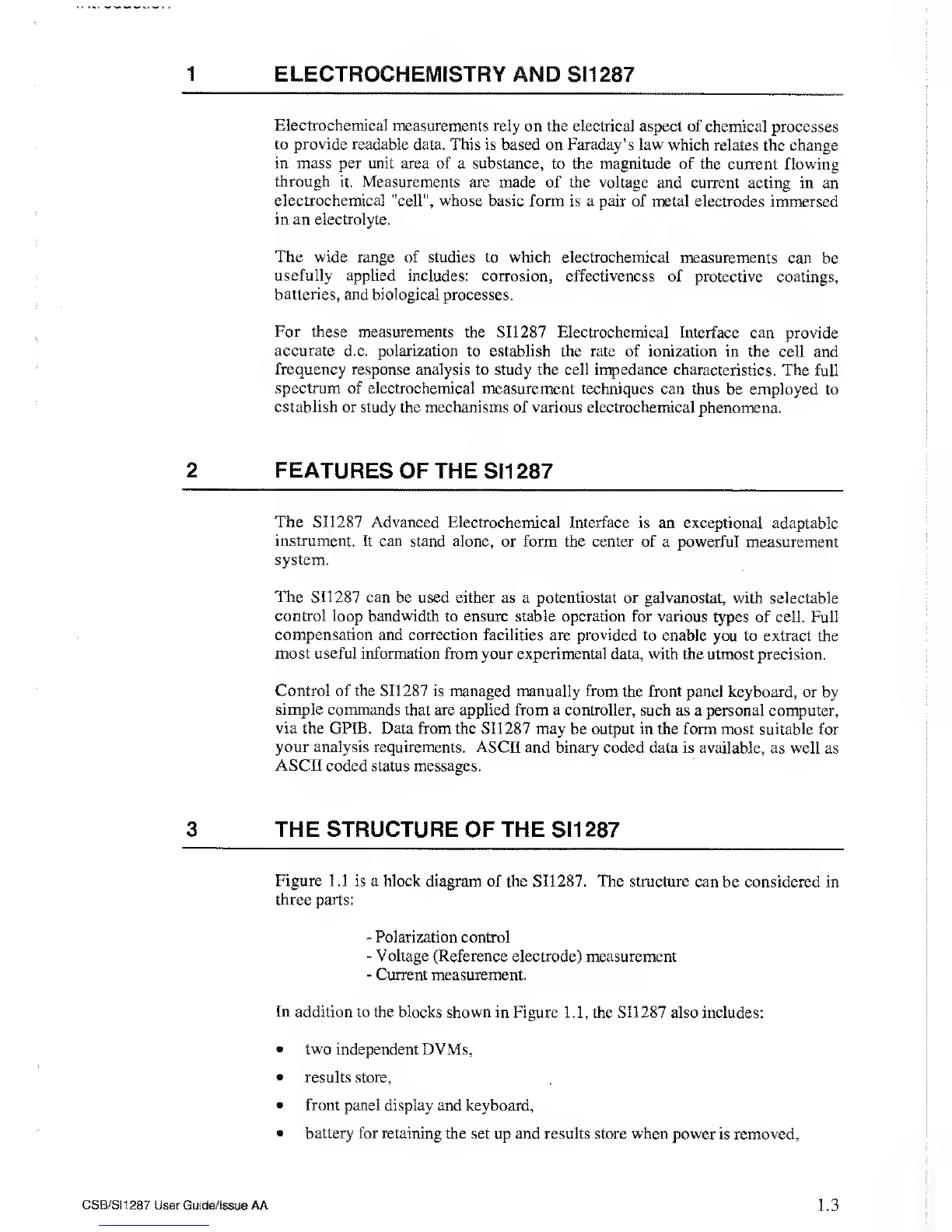
1ELECTROCHEMISTRY AND SI1287
Electrochemical measurements rely on the electrical aspect of chemical processes
to provide readable data. This is based on Faraday’s law which relates the change
in mass per unit area of asubstance, to the magnitude of the current flowing
through it. Measurements are made of the voltage and current acting in an
electrochemical "cell", whose basic form is apair of metal electrodes immersed
in an electrolyte.
The wide range of studies to which electrochemical measurements can be
usefully applied includes: corrosion, effectiveness of protective coatings,
batteries, and biological processes.
For these measurements the SI1287 Electrochemical Interface can provide
accurate d.c. polarization to establish the rate of ionization in the cell and
frequency response analysis to study the cell impedance characteristics. The full
spectrum of electrochemical measurement techniques can thus be employed to
establish or study the mechanisms of various electrochemical phenomena.
2FEATURES OF THE SI1 287
The SI1287 Advanced Electrochemical Interface is an exceptional adaptable
instrument. It can stand alone, or form the center of apowerful measurement
system.
The SI1287 can be used either as apotentiostat or galvanostat, with selectable
control loop bandwidth to ensure stable operation for various types of cell. Full
compensation and correction facilities are provided to enable you to extract the
most useful information from your experimental data, with the utmost precision.
Control of the SI1287 is managed manually from the front panel keyboard, or by
simple commands that are applied from acontroller, such as apersonal computer,
via the GPIB. Data from the SI1287 may be output in the form most suitable for
your analysis requirements. ASCII and binary coded data is available, as well as
ASCII coded status messages.
3THE STRUCTURE OF THE SI1 287
Figure 1.1 is ablock diagram of the SI1287. The structure can be considered in
three parts:
-Polarization control
-Voltage (Reference electrode) measurement
-Current measurement.
In addition to the blocks shown in Figure 1.1, the SI1287 also includes:
•two independent DVMs,
•results store,
•front panel display and keyboard,
•battery for retaining the set up and results store when power is removed.
CSB/SI1287 User Guide/Issue AA 1.3

Chapter
1
Fig
1
.1
S1
1287
Block
Schematic
•GPIB and Serial mput/output ports
®control circuitry to integrate all these facilities.
Although FRA connections are shown in the diagram for completeness, the
SI1287 does not need one to make dc measurements.
DVM
SI1287 has two independent DVMs which have a’5 x9s’ output. The DVMs
can be switched to measure avariety of different parameters independently, and
these are indicated in Figure 1.1, thus: (are-bi ^
POLARIZATION CONTROL
Polarization of the cell is acombination of dc, swept dc and an external voltage,
which normally comes from aFrequency Response Analyzer (FRA). Internal
generators within the SI1287 generate an accurate and stable dc voltage (POL)
which is added to the external (ac) signal from the FRA, to give IPOL. This
signal is used to control the current through the cell, or the voltage across the
reference electrodes, depending on whether the ECI is in galvanostat (i.e., current
controlled) or potentiostat (voltage controlled) mode.
Feedback from the relevant cell parameter is used to control the polarization. In
addition, the bandwidth of the feedback mechanism can be selected by the user to
prevent unwanted oscillations from occurring. The polarization signal is also
modified when IR compensation is used, either by adding acompensation
voltage, or by interrupting the polarization to the cell.
VOLTAGE MEASUREMENT
The voltage across the reference electrodes (ARE) is measured by adifferential
amplifier, and this voltage is used to control the polarization when the SI12S7 is
in potentiostat mode.
In order to reject any unwanted steady dc level on the cell, astable programmable
voltage, generated within SI1287, can be subtracted from the measured voltage.
If sampled IR compensation is being used, the resultant voltage is passed through
asample-and-hold circuit. The signal (ARE-Bi) is then buffered, optionally
filtered, and output to one channel of the FRA.
CURRENTMEASUREMENT
The current from the working electrode is measured by passing it through a
user-selectable resistor; this generates avoltage proportional to the current which
is then measured by a differential amplifier. This allows the working electrode to
be floating, and not connected to the instrument ground. If sampled IR
compensation is invoked, the output of the differential amplifier is passed through
asample-and-hold circuit, to yield I. Aprogrammable rejection voltage,
representing asteady current through the cell which is to be offset, can be
subtracted from the measured voltage to give (I-Bi) before it is buffered,
optionally filtered and output as avoltage (proportional to the current in the cell)
to the FRA.
RESULTS STORE
The History file is capable of storing up to 450 results, depending on the number
of instrument set-ups stored in memory (each stored set-up reduces this number
by 16).
CSB/SI1287 User Guide/issue AA 1.5

Wiiupiu
4S1 1287 IMPROVEMENTS OVER 1286
The SI1 286A ECI has been established for a number of years as one of the most
advanced instruments of its type, and has an impressive specification. The
SI1287A has an enhanced specification that enables even more sensitive
measurements to be made, and opens up new areas of application.
Asummary of the improvements is given below:
•Extra current range, giving increased current sensitivity: IpA compared to
lOpA on 1286;
•Floating Working Electrode;
•Reduced measurement noise;
•Improved DC sweep rate: 6mV/min up to 6000V/min with aresolution of
150pV/min, compared to 1286’ s6mV/min resolution;
•Increased maximum DC polarization: ±1 4.5V, compared to ±12.8V for 1286;
•Sweep freeze capability;
•Conformance to EMC standards.
Some of the benefits of these improved specifications are listed below.
The 1287 has an additional current measurement resistor which adds a200nA
range with aresolution of IpA. Together with the lpV voltage sensitivity, and
the improved measurement noise, the 1287 can measure effects which were
previously hidden to the researcher. This improvement also adds another decade
of impedance range, allowing measurements in excess of 1G£2 to be made
accurately.
The extra current range and lower measurement noise also means that frequency
sweep measurements can be made more quickly, since the integration time on the
FRA can be reduced.
Afurther benefit of this extra sensitivity and lower noise is that Electrochemical
Noise measurements -which require the accurate simultaneous measurement of
very low voltages and currents -can now be made to yield useful results.
The ability to float the working electrode is of great benefit in many industrial
applications where the working electrode has to be grounded -for tests on oil
pipelines, for example. Even in the laboratory, equipment may need to be
grounded for safety reasons, and this can now be handled by 1287.
The increased maximum polarization voltage enables experiments to be
conducted on 12volt accumulators, which typically have arest potential of >13V.
The 1287 can be programmed to freeze the polarization after aDC sweep, rather
than return it to zero. This allows any number of sweeps to be performed in
sequence without the need to turn the polarization off, to minimize disturbances
to the cell.
1.6 CSB/SI1287 User Guide/Issue AA
5APPLICATION SOFTWARE
SI1287 works equally well as astand-alone instrument, or as part of acomputer
controlled system. The advantages of using aPC for control and data storage are:
•Complex set-ups can be stored and downloaded rapidly, avoiding the need for
time consuming (and error prone) manual set-ups
•Easy-to-use mouse-driven menu selections to set up and display data
•Wide variety of display formats available
•Results can be stored on disk for later analysis and trending
•Polarization sweeps, impedance tests, harmonic analysis and EC noise tests
can be run with ease
•Equivalent circuit simulation and curve fitting facilities give greater insight
into reactions mechanisms
Other facilities include direct readout of corrosion rate and polarization
resistance, 3-dimensional plotting routines, Tafel fitting software, and batch tests
(including automatic test sequencing and full multiplexer support).
Our application software portfolio is constantly being updated. Please contact
Solartron for more information and afree copy of the latest demonstration
software.
6FURTHER READING
Understanding Electrochemical Cells,by A.M. Kauffman. (Technical Report
01 7/85) This book gives asimple non-mathematicai treatment of what happens
in an electrochemical cell during a corrosion process. It is intended for
technicians who wish to obtain an intuitive grasp of the phenomena involved.
Identification ofElectrochemical Processes by Frequency Response Analysis, by
Claude Gabrielli. (Technical Report 004/83) This book gives abroad
introduction to the many different techniques that can be used in
electrochemistry. Although written by an electrochemist for electrochemists the
book does not aim to be adeep study, but it does contain an extensive
bibliography. You are thus directed to anumber of classical treatises and
scientific papers on many subjects of interest.
Use and Applications of Electrochemical Impedance Techniques, by Claude
Gabrielli. (Technical Report No. 24) This book complements the author’s other
book (above), but is more application oriented. Again, reference is made to many
scientific papers.
Use and Analysis of EIS Data for Metals and Alloys, by Florian Mansfeld.
(Technical Report No. 26) This is acollection of reports, previously published by
Schlumberger Technologies, which describes in some detail the different
analytical processes required for data acquired by electrochemical impedance
spectroscopy. The models proposed for the simulation and fitting of EIS data are
discussed and each is illustrated by the interpretation of actual experimental data.
CSB/S1 1287 User Guide/Issue AA 1.7

Ul lopici
7USING THE SI1287 USER GUIDE
The aim of the SI1287 User Guide is to provide useful information on how best to
employ your Advanced Electrochemical Interface. To guide you in reading the
manual asynopsis of Chapters 2through 6is given below:
App’dix
c
Index
Using the SI1287
Guides you through some simple uses of the SI1287 and
signposts the way to more advanced uses.
SI1287 Parameters and Commands
Provides alogical breakdown of the SI1287 facilities and lists
the commands that are used to drive them.
Remote Control
Describes the RS423 and GPIB facilities of the SI1287 and
gives details of the remote commands available.
Using the SI1287 with an FRA
Guides you through the connection and setup of the
instrument when used with an FRA.
Installation
Gives full detail's of how to install the SI 1287.
Error Codes
Lists the error codes and explains the meaning of each one.
SI 1287 Specification
Contains the full specification of the SI1287.
Index
Cross references major topics within the manual.
1.8 CS8/SI1287 User Guide/Issue AA
Chapter 2
Using the S1 1287
Section Page
1Introduction 2.3
2Front Panel Key Operation 2.3
2.1Key Operation 2.3
2.2 Modes of Operation 2.4
2.3 Power Up 2.4
3Connecting to the SI1287 2.5
3.1 Measurement of Grounded Electrodes 2.5
4Setting Parameters for aPotentiodynamic
Polarization Curve 2.7
4.1 External Connections 2.7
4.2 Initializing SI1 287 2.8
4.3Setting up Parameters 2.8
5Using the Display 2. 14
Figure
2.1 S11.287 Front Panel :Keys and display section 2.3
2.2 Cell Connections 2.4
2.3 12861 Test Module Circuit 2.7
2.4 Plot ofthe Sweep 2.13
2.5 Plot ofthe Potentiodynamic Polarisation Cur\>e 2.13
CSB/SI1287 User Guide/Issue AF 2.1

Ul ICiptOI c~
2.2 CSB/SI1287 User Guide/issue AF
Table of contents


