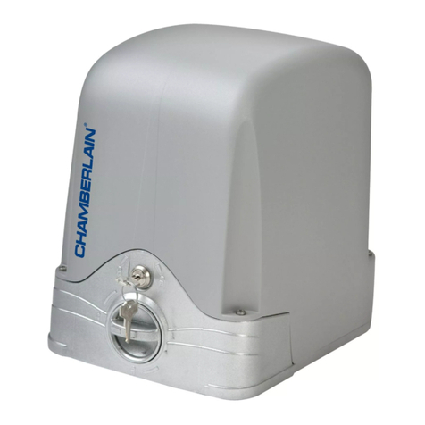
Solavis DKC400Y User manual

DKC400Y AC Sliding Gate Installation Manual www.solavis.com.au
Copyright © 2008 SOLAVIS™Doc: DKC400Y Installation Manual v1.1 page 1 of 22
Sliding Gate Opener
Model: DKC400Y
Installation Manual
WARNING
Read and thoroughly understand all instructions before installing or
operating this automatic gate opener. Failure to do so may cause serious
injury or death. This gate opener produces a high level of force. Stand
clear of the gate opener during operation and always be aware of the
hazards associated with it.

DKC400Y AC Sliding Gate Installation Manual www.solavis.com.au
Copyright © 2008 SOLAVIS™Doc: DKC400Y Installation Manual v1.1 page 2 of 22
Table of Contents
IMPORTANT—READ THIS FIRST.......................................................................................................................... 3
SAFETY ............................................................................................................................................................. 3
PRELIMINARY CHECKS ..................................................................................................................................... 3
2. Main features .............................................................................................................................................. 4
3. Main technical parameters.......................................................................................................................... 5
4. Working principle and main structure......................................................................................................... 5
Installation........................................................................................................................................................... 6
Gate preparation ............................................................................................................................................. 6
Conduit Pipes................................................................................................................................................... 6
Concrete pad ................................................................................................................................................... 7
Anchors................................................................................................................................................................ 7
Operator .......................................................................................................................................................... 7
Installation of tracks (see Fig.3)....................................................................................................................... 8
Magnets for limit switch.................................................................................................................................. 8
6. Connecting................................................................................................................................................... 9
Wiring notes for control board...................................................................................................................... 11
Control............................................................................................................................................................... 13
Adding extra remote controls (Learn):.......................................................................................................... 14
Erase remote controls: .................................................................................................................................. 14
Verify open direction..................................................................................................................................... 15
Set auto-close function.................................................................................................................................. 15
Cancel auto-close function:........................................................................................................................... 16
Pedestrian mode: .......................................................................................................................................... 16
Set width of pedestrian mode:.................................................................................................................. 16
Set auto-close function of pedestrian mode:............................................................................................ 17
Cancel both the width and the auto-close function of pedestrian mode:................................................ 17
Cancel the width of pedestrian mode, but keep the auto-close function of pedestrian mode: .............. 18
Keep the width of pedestrian mode but cancel the auto-close function of pedestrian mode:................ 18
Adjustment of the auto-reverse function: .................................................................................................... 19
Check ................................................................................................................................................................. 19
Maintenance...................................................................................................................................................... 20
Troubleshooting guide ...................................................................................................................................... 21

DKC400Y AC Sliding Gate Installation Manual www.solavis.com.au
Copyright © 2008 SOLAVIS™Doc: DKC400Y Installation Manual v1.1 page 3 of 22
IMPORTANT—READ THIS FIRST WARNING
This gate is dangerous if installed or used improperly. STAY AWAY FROM THE GATE
WHILE IT IS OPERATING. The gate can crush hands, fingers or toes, knock over persons
in the vicinity, and cause death if used improperly. KEEP CHILDREN AND ADULTS WITH
MENTAL IMPAIRMENTS AWAY FROM THE GATE. Children and adults with mental
impairments, who may not recognize the obvious dangers, are at particular risk and must
be kept away from moving parts of this gate. Damage to the gate or improper installation or
maintenance could cause additional hazards.
NEVER USE THE GATE IF IT IS DAMAGED.
SAFETY
This booklet will offer you information you may need to install your gear motor and to
safeguard your safety. However, caution is unquestionably indispensable and nothing is
better than preventing accidents.
WARNING: any repair or adjustment of working machinery is strictly prohibited unless all
the necessary precautions (electrical supply disconnected and motor off) have been taken
in order to avoid possible accidents.
WARNING: any repair must be carried out by qualified people.
WARNING: All moving mechanisms must be provided with suitable protections.
WARNING: Keep the automatic controls out of the reach of children.
WARNING: Command pulses must be given from positions where the gate is visible.
WARNING: Use transmitters only if you can see the gate.
Read carefully the instructions enclosed in this manual.
Keep this booklet in a suitable place well known to all interested people.
PRELIMINARY CHECKS
The following gate characteristics should exist for the opener installation to be successful:
The gate must be balanced
You must be able to carry out manual closing and opening of the gate without
any effort.
Make sure that the gate has a solid structure and that there is no friction points in
its movement.
The weight of the gate should not exceed 600kg.
Turn off all power to the gate opener until installation is completed.

DKC400Y AC Sliding Gate Installation Manual www.solavis.com.au
Copyright © 2008 SOLAVIS™Doc: DKC400Y Installation Manual v1.1 page 4 of 22
2. Main features
The device is used to drive a sliding gate.
Stop and reverse function if the gate is obstructed during operation.
Supports up to 100 remote controls.
User programmable and user erasable remote codes.
Infrared terminal (N.C) is supplied to use.
Auto-close function
Pedestrian mode.
Manual key release design for emergency purposes.
Integrated control board for easier installation
The gate opener can be integrated with an alarm lamp, photocell and other security
devices.
Soft start and soft stop functions to minimise wear and tear on your gate and gate
hardware and ensure quiet and safe operation.

DKC400Y AC Sliding Gate Installation Manual www.solavis.com.au
Copyright © 2008 SOLAVIS™Doc: DKC400Y Installation Manual v1.1 page 5 of 22
3. Main technical parameters
Model Name
DKC400Y
Power supply:
220V ~240V
Motor speed:
1400r/min
Gate moving speed (output gear 24 teeth)
14m/min
Gate moving speed (output gear 19 teeth)
11m/min
Output torque
14N.m
Max. gate weight
600kg
Remote control range
30m
Remote control frequency
433.92mHz
Working temperature
-10°C ~ +55°C
Limit switch
Magnetic or Spring limit switch
Remote Control
Single Button Mode
Auto Close Time
0~45 sec
Noise
less than 62dB
Working Time
90 sec
4. Working principle and main structure
The device is composed of a single-phase motor, worm and worm gear. The main shaft of
the motor rotates the worm with the clutch engaged; the worm rotates the worm gear and
output gear, which pushes the rack attached to the sliding gate, thus moving the gate.
The device is equipped with a thermal protector; the thermal protector will switch off the
motor automatically when the temperature exceeds 120°C and will switch on the motor
when the temperature drops to around 85°C.

DKC400Y AC Sliding Gate Installation Manual www.solavis.com.au
Copyright © 2008 SOLAVIS™Doc: DKC400Y Installation Manual v1.1 page 6 of 22
Installation
This gate opener is a rack driven operator which works by forcing a rack past the driving
gear. An illustration is shown in Figure 1 below. The gate operator should be installed on
the inside of the gate.
Gate preparation
Be sure the gate is properly installed and slides smoothly before installing the gate
operator. The gate must be plumb, level, and move freely. Manually open and close the
gate, checking for any friction points.
Fig.1
Conduit Pipes
PVC conduit pipes should be used to protect electrical cabling. Ideally, the conduit pipes
should be set into the concrete when it is poured. Ensure that all cables are protected from
sharp or rough objects to avoid any damage.

DKC400Y AC Sliding Gate Installation Manual www.solavis.com.au
Copyright © 2008 SOLAVIS™Doc: DKC400Y Installation Manual v1.1 page 7 of 22
Concrete pad
The base of the unit should be installed on a concrete slab/pad to ensure proper stability.
The concrete pad should be approximately 300mm x 200mm x 200mm deep to ensure
proper operation.
Anchors
You can use the anchors, bolts, washers and nuts that are provided with the operator.
These anchors must be set into the concrete when it is poured. You can also use other
ground anchors such as Dynabolts ™to install in existing concrete.
Operator
In locations where frost occurs, mount the gate operator on an installation pad as shown in
Fig.2. Check the operator and make sure it is lined up with the gate.
Nut
Bolt
Anchor
Nut
Spring washer
Plain washer
Gear
Gate operator
Installation pad
Conduit
Wires
Fig.2

DKC400Y AC Sliding Gate Installation Manual www.solavis.com.au
Copyright © 2008 SOLAVIS™Doc: DKC400Y Installation Manual v1.1 page 8 of 22
Installation of tracks (see Fig.3)
Fix the three nuts (included with the metal tracks) on the rack element.
Lay the first piece of track on the gear and weld the first nut on the gate.
Move the gate manually, checking making sure the track isn’t resisting movement at the
gear, and weld the second and third nut.
Place the second metal track near the first one. Move the gate manually and weld the
three nuts as per the first track. Repeat until the gate is fully covered.
When the rack has been installed, ensure that it rolls smoothly on the driving gear.
The space between rack and gear should be about 1mm.
Fig.3
Magnets for limit switch
For added safety, it is recommended that limit devices such as a ground stop be placed at
both ends of the gate to prevent the gate from sliding out of its rails. This is only a
precaution; the gate operator actually uses a magnetic limit switch to control the open and
closed positions of the gate.
Install the magnet as shown in Fig.4 and Fig.5.
Release the gear clutch and push the sliding gate manually to pre-determine the
positions of the limit switch magnets.
Fix the magnet brackets to the rack and tighten the gear clutch. The lower bracket is
used as the opening limit switch and should be installed on the rack for the open
position. Similarly, the higher magnet is for the closed position. Adjust the position of
gate operator, the magnet should be 10~15mm away from the magnetic limit switch
to work correctly.
Now open and close the gates via the operator. Make final adjustments to the
position of the magnets to ensure that your open and closed gate positions are
correct.

DKC400Y AC Sliding Gate Installation Manual www.solavis.com.au
Copyright © 2008 SOLAVIS™Doc: DKC400Y Installation Manual v1.1 page 9 of 22
10-15mm
Magnet
Gate
Nut
Rack
Gear
Guide rail
122mm
Magnetic limit
switch inside
Fig.4
Fig.5
6. Connecting
Make sure that the power is OFF before making any electrical connections.
Perform the wiring (See Fig.6 and wiring notes for control board).

DKC400Y AC Sliding Gate Installation Manual www.solavis.com.au
Copyright © 2008 SOLAVIS™Doc: DKC400Y Installation Manual v1.1 page 10 of 22
Fig.6 Control board scheme

DKC400Y AC Sliding Gate Installation Manual www.solavis.com.au
Copyright © 2008 SOLAVIS™Doc: DKC400Y Installation Manual v1.1 page 11 of 22
Wiring notes for control board
1. Power switch: ON/OFF
2. Fuse: DKC400Y: 5A, Ø5x20 /DKC400UY: 10A, Ø5x20
3. Antenna: ANT
4. Beeper: DC12V
5. Dip-switch
6. Memory Card: 93C66
7. MCU: PIC 16C57C
8. Three button switch / single-button switch (keypad):
Three-button switch (normally open, three-button mode): T (Stop), G (Close), K
(Open), COM (Common)
Button switch Control board
terminal X10
T
G
K
COM
COMMON
STOP
CLOSE
OPEN
T
G
K
COM
N.O.
Schematic diagram Wiring diagram
Single-button switch / Keypad (normally open, single-button mode): T (Not used), G
(Open priority), K (Open/stop/close), COM (Common)
To install the keypad attach one lead of your keypad to ‘K’ of terminal X10 and the other
to the ‘COM’. The keypad will function in single channel mode.
Control board
terminal X10
Button switch
keypad
Not used
G
T
COM
K
Com
Signal
NO
com
K
Open
G
com
NO
Schematic diagram Wiring diagram

DKC400Y AC Sliding Gate Installation Manual www.solavis.com.au
Copyright © 2008 SOLAVIS™Doc: DKC400Y Installation Manual v1.1 page 12 of 22
9. Limit switch: CL (Close limit), CO (Com), OP (Open limit),DC12V (Output power
supply)
CL
COM
OP
N.C. (For N.C. limit switch)
CL
COM
OP
N.O. (For N.O. limit switch)
Limit switch mode is adjustable by DIP-switch. (See table 1)
Schematic diagram
Control board
Motor wiring
terminal
E
W
VCC
U
OPCOM
CL
MOTOR
REED SWITCHES
SWITCH
WV
COM/UOPEN
COMCLOSED
RELEASE
X9
Wiring diagram
10.Output power supply: +12V (DC +12V), COM (CO),DET (Loop detector), I.R.
(Infrared N.C)
COM
GND
+12V
Out COM
I.R
COM
+12V
Terminal
X8, No.10
Terminal
X8, No.10
I.R
COM
Out
COM
AC24V AC24V Terminal
X5,No.11
Infrared Control board Infrared Control board
Infrared with DC input Infrared with AC input
Loop detector with DC input
Control board
Loop detector
Terminal
X8, No.10
+12V
COM
DET
COM
Out
+12V
GND
COM
Loop detector with AC input
Control board
Loop detector
Terminal
X5,No.11
AC24VAC24V
COM Out COM
DET
Terminal
X8, No.10
Schematic diagram

DKC400Y AC Sliding Gate Installation Manual www.solavis.com.au
Copyright © 2008 SOLAVIS™Doc: DKC400Y Installation Manual v1.1 page 13 of 22
11.Output power supply: AC24V
12.Power Indicator: LED
13.Learn button: AN
14.Force Adjustor (VR1): Clockwise +, Counterclockwise –
15.Power Transformer: DKC400Y: 220V/12Vx2 / DKC400UY: 110V/12Vx2
16.Sampling Transformer: 110V/8.8V 4W
17.Alarm Lamp: DKC400Y:AC220V / DKC400UY:AC110V
18.Motor Capacitor
19. Motor: U (com), V (Positive direction), W (Opposite direction), E (grounding),
RELEASE CLOSED COM OPEN COM/U V W
SWITCH REED SWITCHES MOTOR
CL COM OP UC C
VWE
Motor wiring
terminal
Control board
X2
Wiring diagram
20.Power Input: E (Earth), L (Live), N (Neutral) DKC400Y: AC220 / DKC400UY: AC110V
Control
The remote control works in a single channel mode. It has four buttons. See Fig.7
remote control. The function of button 1, button 2, and button 3 are the same. With
each press of the remote control button which has been programmed, the gate will
close, stop, open or stop cycle. Button 4 is available for pedestrian mode.
You can program/learn button 1, button 2 and button 3 individually. You also can
program/learn two buttons or three buttons together, but you need repeat the
program/learn process if you want to use more than one button.

DKC400Y AC Sliding Gate Installation Manual www.solavis.com.au
Copyright © 2008 SOLAVIS™Doc: DKC400Y Installation Manual v1.1 page 14 of 22
Button 2
Button 1
Button 3
Button 4
Fig.7 Remote control
Adding extra remote controls (Learn):
Press the button ‘AN’ (See Fig.6 terminal 13) on the control board, then the ‘LED2’
will flash once, the beeper will ring for about 1 second. Then press the remote
control button which you want to use, the ‘LED2’ will flash on and off again and the
beeper will ring for about 2 seconds. The learning process is finished.
Up to 100 remote controls may be used.
Erase remote controls:
To erase all existing remote controls, press and hold ‘AN’ button, the beeper will ring,
release the button once the beeper stops ringing. This indicates that all the remote
controls have been erased completely.

DKC400Y AC Sliding Gate Installation Manual www.solavis.com.au
Copyright © 2008 SOLAVIS™Doc: DKC400Y Installation Manual v1.1 page 15 of 22
Verify open direction:
If the gate does not move in the desired direction, then you will need to reverse the motor
operating direction. Open the black plastic case and exchange wires ‘V’ with ‘W’, and also
exchange wires ‘OP’ with ‘CL’.
Table 1 DIP-switch
(See Fig.6 terminal 5)
Position
DIP-switch
Function
1
ON
Limit switch mode is NC.
OFF
Limit switch mode is NO.
2
ON
Auto-close function and auto-close function of pedestrian mode
are available.
OFF
Both Auto-close function and auto-close function of pedestrian
mode are shut off.
3
ON
Programming / In this position the control board is in
programming condition, DO NOT leave it in this position for
normal operation.
OFF
Normal / In this position the control board can be normally used.
Set auto-close function
This feature can be selected to make the gate stay open for some seconds before it
automatically closes. The auto-close time can be adjusted to between 0 and 44 seconds
Please turn the second and the third DIP-switch (See Fig.6 terminal 5) to the ON
position.
Press the remote control button (button 1, button 2 or button 3) that has been
programmed to open the gate (see Verify open direction section).
Stop the gate at any position by pressing the same button, pause for how long you
want your gate to stay open before automatically closing. This is called the auto-
close time. The range is between 0-44 seconds.
Close the gate by pressing the same button. Press the button again to stop the gate
or let the gate stop at its closed position automatically if the limit switch is reached.

DKC400Y AC Sliding Gate Installation Manual www.solavis.com.au
Copyright © 2008 SOLAVIS™Doc: DKC400Y Installation Manual v1.1 page 16 of 22
After this setup is complete, return DIP-switch 3 to OFF position immediately.
The auto-close function has now been set.
Cancel auto-close function:
Please turn the second and the third DIP-switch (see Fig.6 terminal 5) to the ON
position.
Press the remote control button (button 1, button 2 or button 3) that has been
programmed to open the gate (see Verify open direction section).
Stop the gate at any position by pressing the same button, wait until the gate closes
automatically (45 sec.).
Press the same button to stop the gate or let the gate stop at its closed position
automatically if the limit switch is reached.
After this setup is complete, return DIP-switch 3 to OFF position immediately. Thus
the auto-close function has been canceled.
Pedestrian mode:
Pedestrian mode can be used to open the gate partially to allow pedestrian traffic to enter.
Set width of pedestrian mode:
Please turn the second and the third DIP-switch (See Fig.6 terminal 5) to the ON
position.
Press button 4 to open the gate (see Verify open direction section), Wait until the
gate travels the distance you want to set for pedestrian mode (the range is between
0.3m-1.5m or 3-10 sec.)
Then press the same button/button 4 to stop the gate, pause for a few seconds and
close the gate by pressing the same button/button 4.
Press the same button again to stop the gate or let the gate stop at its closed
position automatically if the limit switch is reached.
After this setup is complete, return DIP-switch 3 to OFF position immediately.
The width has been set for pedestrian mode.
If you open the gate with button 4, the gate will stop at the position you have set above.

DKC400Y AC Sliding Gate Installation Manual www.solavis.com.au
Copyright © 2008 SOLAVIS™Doc: DKC400Y Installation Manual v1.1 page 17 of 22
Set auto-close function of pedestrian mode:
Please turn the second and the third DIP-switch (See Fig.6 terminal 5) to the ON
position.
Press button 4 to open the gate (see Verify open direction section), wait between
3-10 seconds, then press the same button/button 4 to stop the gate.
Now pause for however long you want your gate to stay open before automatically
closing. This is called the ‘auto-close time for pedestrian mode’. The range is
between 1-44 seconds.
Close the gate by pressing the same button/button 4.
Press the same button again to stop the gate or let the gate stop at its closed
position automatically if the limit switch is reached.
After this setup is complete, return DIP-switch 3 to OFF position immediately.
The auto-close function of pedestrian mode has been set
Note: the new width of the pedestrian mode entry has been re-programmed in the device
and replaced the original width you have set in the Set width of pedestrian mode section
earlier.
If you open the gate with button 4, the gate will stop at the position you have set, and after
pausing for the time you have set, it will close automatically.
Cancel both the width and the auto-close function of pedestrian mode:
Please turn the second and the third DIP-switch (See Fig.6 terminal 5) to the ON
position.
Press button 4 to open the gate (see Verify open direction section).
Wait for more than 15 seconds. Then press the same button/button 4 to stop the
gate.
Wait until the gate closes automatically (45 sec.).
Press the same button/button 4 to stop the gate or let the gate stop at its closed
position automatically if the limit switch is reached.
After this setup is complete, return DIP-switch 3 to OFF position immediately.

DKC400Y AC Sliding Gate Installation Manual www.solavis.com.au
Copyright © 2008 SOLAVIS™Doc: DKC400Y Installation Manual v1.1 page 18 of 22
Both the width and the auto-close function of the pedestrian mode have been
erased.
Cancel the width of pedestrian mode, but keep the auto-close function of pedestrian
mode:
Please turn the second and the third DIP-switch (See Fig.6 terminal 5) to the ON
position.
Press button 4 to open the gate (see Verify open direction section).
Wait for more than 15 sec. Then press the same button/button 4 to stop the gate.
Pause for how long you want your gate to stay open before automatically closing.
The range is between 0-44 seconds.
Then press the same button/button 4 to close the gate.
Press the same button again to stop the gate or let the gate stop at its closed
position automatically if the limit switch is reached.
After this setup is complete, return DIP-switch 3 to OFF position immediately.
Note: the new auto-close time for pedestrian mode has replaced any auto-close time for
pedestrian mode that you might have set earlier.
Keep the width of pedestrian mode but cancel the auto-close function of pedestrian
mode:
Please turn the second and the third DIP-switch (See Fig.6 terminal 5) to the ON
position.
Press button 4 to open the gate (see Verify open direction section).
Wait until the gate travels the distance you want to set for pedestrian mode (the
range is between 0.3m-1.5m or 3-10 sec.)
Press the same button/button 4 to stop the gate.
Wait until the gate closes automatically (45 sec.). Press the same button again to
stop the gate or let the gate stop at its closed position automatically if the limit switch
is reached.
After this setup is complete, return DIP-switch 3 to OFF position immediately.

DKC400Y AC Sliding Gate Installation Manual www.solavis.com.au
Copyright © 2008 SOLAVIS™Doc: DKC400Y Installation Manual v1.1 page 19 of 22
You are finished, the width for pedestrian opening has been preserved, but the auto-
close function has removed.
Note: the new width for pedestrian mode has replaced any previous pedestrian mode
opening width which you might have set.
Adjustment of the auto-reverse function:
Rotate the ‘VR1’ knob (See Fig.6 terminal 14) with a screwdriver, the resistance can
be increased (or decreased) by rotating clockwise (or counterclockwise).
If you turn the variable resistor clockwise it will increase the sensitivity. If you turn the
variable resistor counterclockwise, it will decrease the sensitivity.
If the gate fails to top in the event of an obstruction, this means that the sensitivity
has not been adjusted properly. For example if the gate fails to stop, the sensitivity
might not be high enough to recognize that there is an obstruction.
Note:
Please exchange wires ‘V’ and ‘W’ if the auto-reverse direction is wrong. Exchange wires
‘OP’ and ‘CL’ if the limit direction is wrong.
Check
Check the power supply, grounding and wiring before running the device.
Release the gear clutch with the release key to determine whether or not the gate
can be moved manually. If everything is in good working order, tighten the clutch
with the key.
Switch on the power and run the device to ensure that the gate is sliding smoothly.
Adjust the magnet position until the gate opens and closes properly at the intended
positions.
The motor is only designed to work for less than 5 minutes. If is runs continually for
an extended period of time, a thermal protector shut off power to prevent damage.

DKC400Y AC Sliding Gate Installation Manual www.solavis.com.au
Copyright © 2008 SOLAVIS™Doc: DKC400Y Installation Manual v1.1 page 20 of 22
Maintenance
Keep operator clean at all times.
Ensure the operator is well earthed, and correctly terminated.
Regularly grease the wheels and axles to ensure the gate moves smoothly.
Ensure the power is switched off before removing the cover.
…Troubleshooting guide (next page)
Table of contents
Popular Gate Opener manuals by other brands

Allstar
Allstar LEADER PLUS LPX1000 Series Installation and owner's manual

E.T. Systems
E.T. Systems Drive 500 User instructions
Ismartgate
Ismartgate Mini instructions

LOCKEY USA
LOCKEY USA TB-950 Magnum installation instructions

GATEXPERT
GATEXPERT GT1000DC user manual
Nice
Nice HYPPO HY 7005 Instructions and warnings for installation and use
DITEC
DITEC TRAFFIC C Installation manual, maintenance, use
Linear
Linear SG installation guide
Locinox
Locinox MAMMOTH-180 installation instructions
Viking Access Systems
Viking Access Systems I-770 Installation instructions and safety information

Eagle
Eagle EAGLE-OH installation manual
TOPP
TOPP DUEVILLE Instructions for installation and use
