SolaX Power T-BAT-SYS-HV-S25 User manual
www.solaxpower.com
eManual in the QR code or at
http://kb.solaxpower.com/
2022-12_Rev_00_EN
T-BAT-SYS-HV-S25
T-BAT-SYS-HV-S36
Installation Manual


1
Safety
General Notice
1. Contents may be periodically updated or revised. SolaX reserves the right to make
improvements or changes in the product(s) and the program(s) described in this manual
without the prior notice.
2. The installation and maintenance can only be performed by qualified personnel who:
• Are licensed and/or satisfy state and local jurisdiction regulations;
• Have good knowledge of this manual and other related documents.
3. Before installing the device, carefully read, fully understand and strictly follow the
detailed instruction of the user manual and other related regulations. SolaX shall not
be liable for any consequences caused by the violation of the storage, transportation,
installation, and operation regulations specified in this document and the user manual.
4. Use insulated tools when installing the device. Individual protective tools must be worn
during installation, electrical connection and maintenance.
5. Please visit the website www.solaxpower.com of SolaX for more information.
Descriptions of Labels
CE mark of conformity TUV certification
272687
CSA mark for UL1973 UKCA mark of conformity
The battery module may
explode Caution, risk of electric shock
Caution, risk of danger Safety glasses must be worn
Read the enclosed
documentations
Keep the battery system away from
children
Keep the battery system away
from open flames or ignition
systems
Do not dispose of the battery
module together with household
waste.
Do not dispose of the battery module together with household waste.
The battery system must be disposed of at a proper facility for environmentally-
safe recycling
Note: The table is only used for the description of symbols which may be used on the
battery. Please be subject to the actual symbols on the device.
ENGLISH
2
DANGER!
In the case of any of following circumstances, electric shock may occur:
• Disassemble the battery module;
• Touch the battery module with wet hands;
• Install or operate the battery module in places where there is excessive moisture or
liquids.
WARNING!
In the case of any of the following circumstances, personal injury or battery damage
may occur:
• The battery module was involved in a collision;
• Crush or puncture the battery module;
• Dispose the battery module in a fire;
• Expose the battery module to the temperature in excess of 140 ℉;
• Place the battery module near a heat source, such as a fireplace;
• Expose the battery module to direct sunlight;
• Allow the battery connectors to touch conductive objects, such as wires;
• Place the battery module in a high-voltage environment;
• Place any objects on the top of the battery module.
CAUTION!
• Keep children away from the battery module;
• Please check the battery module periodically. Personal injuries may be caused if not
handled properly.
NOTICE!
• In case the battery module leaks electrolyte or any other chemical materials, be
sure to avoid contact with the discharge at all times. In case of accidentally coming
into contact with them, always wash your hands thoroughly with soap and water
afterwards. In case of eye contact, seek medical attention immediately.
• If a fire breaks out where the battery module is installed, extinguish the fire before
the battery catches fire; in case the battery module catches fire, do not try to put out
the fire, and evacuate immediately.
• In case the battery module gets wet or is soaked in water, do not touch.
• In case the battery module is damaged, do not use it. Otherwise, it may result in both
personal injury and property damage.
ENGLISH
3
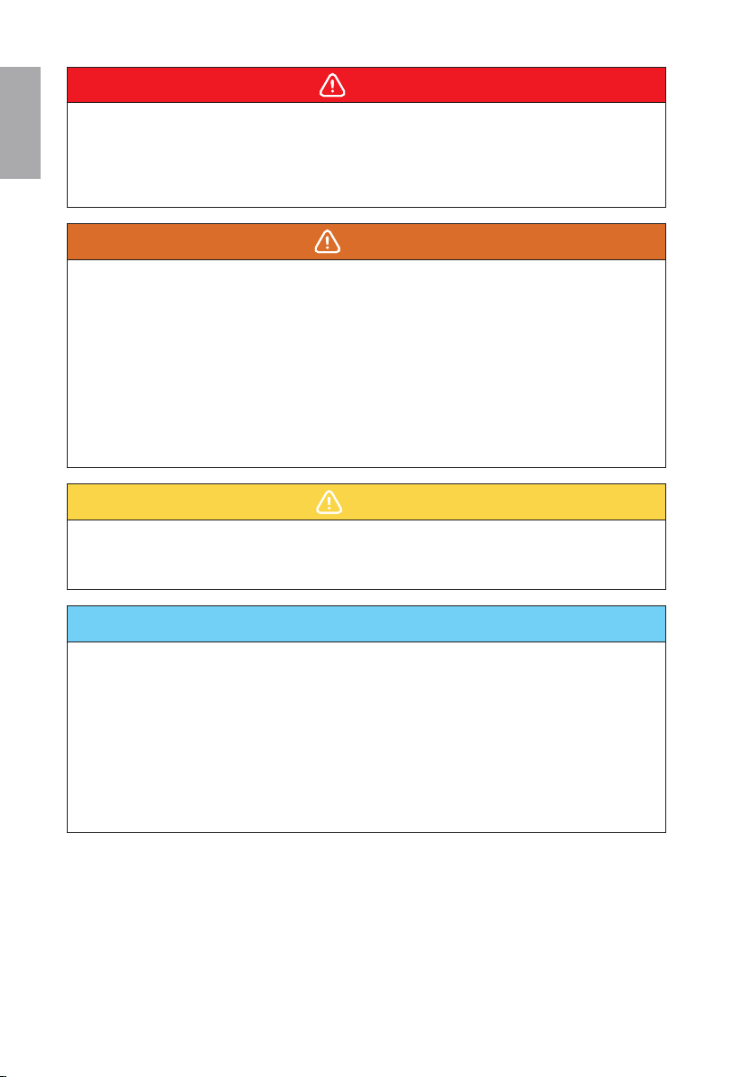
Packing List
BMS (TBMS-MCS0800)
BMS × 1 Power cable (Red) × 1*
Short power cable × 1 Adjustable bracket × 1
Adjustable L bracket × 1 Rotation wrench × 1
Expansion bolt × 2
M4 Washer
× 4
Communication cable × 1
(BMS port) Power cable (Black) × 1*
RNB5-6 Current
terminal × 2
Tapping
screw × 2 Washer × 2
Document
M4×14
Phillips-head
Screw × 4
M4×15
Phillips-head
Screw × 2
M6 Flange
nut × 2
Pedestal × 1
*Note: The mark “*“ indicates that the connector connecting inverter on the power cable,
connecting BMS and inverter, is delivered with the inverter’s accessories kit.
Battery Module (TP-HS25/ TP-HS36)
Battery module × 1
M4 Washer
× 2 Document
M4×14
Phillips-head
Screw × 2
4
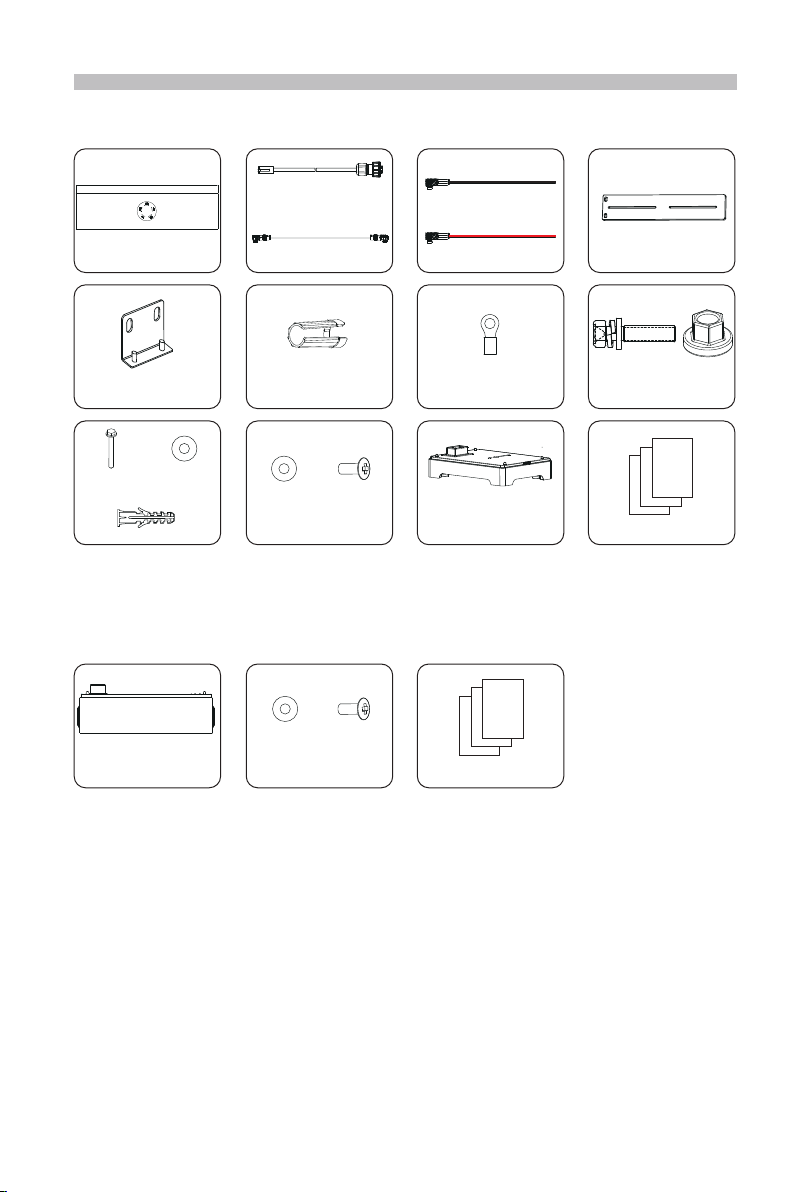
Series Box
BMS × 1 Power cable (Red) × 1
Heater cable × 1
(HEAT port) Adjustable bracket × 1
Adjustable L bracket × 3
M4 Washer
× 4
Communication cable × 1
(COM port)
Power cable (Black) × 1
Rotation wrench × 1
M4×14
Phillips Head
Screw × 4
Grounding cable × 1
M4×15
Phillips-head
Screw × 2
M6 Flange
nut × 2
Expansion bolt × 2
Tapping
screw × 2 Washer × 2
Pedestal × 1
*Note:
1. If the battery module purchased excesses 10 sets (including 10), these battery modules
should be installed in two groups, and the Series Box should be installed to connect two
groups in series.
2. If the battery module purchased is less than 9 sets (including 9), these battery
modules may be installed in one or two groups. In case of two groups, the Series Box is
recommended to install.
3. Additionally, the above accessories kit for Series Box needs to be purchased by
customers themselves.
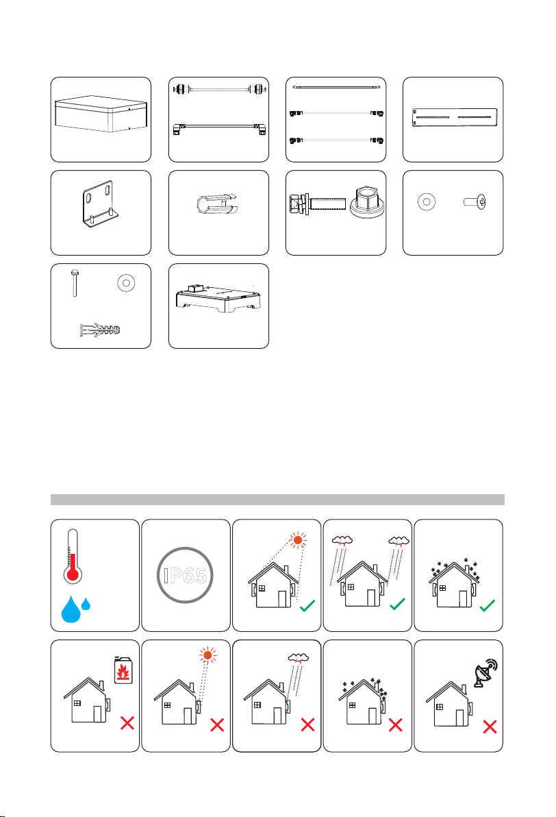
Installation Site
-30℃ -+53℃
No direct sunlight No rain exposure No snow lay up
Rain exposureNear combustibles Direct sunlight Snow lay up Near antenna
IP65
0-100%RH
5
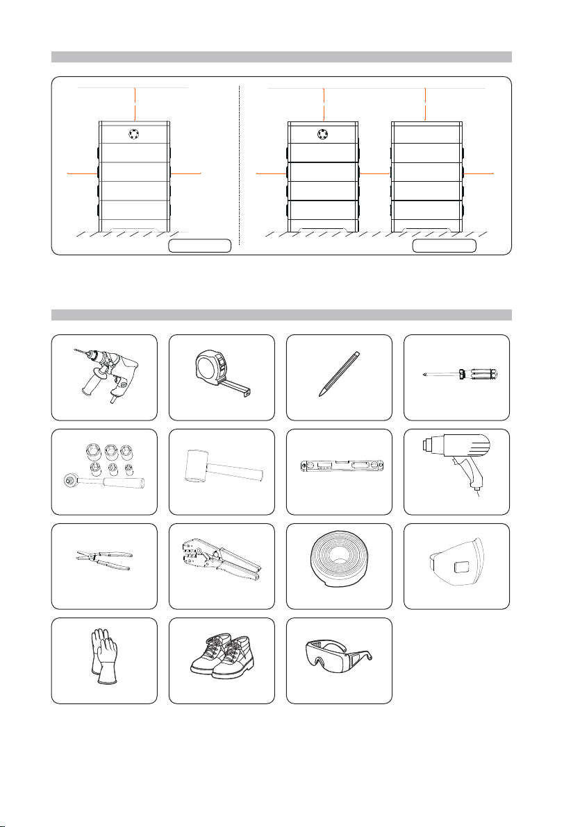
Installation Space
One group
>400 mm >400 mm
>100 mm
Two groups
>100 mm >100 mm
>400 mm
400~
800
mm
>400 mm
*Note: The above figure shows an example of installation space of "One Group" and "Two
Groups".
Installation Tools
Drill MarkerMeasuring tape Cross screwdriver
Safety gloves Safety boots Safety goggles
Anti-dust mask
MalletTorque wrench (M4) Spirit level Hot-air blower
Crimping toolWire stripper φ6 mm Hear shrink tubing

6
Mechanical Installation
*Note: Up to 9 battery modules can be installed in a group. If the battery module users
purchased excesses 10 sets (including 10), a Series Box needs to be installed to connect
two groups in series.
Installation steps without Series Box
Take the installation procedure for four battery modules as an example.
Step 1: Take out and adjust Pedestal
1 2 3
Rear
Front
The side with “R” shall be against the
wall
Turn clockwise, lower the Pedestal
Turn anticlockwise, raise the Pedestal
Step 2: Locate the Pedestal, and accurately draw the location on both sides
4
Note: The distance between the Pedestal
and the wall can be about 20~200 mm, but
the recommended distance is 60 mm.
60 mm
60 mm
Draw location
Step 3: Place the battery module
5 6
The side with “R” shall be
against the wall
Note: If the Pedestal
is shifted after placing
battery module, move
it to its original location
according to the mark
previously drawn.
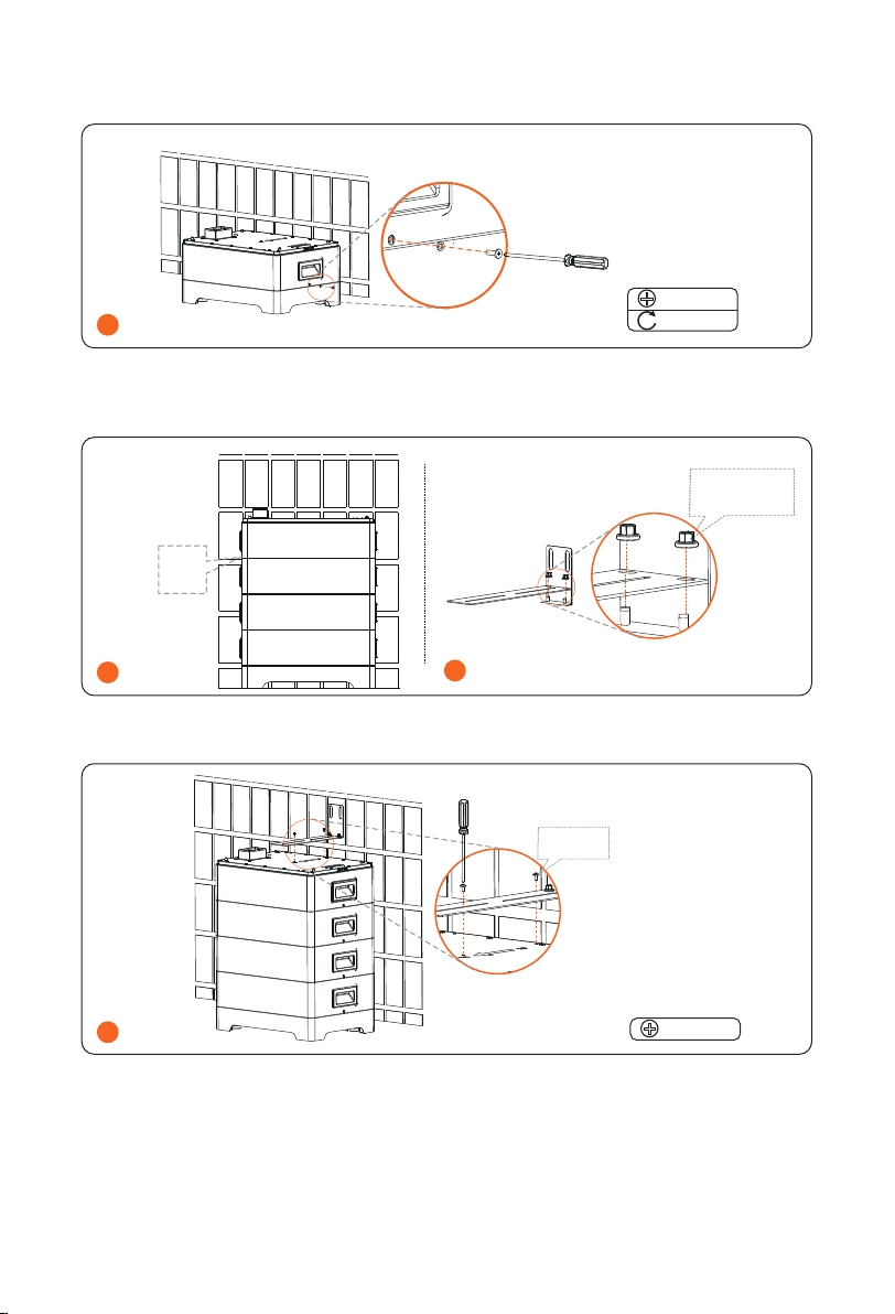
7
Step 4: Secure and tighten M4x14 Phillips-head screw on both sides
7
M4
0.9-1.1 N·m
Step 5: Repeat the Step 3 and 4 to install the rest of battery modules
Step 6: Join Adjustable Bracket and Adjustable L Bracket with M6 Flange Nut
89
Attach M6
Flange nut but
not tighten
Place battery
modules
Step 4
Step 7: Secure the assembled bracket on the battery module and wall
10
Not tighten
M4

8
11
≥ 50 mm 90°
φ10 mm
Do not remove dust cover
on the top battery
12
Remove
bracket
13
Remove
dust cover
Tighten
Tighten
Tighten
M6
5 N·m
M4
0.9-1.1 N·m
Tapping screw
4 N·m
9
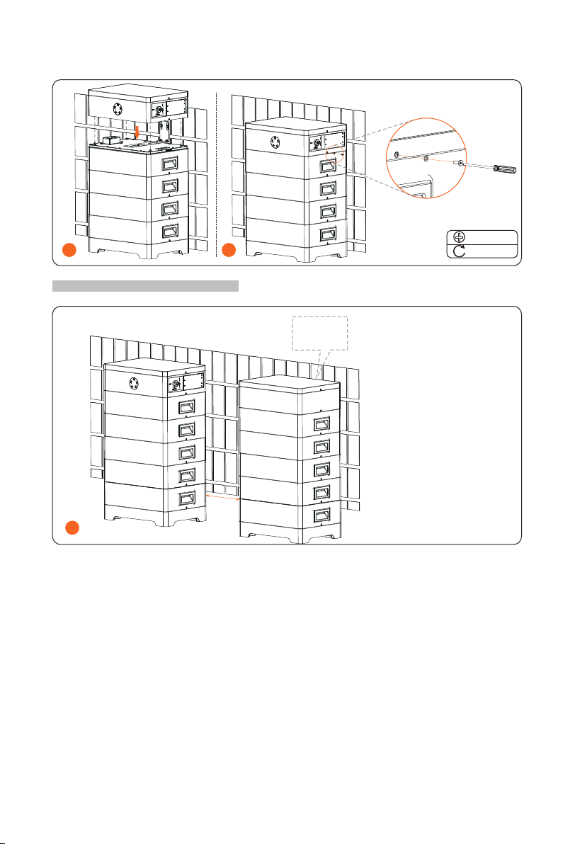
Step 8: Place BMS
14
M4
0.9-1.1 N·m
15
Both sides
Installation steps with Series Box
1
The group
also needs
bracket
BMS
Series Box
The installation procedure for
these two groups is the same as
that for one group. Please refer
to Step 1 to 8.
400 ~
800 mm

10
Current Terminal Connection
1 2
6.4 mm
Length=8-10 mm
Length=28-30 mm
Heat-shrink tubing
4-6 mm²
3 4 4.5-5 N·m
*Note: The grounding cable should be prepared by the users themselves.
Communication Connection (connecting to inverter)
1
1) White with orange stripes
2) Orange
3) White with green stripes
4) Blue
5) White with blue stripes
6) Green
7) White with brown stripes
8) Brown
15 mm
Rotate anti-clockwise
to loosen
Pin 1 2 3 4 5 6 7 8
BMS / GND / BMS_H BMS_L / A1 B1
11
Wiring
*Note: Press the door panel at both sides of BMS before wiring.
Wiring without Series Box
Left side of BMS
1
Short power cable
Lock
button
There are two terminals
at both ends.
2
Waterproof
plug
Waterproof
cap
*Note: In case of one group, a waterproof cap shall be put on the unconnected COM port,
as well as a waterproof plug on the unconnected HEAT port.
12
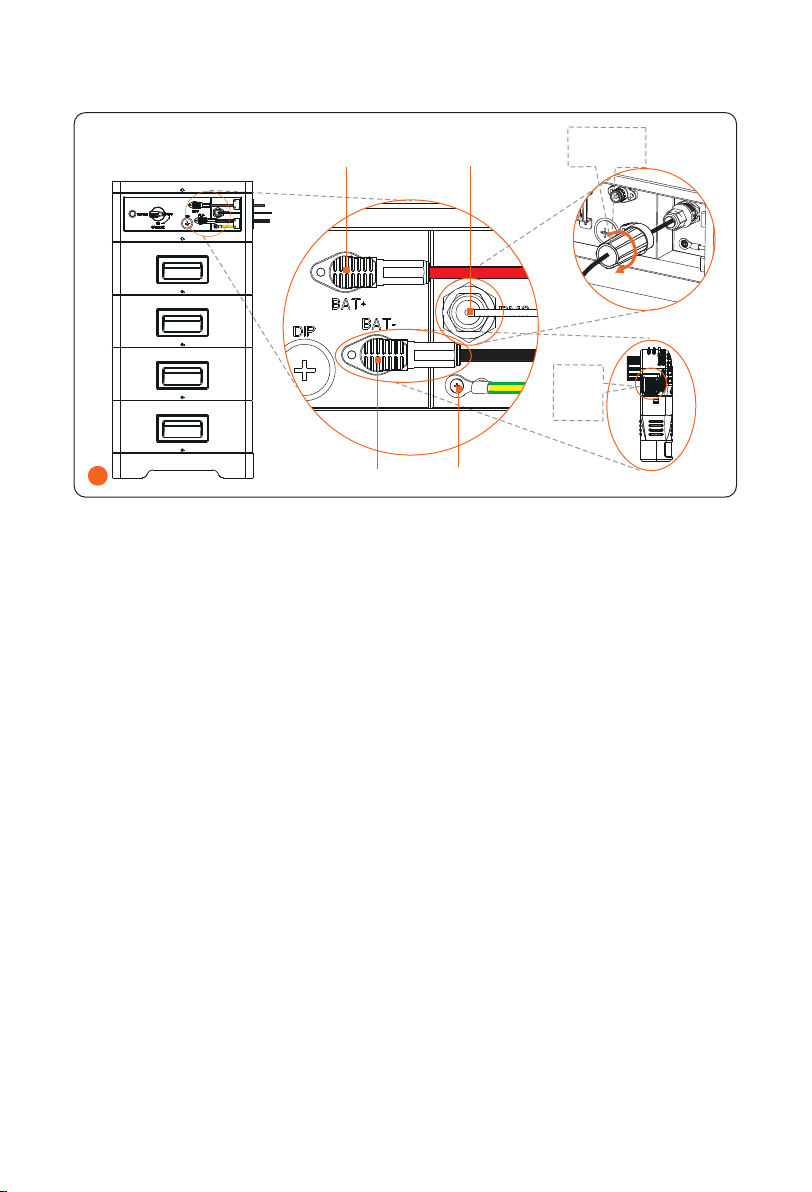
Right side of BMS
Lock
button
This type of terminal is available
on both power cables
Rotation
wrench
1
Power cable (red)
Power cable (black)
Communication cable
Grounding cable
*Note:
1. Press and hold the Lock Button while unplugging the power cable, or it cannot be pulled
out.
2. The rotation wrench is used to tighten the communication cable, and it may be removed
after tightening.
13
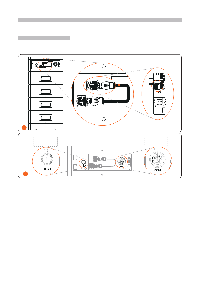
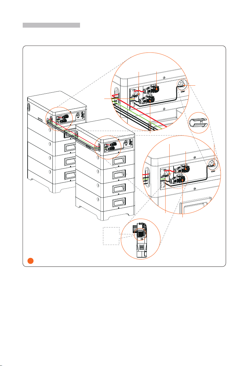
Wiring with Series Box
Wiring between BMS and Series Box
1
Power
cable (red)
Lock
button
Heater cable
(HEAT port)
Power cable (black)
Communication
cable (COM port)
Power
cable (red)
Power cable
(black)
There are two terminals at
both ends of power cable.
BMS Series Box
Grounding
cable
Grounding
cable
Rotation
wrench
Heater cable
(HEAT port)
Communication
cable (COM port)
*Note: A protective pipe is recommended to use to keep cable insulation in place and
avoid potential damages.

14
2
Rotate anti-clockwise to
remove waterproof plug
Insert heater cable into HEAT port,
and rotate clockwise to lock it
Make sure that the heater
cable is locked
Align the groove according
to the arrows

Right side of BMS
Lock
button
This type of terminal is available
on both power cables
Rotation
wrench
1
Power cable (red)
Power cable (black)
Communication cable
Grounding cable
*Note:
1. Press and hold the Lock Button while unplugging the power cable, or it cannot be pulled
out.
2. The rotation wrench is used to tighten the communication cable, and it may be removed
after tightening.
Power on the System
12
Switch on Breaker
Press Switch button
Contact Information
UNITED KINGDOM AUSTRALIA
Unit 10, Eastboro Fields, Hemdale Business
Park, Nuneaton, CV11 6GL
+44 (0) 2476 586 998
12-18 Lascelles St, Springvale VIC 3171
+61 1300 476 529
TURKEY GERMANY
Esenşehir Mah. Hale Sk. No:6/1 Ümraniye /
İSTANBUL
+90 (216) 622 58 00 (pbx)
Eisenstraße 3, 65428 Rüsselsheim am Main,
Germany
+49 (0) 6142 4091 664
USA NETHERLANDS
3780 Kilroy Airport Way, Suite 200, Long
Beach, CA, US 90806
info@solaxpower.com
Twekkeler-Es 15 7547 ST Enschede
+31 (0) 8527 37932
POLAND SPAIN
WARSAW AL. JANA P. II 27. POST
+48662430292
Thomas.[email protected]
+34683197401
ITALY BRAZIL
+393518157758
+55 (34) 9667 0319
info@solaxpower.com

Warranty
Registration
Form
For Customer (Compulsory)
Name Country
Phone Number Email
Address
State Zip Code
Product Serial Number
Date of Commissioning
Installation Company Name
Installer Name Electrician License No.
For Installer
Module ( If Any )
Module Brand
Module Size(W)
Number of String Number of Panel Per String
Battery ( If Any )
Battery Type
Brand
Number of Battery Attached
Date of Delivery Signature
Please visit our warranty website: https://www.solaxcloud.com/#/warranty or use your
mobile phone to scan the QR code to complete the online warranty registration.
For more detailed warranty terms, please visit SolaX official website: www.solaxpower.com
to check it.

320102062700Copyright © SolaX Power Technology (Zhejiang) Co., Ltd. All rights reserved.
SolaX Power Network Technology (Zhejiang) Co., Ltd.
Add.: No. 288, Shizhu Road, Tonglu Economic Development Zone,
Tonglu City, Zhejiang Province, 310000 P. R. CHINA
Tel.: +86 (0) 571 5626 0011
This manual suits for next models
1
Table of contents
Other SolaX Power Power Supply manuals


