SolaX Power T-BAT-SYS-HV User manual

320101034403
Triple Power Lithium-ion Battery
User Manual
100 Ah
SolaX Power Network Technology (Zhejiang) Co., Ltd.
Add.: No. 288, Shizhu Road, Tonglu Economic Development Zone, Tonglu City,
Zhejiang Province, 310000 P.R. CHINA
Tel.: +86 (0) 571-5626 0011
E-mail: info@solaxpower.com
Copyright © SolaX Power Technology (Zhejiang) Co., Ltd. All rights reserved.
No part of this document may be reproduced or transmitted in any form or by any means without
prior written consent of SolaX Power Technology (Zhejiang) Co., Ltd. (hereinafter referred to as
SolaX). SolaX reserves the right of final interpretation.

Contents
1 NOTE ON THIS MANUAL 1
1.1 SCOPE OF VALIDITY 1
1.2 TARGET GROUP1
1.3 SYMBOLS1
2 SAFETY2
2.1 SAFETY INSTRUCTIONS2
2.1.1 GENERAL SAFETY PRECAUTIONS2
2.1.2 EXPLANATION OF SYMBOLS3
2.2 RESPONSE TO EMERGENCY SITUATIONS4
2.2.1 LEAKING BATTERIES4
2.2.2 FIRE4
2.2.3 WET BATTERIES AND DAMAGED BATTERIES4
2.3 QUALIFIED INSTALLER5
3 PRODUCT INTRODUCTION6
3.1 PRODUCT OVERVIEW6
3.1.1 DIMENSIONS AND WEIGHT6
3.1.2 INSTALLATION SPACE7
3.1.3 APPEARANCE8
3.2 BASIC FEATURES1 0
3.2.1 FEATURES1 0
3.2.2 CERTIFICATIONS1 0
3.3 SPECIFICATIONS1 1
3.3.1 T-BAT SYS-HV CONFIGURATION LIST1 1
3.3.2 PERFORMANCE1 1
4 INSTALLATION1 2
4.1 INSTALLATION PREREQUISITES1 2
4.2 SAFETY GEAR1 2
4.3 TOOLS1 3
4.4 INSTALLATION1 3
4.4.1 CHECK FOR TRANSPORT DAMAGE1 3
4.4.2 UNPACKING1 3
4.4.3 ACCESSORIES1 4
5 EQUIPMENT INSTALLMENT1 6
5.1 INSTALLATION ENVIRONMENT REQUIREMENTS16
5.2 INSTALLATION MODE16
5.3 WALL MOUNTING16
5.3.1 OVERVIEW16
5.3.2 STEPS1 8
5.4 FLOOR MOUNTING2 5
5.4.1 OVERVIEW2 5
5.4.2 STEPS 2 6
5.5 STEPS FOR INCREASING BATTERY CAPACITY3 1
6 WIRING3 2
7 COMMISSIONING33
7.1 COMMISSIONING33
7.2 STATUS INDICATORS35
7.2.1 BMS (TBMS-MCS60060)35
7.3 SHUTTING DOWN T-BAT SYSTEM37
8 TROUBLESHOOTING3 8
8.1 TROUBLESHOOTING38
9 DECOMMISSIONING4 0
9.1 DISMANTLING THE BATTERY40
9.2 PACKING40
10 MAINTENANCE4 1
11 DISCLAIMER4 2
1 NOTE ON THIS MANUAL..................................................1
1.1 SCOPE OF VALIDITY .................................................1
1.2 TARGET GROUP .....................................................1
1.3 SYMBOLS...........................................................1
2 SAFETY ...........................................................2
2.1 SAFETY INSTRUCTIONS..............................................2
2.1.1 GENERAL SAFETY PRECAUTIONS.................................2
2.1.2 EXPLANATION OF SYMBOLS .....................................3
2.2 RESPONSE TO EMERGENCY SITUATIONS ..............................4
2.2.1 LEAKING BATTERIES.............................................4
2.2.2 FIRE .......................................................4
2.2.3 WET BATTERIES AND DAMAGED BATTERIES...................4
2.3 QUALIFIED INSTALLER ...............................................5
3 PRODUCT INFORMATION ................................................6
3.1 DIMENSIONS AND WEIGHT ..........................................6
3.2 APPEARANCE .......................................................7
3.3 BASIC FEATURES ....................................................9
3.2.1 FEATURES ......................................................9
3.2.2 CERTIFICATIONS............................................9
3.4 SPECIFICATIONS ...................................................10
3.4.1 T-BAT SYS-HV CONFIGURATION LIST ........................10
3.4.2 PERFORMANCE ...........................................10
4 PREPARATION BEFORE INSTALLATION ....................................11
4.1 PREREQUISITES ....................................................11
4.2 SAFETY GEAR......................................................12
4.3 TOOLS ..........................................................12
4.4 INSPECTION .......................................................13
4.4.1 CHECK FOR TRANSPORT DAMAGE..........................13
4.4.2 UNPACKING ...............................................13
4.4.3 ACCESSORIES.............................................14
5 INSTALLMENT ..........................................................16
5.1 INSTALLATION ENVIRONMENT REQUIREMENTS .......................16
5.2 INSTALLATION MODE ...............................................16
5.3 FLOOR MOUNTING .................................................17
5.3.1 OVERVIEW ....................................................17
5.3.2 STEP .....................................................20
5.4 WALL MOUNTING ..................................................28
5.4.1 OVERVIEW ................................................28
5.4.2 STEP......................................................31
5.5 STEPS FOR INCREASING BATTERY CAPACITY .........................40

1 Note on this Manual
1.1 Scope of Validity
This manual is an integral part of theT-BAT Series. It describes the assembly,
installation, commissioning, maintenance and failure of the product. Read it
carefully prior to operation.
T-BAT-SYS-HV-5.0 Module
T-BAT-SYS-HV-5.0 BMS
1.2 Target Group
This manual is for qualifiedelectricians. The tasks described in this manual may
only be performed by qualified electricians.
1.3 Symbols
The following types of safety instructions appear in this document and are
described below:
NOTE!
“NOTE” provides tips that are valuable for the optimal operation of
your product.
TP-HS50
TBMS-MCS60060
CAUTION!
“CAUTION” indicates a hazardous situation which, if not avoided,
could result in minor or moderate injury.
WARNING!
“WARNING” indicates a hazardous situation which, if not avoided,
could result in serious injury or death.
DANGER!
“DANGER” indicates a hazardous situation which, if not avoided,
will result in serious injury or death.
1.Notes on this Manual
Note: There are 3 models of T-BAT system, which includes the BMS, battery
module(s) and base. Refer to section 3.3.1 T-BAT-SYS-HV Configuration List
on Page 11 for detailed models.
* WARRANTY REGISTRATION FORM
6 WIRING ..........................................................41
7 COMMISSIONING ......................................................43
7.1 COMMISSIONING ..................................................43
7.2 STATUS INDICATORS ...............................................44
7.2.1 BMS (TBMS-MCS60060) ........................................44
7.3 SHUTTING DOWN T-BAT SYSTEM....................................46
8 TROUBLESHOOTING ...................................................47
8.1 TROUBLESHOOTING ...............................................47
9 DECOMMISSIONING....................................................51
9.1 DISMANTLING THE BATTERY ........................................51
9.2 PACKING ..........................................................51
10 MAINTENANCE.........................................................52
11 DISCLAIMER ..........................................................53

Slave3
2
2 Safety
2.1 Safety Instructions
For safety reasons, installers are responsible for familiarizing themselves with the
contents of this manual and all warnings before performing installation.
2.1.1 General Safety Precautions
2. Safety
Observe the following precautions:
Risks of explosion:
Risks of fire:
Do not subject the battery module to heavy impacts.
Do not crush or puncture the battery module.
Do not dispose of the battery module in a fire.
Do not expose the battery module to temperatures in excess of 140°F (6°C).
Do not place the battery module near a heat source, such as a fireplace.
Do not expose the battery module to direct sunlight.
Do not allow the battery connectors to touch conductive objects such as
wires.
Risks of electric shock:
Do not disassemble the battery module.
Do not touch the battery module with wet hands.
Do not expose the battery module to moisture or liquids.
Keep the battery module away from children and animals.
Risks of damage to the battery module:
Do not expose the battery module to liquids.
Do not subject the battery module to high pressures.
Do not place any objects on top of the battery module.
WARNING!
Do not crush or impact the battery, and always dispose of it
according to safety regulations.
CAUTION!
3
2. Safety
2.1.2 Explanation of Symbols
2.1.2 Explanation of Symbols
Symbol Explanation
The inverter complies with the requirements of the applicable
CE guildlines.
Observe enclosed documentation.
Keep the battery system away from open flames or ignition
sources.
Keep the battery system away from children.
The battery module may explode.
The battery system must be disposed of at a proper facility
for environmentally-safe recycling.
The battery system should not be disposed of together
with household waste. Disposal information can be found
in the enclosed documentation.
Danger of high voltages.
Danger. Risk of electric shock.
TUV mark for IEC62619
Compliant with UKNI standards.
Compliant with UKCA standards.
T-BAT SYS-HV should only be installed for residential applications and not be for
commercial applications.
If the battery is not installed within one month after receipt, it must be
charged for maintenance. Non-operational batteries should be discarded
according to local regulations.
Symbol Explanation
Keep the battery system away from open flames or ignition
sources.
The battery module may explode.
The battery system must be disposed of at a proper facility
for environmentally-safe recycling.
Keep the battery system away from children.
CSA mark for UL1973
272687
CE mark of conformity
TUV certification
Do not dispose of the battery together with household
waste.
Read the enclosed documentation.
Caution, risk of electric shock
Caution, risk of danger
Fcc mark of conformity

45
2. Safety 2. Safety
2.3 Qualified Installer
WARNING!
2.2 Response to Emergency Situations
2.2.1 Leaking Batteries
2.2.2 Fire
2.2.3 Wet Batteries and Damaged Batteries
Please keep a Class ABC fire extinguisher or a carbon dioxide extinguisher near the
equipment.
In case the leakage of electrolyte solution occurs, please avoid direct contact with
the electrolyte solution and the gas that may be generated by it. Direct contact may
lead to skin irritation or chemical burns. If the user comes into contact with the
electrolyte solution, please do as follows:
Accidental inhalation of harmful substances: Evacuate from the contaminated area,
and seek medical attention immediately.
Eye contact: Rinse eyes with flowing water for 15 minutes, and seek medical
attention immediately.
Dermal contact: Wash the affected area thoroughly with soap and water, and seek
medical attention immediately.
Ingestion: Induce vomiting, and seek medical attention immediately.
WARNING!
The battery module may catch fire when heated
above 302°F.
If a fire breaks out where the battery module is installed, please do
as follows:
1) Extinguish the fire before the battery module catches fire;
2) If the battery module cathes fire, please do not try to put out the
fire, and evacuate immediately.
WARNING!
In case of catching fire, the battery module will produce noxious and
poisonous gases, and please keep away the battery.
Do not touch the battery module after being wet from and soaked in the water.
Do not use the battery module if it is damaged. Otherwise, the loss to life and
property will be caused.
Please pack the battery in its original packaging, and return it to SolaX or the
distributor.
CAUTION!
Damaged batteries may leak electrolyte or produce flammable gas. If a
user suspects that the battery is damaged, please immediately contact
SolaX for advice and information.
All operations of T-BAT-SYS-HV relating to electrical connection and
installation must be carried out by qualified personnel.
A skilled worker is defined as a trained and qualified electrician or installer who
has all of the following skills and experience:
• Knowledge of the functional principles and operation of grid-tied systems;
• Knowledge of the dangers and risks associated with installing and using
electrical devices and acceptable mitigation methods;
• Knowledge of the installation of electrical devices;
• Knowledge of and adherence to this manual and all safety precautions and
best practices.

67
3. Product Infromation
3 Product Information
3.1 Overview
3.1 Dimensions and Weight
3. Product Information
3.1.2 Installation Space
33.46 in
850.00 mm
5.83 in
148.00 mm
5.24 in
133.00 mm
1.02 in
26.00 mm
33.46 in
850.00 mm
5.83 in
148.00 mm
11.81 in
300.00 mm
1.02 in
26.00 mm
2.95 in
75.00 mm
33.46 in
850.00 mm
5.83 in
148.00 mm
Scheme A
Scheme B
Scheme C
BMS
(TBMS-MCS60060)
5.83 in.
148.00mm
5.24 in.
133.00 mm
33.46 in.
850.00 mm
Battery Module
(TP-HS50)
11.81 in.
300.00 mm
33.46 in.
850.00 mm
5.83 in.
148.00mm
1.02 in.
26.00mm
Base
2.95 in.
75.00mm
33.46 in.
850.00 mm
For safety reasons, installers are responsible for familiarizing themselves with
the contents of this manual and all warnings before performing installation.
A battery management system (BMS) is an electronic system that manages a
rechargeable battery.
A battery module is a type of electrical battery which can charge or discharge
loads.
The whole system mainly comprises a BMS, a battery module and a base.
3.2 Appearance
ŸSection View of BMS
Item Description
Circuit breaker: A switch for battery’s input and output
①
DIP switch 1: A reserved function
DIP switch 2: A reserved function
DIP switch 3: A reserved function
DIP switch 4: Terminal resistance
DIP
BMS
BAT+
POWER
BAT-
①
②②
③
④
⑤
⑥
⑦
Item Description
BAT+: Connect BMS’s BAT+ to the inverter’s BAT+
Button: BMS’s power button
BAT-: Connect BMS’s BAT- to the inverter’s BAT-
DIP: Realize the battery’s parallel function (A reserved function)
BMS: Connect the inverter to BMS’s communication
GND: BMS’s GND
Lamp Panel: Status light and SOC power indicators to display battery status
Right
Left
5.83 in.
148.00 mm
1.02 in.
26.00 mm
Base TBMS-MCS60060 TP-HS50
Length 33.46 in./850.00 mm 33.46 in./850.00 mm 33.46 in./850.00 mm
Width 5.83 in./148.00 mm 5.83 in./148.00 mm 5.83 in./148.00 mm
Height 2.95 in./75.00 mm 5.24 in./133.00 mm 11.81 in./300.00 mm
Weight 9.92 lbs/4.50 kg 22.05 lbs/10.00 kg 117.95 lbs/54.00 kg

89
3. Product Information
ŸSection view of battery module
①
②
BAT+: Battery's positive output pole (+)
BAT-: Battery's negative output pole (-)
The hot-plug interface is connected to BMS or the bottom of battery
Connect the next battery's positive pole or base's shorting stub
Connect the next battery's negative pole or base's shorting stub
The hot-plug interface is connected to base or the top of battery
③
④
3. Product Information
Top
Bottom
3.3 Basic Features
3.2.1 Features
Ÿ90% DOD
Ÿ95% Battery Roundtrip Efficiency
ŸCycle Life > 6000 Cycles
ŸSecondary Protection
ŸIP65 Protection Level
ŸSafety & Reliability
ŸSmall Occupied Area
ŸFloor or Wall Mounting
3.2.2 Certification
BAT system safety
UN number
Hazardous materials classification
UN transportation testing requirements
International protection marking
UL9540A,UL1973, CE, RCM, IEC 62619
UN 3480
Class 9
UN 38.3
IP 65
The T-BAT-SYS-HV, adopting advanced technology and having the characteristics
of high reliability and convenient to control, is one of the most advanced energy
storage systems in today's market, with details as below:

10 11
3. Product Information 4. Preparation before Installation
3.4 Specifications
3.4.1 T-BAT-SYS-HVConfiguration List
Note:
① Test conditions: 100% DOD, 0.2C charge & discharge @+ 77°F/25°C.
② 90% DOD; System usable energy may vary with inverter different setting.
③ Discharge: In case of the battery core's temperature range of 14°F~41°F/-10°C~5°C and
113°F~127.4°F/45°C~53°C, the discharge current will be reduced; Charge: In case of the
battery core's temperature range of 32°F~68°F/0°C~20°C and 113°F~127.4°F/45°C~53°C,
the charge current will be reduced. Product charge or discharge power depends on the
actual temperature of the battery pack.
④ The battery can only be discharged and cannot be charged at -14°F~32°F/-10°C~0°C.
3.4.2 Performance Parameters
Q.+ BAT-G1
Nominal Voltage (Vdc)
Operating Voltage (Vdc)
Nominal Capacity (Ah)
Max. Charge/Discharge Current (A)
Recommend Charge/Discharge Current (A)
Standard Power (kW)
Max. Power (kW)
153.6
135-174
100
54
50
7.68
9.2
Battery Roundtrip Effciency(0.2C,25°C/77°F)
Expected Lifetime(25°C/77°F)
Cycle Life90% DOD(25°C/77°F)
95%
10 years
6000 cycles
Model
Nominal Energy (kWh) 15
Usable Energy 90% DOD (kWh) 13.8
90-116
100
54
50
5.12
6.1
102.4
10
9.2
180-232
100
54
50
12.3
20
18.4
204.8
10.24
①
①
②
③
Storage Temperature
Ingress Protection IP65
-4°F~122°F/-20°C~50°C (3 months)
32°F~104°F/0°C~40°C (12 months)
Charge Temperature
Discharge Temperature
32°F~127.4°F/0°C~53°C
-14°F~127.4°F/-10°C~53°C
④
④
T-BAT H 10.0 T-BAT H 15.0 T-BAT H 20.0
Model BMS
TBMS-MCS60060×1
Battery Module
TP-HS50 × 2
Energy(kWh)
10
15
20
Voltage (V)
90-116
135-174
180-232
TP-HS50 × 3
TP-HS50 × 4
T-BAT H 10.0
T-BAT H 15.0
T-BAT H 20.0
TBMS-MCS60060×1
TBMS-MCS60060×1
No.
1
2
3
4 Prepration before Installation
4.1 Prerequisites
When assembling the system, avoid touching the battery terminals with any metal
object or bare hands. According to the design principles, T-BAT-SYS-HV will
provide a safe and reliable energy. Improper operation and equipment damage may
cause overheating and electrolyte leakage. Therefore, the above-mentioned safety
precautions and warning information mentioned in this part shall be strictly
observed. If you have any question, please contact customer service. The “2
Safety” does not contain the provisions of all laws and regulations at the place
where the user located.
Before installation, make sure that the installation site meets the following
conditions:
ŸThe building can stand up to earthquakes;
ŸThe floor shall be flat;
ŸNo inflammable and explosive goods are placed within at least of 3 ft/0.91m;
ŸThe temperature and humidity remain at a constant level;
ŸThe installation site requires less dust and dirt; and
ŸThere are no corrosive gases, including ammonia and acid vapor.
ŸThe site shall be over 0.62 miles/997.79 m away from the sea, to avoid damage
caused by salt water and humidity;
ŸThe ambiance shall be shady and cool, away from heat sources and direct
sunlight;
NOTE!
If the ambient temperature exceeds the operating range, the battery
pack will stop running to protect itself. The optimal temperature range
for running is 59°F/15°C to 86°F/30°C. Frequent exposure to harsh
temperatures may deteriorate the performance and lifetime of the
battery.

12 13
4.2 Safety Gear
4. Preparation before Installation
Installation and maintenance personnel must strictly comply with the applicable
federal, state, and local regulations as well as industry standards on product
installation. To avoid short circuit and personal injury, respirator, gloves, goggles and
shoes must be worn.
4. Preparation before Installation
4.3 Tools
Torque Screw Driver Phillips-Screw Driver Hexagon Wrench
Phillips-Head Screw Driver Torque Wrench Pencil or Marker
4.4 Inspection
4.4.1 Check for Transport Damage
4.4.2 Unpacking
Tape Measure Drill Spirit Level
Insulated Gloves Safety Goggles Safety Shoes
Anti-dust respirator
WARNING!
Strictly follow the installation steps. SolaX will not be responsible for
any injury or loss incurred by improper installation and operation.
NOTE!
For the first installation, the interval among manufacture dates of
battery modules shall not exceed 3 months.
Please prepare the following tools before installation.
Ensure that the battery has been received in good condition. If there is any damage
or obvious defect, please contact the dealer immediately.
Before opening the battery package, remove the packing tape. After opening the
package, ensure that the battery modules and relevant accessories are in good
condition, and carefully check the quantity and type of accessories are consistent
with the “4.4.3 Accessory”. If any accessory is missing, contact SolaX or the
distributor immediately.
CAUTION!
According to the local regulations, more than one person is required
to carry the equipment.

4. Preparation before Installation
14
4.4.3 Accessory
4. Preparation before Installation
15
BMS (TBMS-MCS60060):
OneBattery Module (TP-HS50×1):
All Accessories Required for Two Installation Modes
Note: The above-mentioned accessories are only for one battery module. SolaX
will provide corresponding accessories according to the number of battery
modules.
Note: The above-mentioned accessories are necessities for both floor and wall
mounting.
4.4.3 Accessory
BMS (TBMS-MCS60060):
OneBattery Module (TP-HS50×1):
All Accessories Required for Two Installation Modes
Note: The above-mentioned accessories are only for one battery module. SolaX
will provide corresponding accessories according to the number of battery
modules.
G1
A1
B1
C1 D1
E1
F1
A2 B2
C2 D2 E2 F2
Note: The above-mentioned accessories are necessities for both floor and wall
mounting.
A
Item Description Quantity
A Documentation 2
Accessories included are shown as follows:
H1
Item Description Quantity
A2 Base Support 2
B2 Transverse Plate 1
C2 Expansion Screw 6
D2 M5*8 Countersunk Head Screw 4
E2 M5*20 Countersunk Screw 6
F2 Adjustment Screw 2
Accessories included are shown as follows:
Item Description Quantity
A1 Wall Bracket 2
B1 Expansion Bolt 4
C1 Tapping Screw 2
D1 Gasket 2
E1 Platen (3 holes) 2
F1 Platen (2 holes) 2
G1 M5*10 Phillips-head Screw 10
H1 Documentation 1
Accessories included are shown as follows:
A1 C1
D1
E1
B1
F1 G1
H1
I1
Item Description Quantity
A1 Wall Bracket 2
B1 Expansion Bolt 4
C1 Tapping Screw 2
D1 Gasket 2
E1 Platen (3 holes) 2
F1 Platen (2 holes) 2
G1 M5*10 Phillips-head Screw 10
H1 Battery Module 1
I1 Document 1
Accessories included are shown as follows:
A2
B2 C2
D2 E2 F2 G2
Item Description Quantity
A2 Base Support 2
B2 Transverse Plate 1
C2 Expansion Screw 6
D2 M5*8 Countersunk Head Screw 4
E2 M5*20 Countersunk Screw 6
F2 Adjustment Screw 2
G2 Self-tapping Screw 6
Accessories included are shown as follows:
Base for BAT50-G2 Battery:
A3
Item Description Quantity
A3 Base 1
Accessories included are shown as follows:
A B C
Item Description Quantity
A BMS 1
B User Manual 1
C Safety Instructions 1
Accessories included are shown as follows:

5. Installation
5. Installation
5.1 Installation Environment Requirements
● Ensure that the equipment is installed in a well ventilated environment.
● To prevent fire due to high temperature, ensure that the ventilation vents or
heat dissipation system are not blocked when the equipment is running.
● Do not expose the equipment to flammable or explosive gas or smoke. Do
not perform any operation on the equipment in such environments.
● Make sure the wall is strong enough to withstand the weight of battery. In
case of wooden wall, it must bear the load of at least 551.16 lbs/250.00 kg.
● Keep at least 1.5 in/38 mm away from the edge of concrete bricks.
● In case of Wall Mounting, do not install on the hollow concrete block wall.
5.2 Installation Mode
There are two alternative installation modes (wall mounting and floor
mounting) and three schemes available for users. Please leave sufficient
room for adding battery modules.
5.3 Wall Mounting
5.3.1 Overview
4 kinds of stub spacing are provided in Plotting Sheet. There are three
schemes available for users:
Scheme A: Inverter + BMS + Two Batteries + Base Support + Base;
● Scheme B: Inverter + BMS + Three Batteries + Base Support + Base
(Ignore hole locations of Base Support in Scheme A);
● Scheme C: Inverter + BMS + Four Batteries + Base Support + Base (Ignore
hole locations of Base Support in Scheme A & B).
For example: In case of Scheme A with a stub spacing of 32 in/812.80 mm,
please fold along dashed line B-A and punch the holes (Battery: A-32*4 &
WB-32*2; Inverter: WB-32*4) (See markings in Figure 1).
Before installation, please determine the inverter's location, and punch holes
strictly in accordance with the stub spacing in the Plotting Sheet.
5.3 Floor Mounting
5.3.1 Overview
There are three schemes available for users.
5.1 Installation Environment Requirements
● Ensure that the equipment is installed in a well ventilated environment.
● To prevent fire due to high temperature, ensure that the ventilation vents or heat
dissipation system are not blocked when the equipment is running.
● Do not expose the equipment to flammable or explosive gas or smoke. Do not
perform any operation on the equipment in such environment.
● A distance of at least 11.81 in./300 mm shall be set aside from the equipment to
both left and right sides.
● In case of Wall Mounting, make sure the wall is strong enough to withstand the
weight of battery. In case of wooden wall, it must bear the load of at least 2,204.62
lbs/1,000.00 kg.
● In case of Wall Mounting, do not install on the hollow concrete block wall.
5.2 Installation Mode
There are two alternative installation modes and three schemes available for users.
For details, refer to the following table.
A distance set aside from the equipment to the ground may be determined
according to regulations at the place where the user is located.
BMS
Battery
Module
Base BMS
Battery
Module
Base
Base
Support
Scheme A 1 2 1 1 2 1 1
Scheme B 1 3 1 1 3 1 1
Scheme C 1 4 1 1 4 1 1
Wall Mounting
Floor Mounting
Note: The equipment supports the following stub spacing: 20, 24, 28 and 32 in.
5. Installation
Scheme A
Distance from the equipment:
To left side: ≥11.81 in./300 mm
To right side: ≥11.81 in./300 mm
16 17
BMS
Battery
Battery
Base
BMS
Battery
Battery
Base
31.81 in./808 mm
2 * Wall Bracket
2 * Expansion Bolt
2 * Tapping Screw
2 * Gasket
14 * M5*10 Screws
2 * Platen (3 holes)
4 * Platen (2 holes)
BMS
Battery
Battery
Base

5. Installation 5. Installation
Scheme B
Distance from the equipment:
To left side: ≥11.81 in./300 mm
To right side: ≥11.81 in./300 mm
Scheme C
Distance from the equipment:
To left side: ≥11.81 in./300 mm
To right side: ≥11.81 in./300 mm
18 19
BMS
Battery
Battery
Base
Battery
4 * Wall Bracket
4 * Expansion Bolt
4 * Tapping Screw
4 * Gasket
20 * M5*10 Screw
4 * Platen (3 holes)
4 * Platen (2 holes)
43.62 in./1,108 mm
BMS
Battery
Battery
Base
Battery
Battery
4 * Wall Bracket
4 * Expansion Bolt
4 * Tapping Screw
4 * Gasket
24 * M5*10 Screw
4 * Platen (3 holes)
6 * Platen (2 holes)
55.43 in/1,408 mm
BMS
Battery
Battery
Base
Battery
BMS
Battery
Battery
Base
Battery
Battery
BMS
Battery
Battery
Base
Battery
BMS
Battery
Battery
Base
Battery
Battery

5. Installation 5. Installation
5.3.2 Step
Please reserve enough distance from the equipment to the ceiling/ground for
capacity expansion.
Take Scheme C as an example.
Step 1: Place Base.
(1) Remove the dust cover.
(2) Insert M8*85 Adjustment Screws (2) from the bottom of Base, to ensure that the
Base is even.
(a) Use a spirit level to measure the sides of the Base to ensure they are even.
(b) If not, please adjust the Adjustment Screws by a torque wrench being to ensure
that the Base is even.
Note!
Step 2: Locate the Base 1.57 in./40 mm away from the wall, accurately mark the
location of the Base on both sides with a pen.
Step 3: Place Battery Module on the Base.
(1) Remove the top and bottom dust covers.
(2) Place the Battery Module on the Base.
20 21
Right View
If the Base is shifted after placing a Battery Module, move it to its original location
according to the mark previously drawn.
Note!
1.57 in
40 mm
1.57 in
40 mm
Mark

5. Installation 5. Installation
(3) Fix the Platen (2 holes) using M5 * 10 Phillips-head screw, and secure M5*10
screws (2) to connect Base and Battery Module (Torque: 1.0 N·m).
Step 4: Place two Battery Modules in turn, and secure both left and right sides with
screws (4 × M5*10 countersunk screw) (Tighten torque: 1.0 N·m). Refer to the Step
2 (3).
Step 5:
(1) Attach M5 * 10 screw to Wall Bracket but be sure not to tighten;
(2) Place such Wall Bracket to the wall, align its holes to the holes on the Battery
Module, and use a spirit level to measure the Wall Bracket to ensure it's even;
(3) Accurately mark the location of the Wall Bracket on both sides with a pen;
(4) Circle along the inner ring of the holes;
(5) Remove the Wall Bracket, and then drill the two holes (at least 3.54 in./90 mm)
by a Drill (φ 0.39 in./10 mm).
Electric drill dust collector is recommended.
Note!
22 23
Platen (2 holes) × 2
M5*10 Screw × 4
1.0 N·m
Step 3 (3) Step 3 (3)
Attach screw but
not tighten
Φ 0.39 in./10 mm for
Wall Bracket
Insert and secure
it but not lock up
Mark
φ 0.39 inch/10 mm
for Wall Bracket
Mark
32 in./812.80 mm
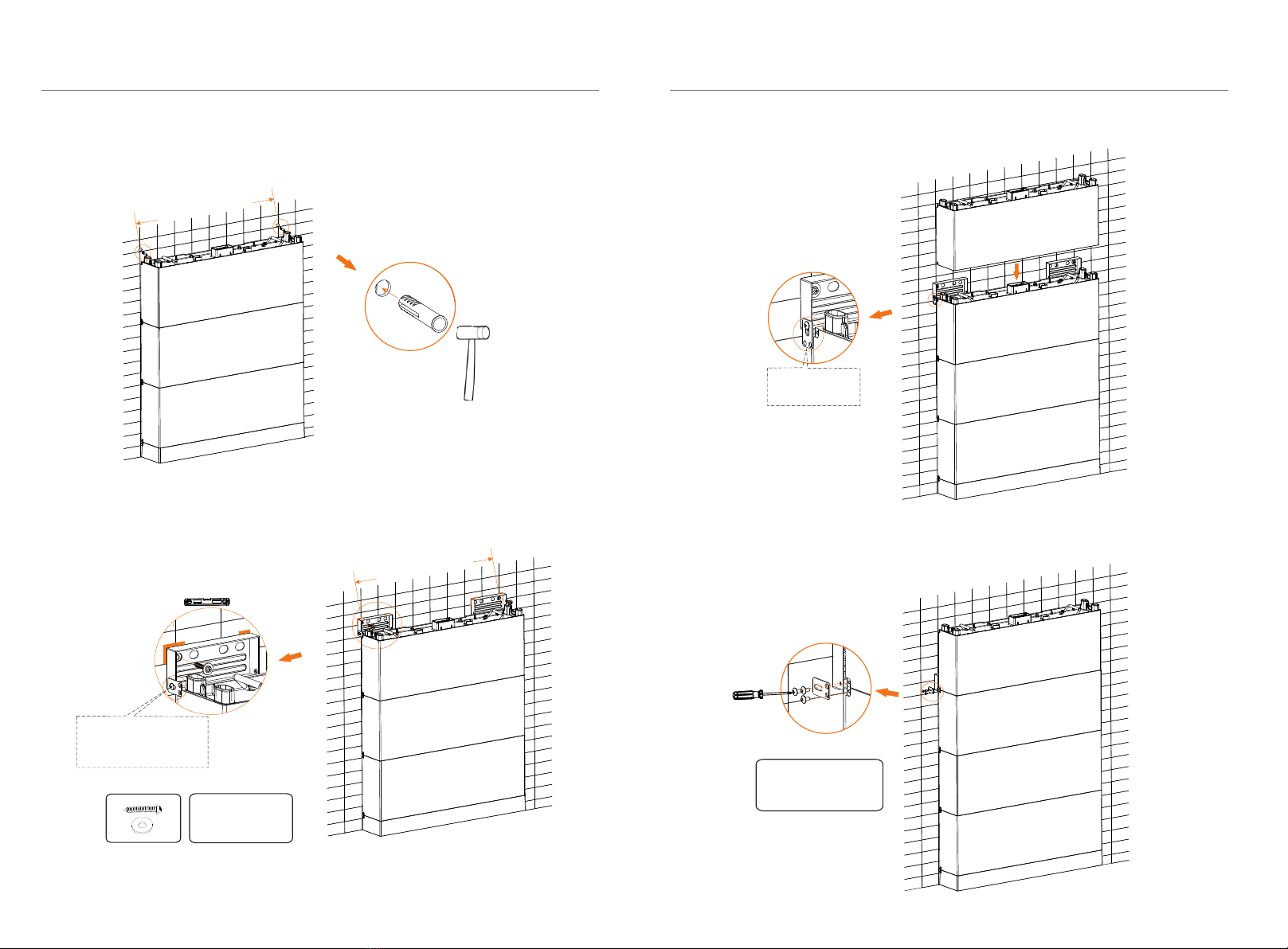
5. Installation 5. Installation
Step 6: Place Expansion Bolts into the two holes (the Expansion Bolt is not required
in case of solid wood wall).
Step 7: Place the Wall Bracket on the wall where the mark is drawn previously, and
then secure the Wall Brackets on the wall using Tapping Screws and Gaskets.
Step 8: Place the fourth battery module.
24 25
Tapping Screw × 2
Gasket × 2
Wall Bracket × 2
Attach screw but not
tighten, and align the
hole location of
battery
Let the Platen
down
Step 9: Fix the Platen (3 holes) on both sides of Battery Module using M5 * 10
Phillips-head screw, and then tighten M5*10 screws (Torque: 1.0 N·m).
Platen (3 holes) × 2
M5*10 Screw × 6
1.0 N·m
Mark
32 in./812.80 mm
32 in./812.80 mm
This manual suits for next models
3
Table of contents
Other SolaX Power Power Supply manuals


