Teleste UHC-P User manual

DVP432 User Manual, 59300088, rev004
EASITM Accessories
User Manual
Teleste Corporation
DVP432
Power Supply

DVP432 User Manual, 59300088, rev004 Contents •i
Contents
Introduction 2
General .....................................................................................................................................................2
Installation 4
Quick Instructions ....................................................................................................................................4
Mechanical Installation ............................................................................................................................5
Connectors................................................................................................................................................5
Indicators..................................................................................................................................................6
Using several DVP’s in parallel to implement back-up ...........................................................................6
Configuring the DVP432 7
General .....................................................................................................................................................7
Establishing a Data Connection................................................................................................................7
Starting CATVisor Commander...............................................................................................................8
CATVisor Commander - Connected Window .........................................................................................9
Configuring the units using CATVisor Commander..............................................................................10
DVP432 Configuration Display 12
General ...................................................................................................................................................12
Status Page .............................................................................................................................................13
Current Values Page...............................................................................................................................15
Measured values at the moment...............................................................................................15
Min & Max Page....................................................................................................................................17
Measured maximum and minimum values ..............................................................................17
The Fans Page ........................................................................................................................................18
Fan Control ..............................................................................................................................18
The Properties Page................................................................................................................................19
Legal Declarations 20
Copyright Acknowledgements ...............................................................................................................20
Trademark Acknowledgements..............................................................................................................20

DVP432 User Manual, 59300088, rev004 Introduction •2
Introduction
General
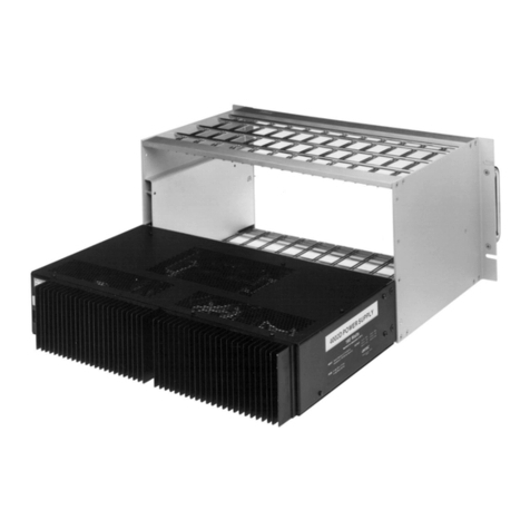
The DVP432 is a power supply for the EASITM rack
installations. It features enhanced EMC protection, output
voltage fine-tuning and stabilisation. Two logically controlled
long life fans gives the unit optimal cooling and thus further
increased reliability.
The DVP432 is using the primary switch mode technology
providing a wide input voltage range, high efficiency and
reliability. It is short circuit and over temperature protected and
it includes the PFC (Power Factor Correction). Additionally,
the outputs are diode protected to allow two or several units to
be connected in parallel to implement backup functions. The
DVP432 also features fine-tuning capabilities and enhanced
stability for all of the three output voltage circuits.
NOTE! When two or several DVP power supplies are connected in parallel
to feed a common system it is especially important that the voltages are
fine-tuned so that the currents drawn from the voltage circuit in question
spreads evenly between the feeding supplies. This can be verified by
comparing the “Current (A)” values between power supplies used. See the
configuration displays for more information.
The specified output voltages and currents per circuit are 25V /
8A, 12.5V / 5A and 6.3V / 10A. These voltages are connected
to the EASITM -system via the DVX002 installation frame, so
no connection cables are needed. If an output has overload, the
built-in current limiting function begins to take effect at 25V /
9A, 12.5V / 5.5A and 6.3V / 12A. The 12.5V and 6.3V current
is drawn from the 25V output, so note that the total maximum
available power from all 3 outlets must not exceed 200W. All
the outputs are short circuit protected.

DVP432 User Manual, 59300088, rev004 Introduction •3
The power supply has an electrical screening of class 1 and it is
intended for an indoor installation in a dry place. The unit must
not be installed in a place where it can be exposed to dripping
or splashing water. The operating voltage is 220…240 VAC,
50…60 Hz.

DVP432 User Manual, 59300088, rev004 Installation •4
Installation
Quick Instructions
•The DVP power supply unit is installed on the extreme left-
hand side of the DVX002 installation frames (positions
1&2), but it can also be installed to any other frame
position, if necessary. When the EASITM system consists of
several installation frames, each frame must have a bus
address specified (refer to the DVX002’s User Manual).
•Lock the unit into place, connect the mains power cable to a
220…240 VAC, 50…60 Hz wall outlet and see that the
green “MODULE” -indicator of the unit is lit.
•Connect a PC (with the CATVisor Commander software
installed) to the DVX BUS connector on the front panel of
the DVP power supply using the DVX021 connection
cable.
•
•Start the CATVisor Commander. See that the unit is not
indicating any alarms or warnings (Status page). Both of the
"TEMPERATURE" and "MODULE" -indicators on the
front panel should now show green.
•No programming of the power supply itself is required. The
system is now ready for installation of additional units.
Install and select the unit to configure and proceed by
filling in the required parameters according to the unit in
question.

DVP432 User Manual, 59300088, rev004 Installation •5
Mechanical Installation
Place the DVP432 power supply into a DVX002 installation
frame equipped with a specified DVX bus address (see frame
User Manual). The unit is normally placed into the first frame
position on the left-hand side, but it also can be put to any other
frame position, if necessary. Lock the module into place using
the screws on the module front panel.
Note! The unit must not be installed in a place where it is exposed to
dripping or splashing water!
Connect the mains power cable to a 220…240 VAC, 50…60
Hz wall outlet. A securing plate (included in the packing) can
be mounted to secure the connection. See that the green
“MODULE” -indicator on the front panel of the unit is lit and
that the “TEMPERATURE” -indicator also shows green. No
programming of the power supply itself is required. The system
is now ready for the installation of additional units.
Connectors
On the front panel of the unit there are RS485 and RS232
interfaces with a data bus. The RS485 (DVX BUS) -connector
is used to connect the CATVisor Commander cable DVX021 to
program the DVX units powered by the PSU, or just to monitor
the DVP power supply functions. The connection between the
CATVisor Commander (PC) and the PSU (and the EASITM
module) can also be established through a standard null-modem
cable by connecting it to the RS232 connector.
The blank F-connector on the backside of the unit has no RF-
signalling, its purpose is to enhance grounding.

DVP432 User Manual, 59300088, rev004 Installation •6
Indicators
The “MODULE” -indicator normally shows green, turning to
flashing green when software or a programmer addresses the
module. If the module have alarm(s), the indicator shows red.
The “TEMPERATURE” -indicator should also show green. If
the indicator turns to yellow, the unit temperature has already
risen above the error flag temperature (see table) and the output
power is switched off until the temperature is back to the
normal level. Possible reasons for the overheating are overload,
poor ventilation or too high environmental temperature. The
specified environmental temperature range for the power
supply unit is from -10°C to +45°C.
Ensure the sufficient supply of cooling air by installing passive
ventilation units (CVU014) or leaving at least 10 cm of free
space above and below each installation frame. The active fan
unit DVX911 can also be used if necessary.
Using several DVP’s in parallel to
implement back-up
When adding a second power supply to a EASITM system that
is already powered up and running, it is advisable to connect
the mains plug for the PSU to be added before it is inserted into
the rack. This is to ensure the stability of the other signal
processing units in the EASITM system.
When two or several DVP power supplies are connected in
parallel to feed a common system it is especially important that
the voltages are fine-tuned so that the currents drawn from the
voltage circuit in question spreads evenly between the feeding
supplies. This can be verified by comparing the “Current (A)”
values between power supplies used. See the configuration
displays for more information.

DVP432 User Manual, 59300088, rev004 Configuring the DVP432 •7
Configuring the DVP432
General
DVP units are fully controllable with the Commander
Software. The purpose of this document is to introduce the
functions of the Configuration Display of the DVP power
supplies. The Configuration Display is a part of the CATVisor
Commander software application.
Establishing a Data Connection
Connect a DVX021 -connection cable between the COM-port
of your PC and the DVX BUS -connector of a DVP power
supply. Next a connection to the EASITM module or TCP/IP
network must be established. If your PC or laptop still does not
have the CATVisor Commander software required, install the
software from the Commander installation CD. Follow the
instructions given during the installation process.

DVP432 User Manual, 59300088, rev004 Configuring the DVP432 •8
Starting CATVisor Commander
Launch Commander. When the program has started the
following Commander main view will initially appear as seen
below.
Commander Main View, new connection.
Commander is now running, but not yet connected. A
connection to the EASITM module must now be established or
reopened. To do this, choose the “File > New” or “File >
Open” commands from the pull-down menus. When making a
new connection for the first time, you may refer to the
Commander’s User Manual for the correct settings.

DVP432 User Manual, 59300088, rev004 Configuring the DVP432 •9
CATVisor Commander - Connected
Window
Configuration
Display
Tool Bar
Pull-Down
Menus
Element
Directory
Status Bar Event Log
Commander Main View, connected window.
Commander view is divided into three main sections: Element
Directory, Configuration Display and Event Log. The default
view has additionally the Pull Down Menus, the Tool Bar and
the Status Bar.
When a connection is made, a list of found units appears in the
Commander’s Element Directory on the left part of the view.
The bottom part is the Event Log, which displays all detected
events. The Configuration Display on the right part of the view
displays more detailed information on an individual unit
selected in the Element Tree Window.
The new unit should now be added to the Element Directory on
the left and listed in the bottom Event Log.

DVP432 User Manual, 59300088, rev004 Configuring the DVP432 •10
Configuring the units using
CATVisor Commander
By clicking a device, the Configuration Display will show its
configuration display pages. Each element has its own type of
configuration display pages, which include all controls and
settings that can be configured or monitored.
The Configuration Display consists of several pages; Status,
Input, …etc. Only one page is completely visible at one time.
Other pages are visible as tabs. You can activate a page simply
by clicking the tab's heading.
The Configuration Display example.
The information on configuration pages is shown in data fields
or boxes. You can change settings in data fields or boxes whose
background is white. Place your cursor in the desired data field
or box and enter the new setting. Some settings are entered by
clicking on a check box or a radio button, by selecting from a
pull-down list or by scrolling digits with the help of spin
buttons.

DVP432 User Manual, 59300088, rev004 Configuring the DVP432 •11
When you have entered a new setting, the Apply button is
activated. By clicking this button you verify the new settings
and they will be sent to the unit. If these settings are legal, they
become valid immediately and the Apply button turns inactive.
By clicking Cancel you can restore the original settings. Note
that you can change several settings before clicking Apply. If
you entered settings with the help of spin buttons, the Apply
command is not needed.
If a data field or box has a grey background, it contains read-
only information that cannot be edited. Red, yellow and blue
backgrounds of data fields or boxes indicate alarms, warnings
and notifications related to the settings or values in them.
The new settings are saved in the non-volatile memory of the
configured unit. In this way they will be maintained even if the
power is lost temporarily.
When you have finished editing, check that the configured units
are not indicating any warnings or alarms. For more
information about alarms and warnings, please see the "Status
Page".
For more detailed instructions about how to use CATVisor
Commander, please refer to its User Manual.

DVP432 User Manual, 59300088, rev004 DVP432 Configuration Display •12
DVP432 Configuration Display
General
Commander's Configuration Display consists of several pages.
Only one page is completely visible at one time. Other pages
are visible as tabs. You can activate a page simply by clicking
the tab's heading.
A DVP432 has the following Configuration Display pages that
are introduced in this document:
•Status
•Current Values
•Min & Max
•Fans
•Properties

DVP432 User Manual, 59300088, rev004 DVP432 Configuration Display •13
Status Page
The Status Page lists information messages about the status of
the DVP432. These messages can be alarms, warnings or
notifications. CATVisor Commander uses Status Flags to
represent these messages. A red flag indicates an alarm, a
yellow flag is the symbol for a warning and blue for a
notification.
Status flags and the corresponding text labels appear in the
Status field. A short description of the event is shown in the
Description field. You can also hide warnings and/or
notifications by checking the corresponding check boxes.
Alarms cannot be hidden. The Apply command is not needed
to verify these choices.
Messages are divided into the following four groups:
•Alarms concerning BIOS
•Alarms concerning Application
•Warnings concerning Application
•Notifications concerning Application

DVP432 User Manual, 59300088, rev004 DVP432 Configuration Display •14
Alarms
If an alarm is detected, the front panel “MODULE” -indicator
shows red and a red flag is in view beside the unit in
Commander's Element Directory Window.
Warning
If a warning is active a yellow flag is displayed beside the unit
in Commander's Element Directory Window.
Notifications
Notifications have an informative value only, no actions have
to be taken.
Display text Meaning Actions to correct
----------------- No application SW Update the SW using the Commander
or send the unit to service.
Calibration data
corrupted
Calibration data corrupted
(EEPROM)
Send the unit to service.
6.3 V line over
limits
Voltage outside the limits
6.05V < U < 6.55V
If too low, reduce the load. Otherwise
send unit to service.
12.5 V line over
limits
Voltage outside the limits
12.5V < U < 13.5V
If too low, reduce the load. Otherwise
send unit to service.
25 V line over
limits
Voltage outside the limits
24.0V < U < 26.0V
If too low, reduce the load. Otherwise
send unit to service.
6.3 V Overload Current drawn exceeds 10.0A. Reduce the load.
12.5 V Overload Current drawn exceeds 5.0A. Reduce the load.
25 V Overload Current drawn exceeds 8,0A. Reduce the load.
High temperature
(warning flag)
The PSU temperature is 75-85°C. Reduce the load or increase
ventilation.
Very high
temperature
(alarm)
The PSU temperature over 85°C. If
the temperature is too high the unit
will first give a warning, then an
alarm. If the temperature is still
rising the unit switches off.
Reduce the load or increase
ventilation.
Fan 1/2 fail Problem with the fan mechanics Check the fan for physical obstacles,
remove if found, otherwise send the
unit to service.
Total power error Total power consumption exceeds
200W.
Reduce the load.
Mains power
failure
Problem with mains power of PSU
in question
Check power cable
Alarm table of the DVP432.

DVP432 User Manual, 59300088, rev004 DVP432 Configuration Display •15
Current Values Page
Voltage [V]
Displays the actual voltages drawn at the moment. The
specified output voltages and currents per circuit are 25V / 8 A,
12.5V / 5A and 6.3V / 10A.
The voltages can be fine tuned using the spin buttons and the
value relative to the tuning range can be seen at the blue bar
under the voltage in question.
NOTE! When two or several DVP power supplies are connected in parallel
to feed a common system (back-up function), it is especially important that
the voltages are fine-tuned so that the currents drawn from the voltage
circuit in question spreads evenly between the feeding supplies. This can
be verified by comparing the “Current (A)” values between power supplies
used.
Current [A]
Displays the actual currents drawn at the moment. The
specified output voltages and currents per circuit are 25V / 8 A,
12.5V / 5A and 6.3V / 10A.
Measured values at
the moment

DVP432 User Manual, 59300088, rev004 DVP432 Configuration Display •16
Power
Displays the relative power output in relation of the total
capacity of the voltage outputs. Note that the 12.5V and 6.3V
outputs use the 25V circuit so the load on them is also shown in
the 25 V line.
Temperature
The bar displays the relative PSU temperature. If the
temperature is too high the unit will first give a warning, then
an alarm. If the temperature is still rising the unit switches off.

DVP432 User Manual, 59300088, rev004 DVP432 Configuration Display •17
Min & Max Page
Voltage [V]
Displays the measured minimum and maximum voltages since
the last reset. Reset the minimum and maximum values by
pressing the “Reset MinMax” -button.
Current [A]
Displays the measured minimum and maximum currents since
the last reset. Reset the minimum and maximum values by
pressing the “Reset MinMax” -button.
Temperature
Displays the measured minimum and maximum temperatures
since the last reset. Reset the minimum and maximum values
by pressing the “Reset MinMax” -button.
Time Since Reset
Displays the time from the last reset.
Measured maximum
and minimum values

DVP432 User Manual, 59300088, rev004 DVP432 Configuration Display •18
The Fans Page
Fan control
The unit has default setting of automatic ("Auto") fan control.
The use of the automatic control is recommended. Selecting
"On" and pressing "Apply" forces the fans to ventilate at the
maximum speed all the time.
Start Temperature
When the Fan Control is enabled the user can set ("Auto") the
Start Temperature (the temperature when the fans start to
increase the rotating speed). This temperature can be set
between 20…45°C. The display fields show the capacity
(rotating speed) of the both fans. A green "FAN OK" -
notification text confirms that the fans are working properly. If
a mechanical failure occurs in the fan operation an alarm is
given and a red "FAN FAIL" is displayed (see the alarm table).
Temperature
Displays the current temperature of the PSU. If the temperature
is too high the unit will first give a warning, then an alarm. If
the temperature is still rising the unit switches off.
Fan Control

DVP432 User Manual, 59300088, rev004 DVP432 Configuration Display •19
The Properties Page
Displays the unit hardware/ software information. The unit can
be named with an alias name, which will be displayed in the
Element Directory Window.
Table of contents
