SolaX Power X3-MIC G2 Series User manual

320101040508
SolaX Power Network Technology (Zhejiang) Co., Ltd.
Copyright Declaration
The copyright of this manual belongs to SolaX Power Network Technology (Zhejiang) Co., Ltd. Any
corporation or individual should not plagiarize, partially or fully copy (including software, etc.), and
no reproduction or distribution of it in any form or by any means shall be allowed. All rights reserved.
SolaX Power Network Technology (Zhejiang) Co., Ltd. reserves the right of final interpretation.
X3-MIC G2 Series
User Manual
3 kW - 15 kW
ADD.: No. 288, Shizhu Road, Tonglu Economic Development Zone,
Tonglu City, Zhejiang Province, 310000 P. R. CHINA
Tel.: +86 (0) 571-56260011
E-mail: info@solaxpower.com

Contents
Contents
1 Notes on this Manual. . . . . . . . . . . . . . . . . . . . . . . . . . . . . . . . . . . . . . . 03
1.1 Scope of Validity . . . . . . . . . . . . . . . . . . . . . . . . . . . . . . . . . . . . . . . . . . . . . . . . . . . . . . . . . . . . . . 03
1.2 Target Group. . . . . . . . . . . . . . . . . . . . . . . . . . . . . . . . . . . . . . . . . . . . . . . . . . . . . . . . . . . . . . . . . . . 03
1.3 Symbols Used . . . . . . . . . . . . . . . . . . . . . . . . . . . . . . . . . . . . . . . . . . . . . . . . . . . . . . . . . . . . . . . . . 03
2 Safety . . . . . . . . . . . . . . . . . . . . . . . . . . . . . . . . . . . . . . . . . . . . . . . . . . . . . . . 04
2.1 Appropriate Usage . . . . . . . . . . . . . . . . . . . . . . . . . . . . . . . . . . . . . . . . . . . . . . . . . . . . . . . . . . . 04
2.2 Important Safety Instructions. . . . . . . . . . . . . . . . . . . . . . . . . . . . . . . . . . . . . . . . . . . . . . . 06
2.3 Explanation of Symbols. . . . . . . . . . . . . . . . . . . . . . . . . . . . . . . . . . . . . . . . . . . . . . . . . . . . . . 08
2.4 EC Directives. . . . . . . . . . . . . . . . . . . . . . . . . . . . . . . . . . . . . . . . . . . . . . . . . . . . . . . . . . . . . . . . . . . 10
3 Introduction . . . . . . . . . . . . . . . . . . . . . . . . . . . . . . . . . . . . . . . . . . . . . . . . 11
3.1 Basic Features. . . . . . . . . . . . . . . . . . . . . . . . . . . . . . . . . . . . . . . . . . . . . . . . . . . . . . . . . . . . . . . . . . 11
3.2 Terminals of the Inverter. . . . . . . . . . . . . . . . . . . . . . . . . . . . . . . . . . . . . . . . . . . . . . . . . . . . . 11
3.3 Dimension . . . . . . . . . . . . . . . . . . . . . . . . . . . . . . . . . . . . . . . . . . . . . . . . . . . . . . . . . . . . . . . . . . . . . 12
4 Technical Data . . . . . . . . . . . . . . . . . . . . . . . . . . . . . . . . . . . . . . . . . . . . . . 13
4.1 DC Input. . . . . . . . . . . . . . . . . . . . . . . . . . . . . . . . . . . . . . . . . . . . . . . . . . . . . . . . . . . . . . . . . . . . . . . . 13
4.2 AC Output. . . . . . . . . . . . . . . . . . . . . . . . . . . . . . . . . . . . . . . . . . . . . . . . . . . . . . . . . . . . . . . . . . . . . . 14
4.3 Efficiency, Safety and Protection . . . . . . . . . . . . . . . . . . . . . . . . . . . . . . . . . . . . . . . . . . . 15
4.4 General Data. . . . . . . . . . . . . . . . . . . . . . . . . . . . . . . . . . . . . . . . . . . . . . . . . . . . . . . . . . . . . . . . . . . 16
5 Installation. . . . . . . . . . . . . . . . . . . . . . . . . . . . . . . . . . . . . . . . . . . . . . . . . . 17
5.1 Check for Transport Damage . . . . . . . . . . . . . . . . . . . . . . . . . . . . . . . . . . . . . . . . . . . . . . . 17
5.2 Packing List . . . . . . . . . . . . . . . . . . . . . . . . . . . . . . . . . . . . . . . . . . . . . . . . . . . . . . . . . . . . . . . . . . . . 17
5.3 Installation Precaution . . . . . . . . . . . . . . . . . . . . . . . . . . . . . . . . . . . . . . . . . . . . . . . . . . . . . . . 18
5.4 Installation Steps . . . . . . . . . . . . . . . . . . . . . . . . . . . . . . . . . . . . . . . . . . . . . . . . . . . . . . . . . . . . . . 19
6 Electrical Connections. . . . . . . . . . . . . . . . . . . . . . . . . . . . . . . . . . . . . . 20
6.1 PV Connection . . . . . . . . . . . . . . . . . . . . . . . . . . . . . . . . . . . . . . . . . . . . . . . . . . . . . . . . . . . . . . . . 20
6.2 Grid Connection . . . . . . . . . . . . . . . . . . . . . . . . . . . . . . . . . . . . . . . . . . . . . . . . . . . . . . . . . . . . . . 23
6.3 Earth Connection . . . . . . . . . . . . . . . . . . . . . . . . . . . . . . . . . . . . . . . . . . . . . . . . . . . . . . . . . . . . . 27
6.4 Communication Connection . . . . . . . . . . . . . . . . . . . . . . . . . . . . . . . . . . . . . . . . . . . . . . . 27
6.4.1 Monitoring Connection (Optional) . . . . . . . . . . . . . . . . . . . . . . . . . . . . . . . . . . . 27
01

1.1 Scope of Validity
This manual is an integral part of X3-MIC G2 Series. It describes the
assembly, installation, commissioning, maintenance and fault of the
product. Please read it carefully before operating.
1 Notes on this Manual
Notes on this ManualContents
X3-MIC-3K-G2 X3-MIC-4K-G2
Danger!
“Danger” indicates a hazardous situation which, if not avoided,
will result in death or serious injury.
Warning!
“Warning” indicates a hazardous situation which, if not
avoided, could result in death or serious injury.
Caution!
“Caution” indicates a hazardous situation which, if not avoided,
could result in minor or moderate injury.
Note!
“Note” provides tips that are valuable for the optimal operation
of your product.
Note: “X3” means three-phase. “MIC” is the name of the product series.
“3K” means 3 kW. “G2” means second generation. “LV” means the inveter
works in 127 V a.c. /220 V a.c. low voltage range. The products of this series
have dual MPPT inputs with DC Switch and with LCD screen.
Keep this manual at where it is accessible all the time.
X3-MIC-5K-G2
X3-MIC-8K-G2
X3-MIC-12K-G2
X3-MIC-6K-G2 X3-MIC-10K-G2
X3-MIC-15K-G2
X3-MIC-8K-G2-LVX3-MIC-6K-G2-LVX3-MIC-5K-G2-LV
02 03
6.4.2 RS485/Meter Connection. . . . . . . . . . . . . . . . . . . . . . . . . . . . . . . . . . . . . . . . . . . . . . . 28
6.4.2.1 Meter Connection (Optional) . . . . . . . . . . . . . . . . . . . . . . . . . . . . . . . . . . . . . 29
6.4.2.2 Parallel connection. . . . . . . . . . . . . . . . . . . . . . . . . . . . . . . . . . . . . . . . . . . . . . . . . . 30
6.4.2.3 EV-Charger Function. . . . . . . . . . . . . . . . . . . . . . . . . . . . . . . . . . . . . . . . . . . . . . . . 32
6.4.3 Upgrade . . . . . . . . . . . . . . . . . . . . . . . . . . . . . . . . . . . . . . . . . . . . . . . . . . . . . . . . . . . . . . . . . . . 34
6.5 Run the inverter . . . . . . . . . . . . . . . . . . . . . . . . . . . . . . . . . . . . . . . . . . . . . . . . . . . . . . . . . . . . . . . 36
7 Operation Method . . . . . . . . . . . . . . . . . . . . . . . . . . . . . . . . . . . . . . . . . 37
7.1 Control Panel . . . . . . . . . . . . . . . . . . . . . . . . . . . . . . . . . . . . . . . . . . . . . . . . . . . . . . . . . . . . . . . . . . 37
7.2 LCD Display . . . . . . . . . . . . . . . . . . . . . . . . . . . . . . . . . . . . . . . . . . . . . . . . . . . . . . . . . . . . . . . . . . . . 38
7.3 LCD Function & Operation . . . . . . . . . . . . . . . . . . . . . . . . . . . . . . . . . . . . . . . . . . . . . . . . . . 39
8 Troubleshooting. . . . . . . . . . . . . . . . . . . . . . . . . . . . . . . . . . . . . . . . . . . . 53
8.1 Troubleshooting . . . . . . . . . . . . . . . . . . . . . . . . . . . . . . . . . . . . . . . . . . . . . . . . . . . . . . . . . . . . . . 53
8.2 Routine Maintenance . . . . . . . . . . . . . . . . . . . . . . . . . . . . . . . . . . . . . . . . . . . . . . . . . . . . . . . . 56
9 Decommissioning . . . . . . . . . . . . . . . . . . . . . . . . . . . . . . . . . . . . . . . . . . 57
9.1 Dismantling the Inverter. . . . . . . . . . . . . . . . . . . . . . . . . . . . . . . . . . . . . . . . . . . . . . . . . . . . . 57
9.2 Packaging . . . . . . . . . . . . . . . . . . . . . . . . . . . . . . . . . . . . . . . . . . . . . . . . . . . . . . . . . . . . . . . . . . . . . . 57
9.3 Storage and Transportation. . . . . . . . . . . . . . . . . . . . . . . . . . . . . . . . . . . . . . . . . . . . . . . . . 57
9.4 Waste Disposal . . . . . . . . . . . . . . . . . . . . . . . . . . . . . . . . . . . . . . . . . . . . . . . . . . . . . . . . . . . . . . . . 57
10 Disclaimer . . . . . . . . . . . . . . . . . . . . . . . . . . . . . . . . . . . . . . . . . . . . . . . . . 58
* Warranty Registration Form
1.2 Target Group
This manual is for qualified electricians. The tasks described in this manual
can only be performed by qualified electricians.
1.3 Symbols Used
The following types of safety instructions and general information appear in
this document as described below:
2 Safety
2.1 Appropriate Usage
The series inverters are PV inverters which can convert the DC current of the PV
generator into AC current and feed it into the public grid.
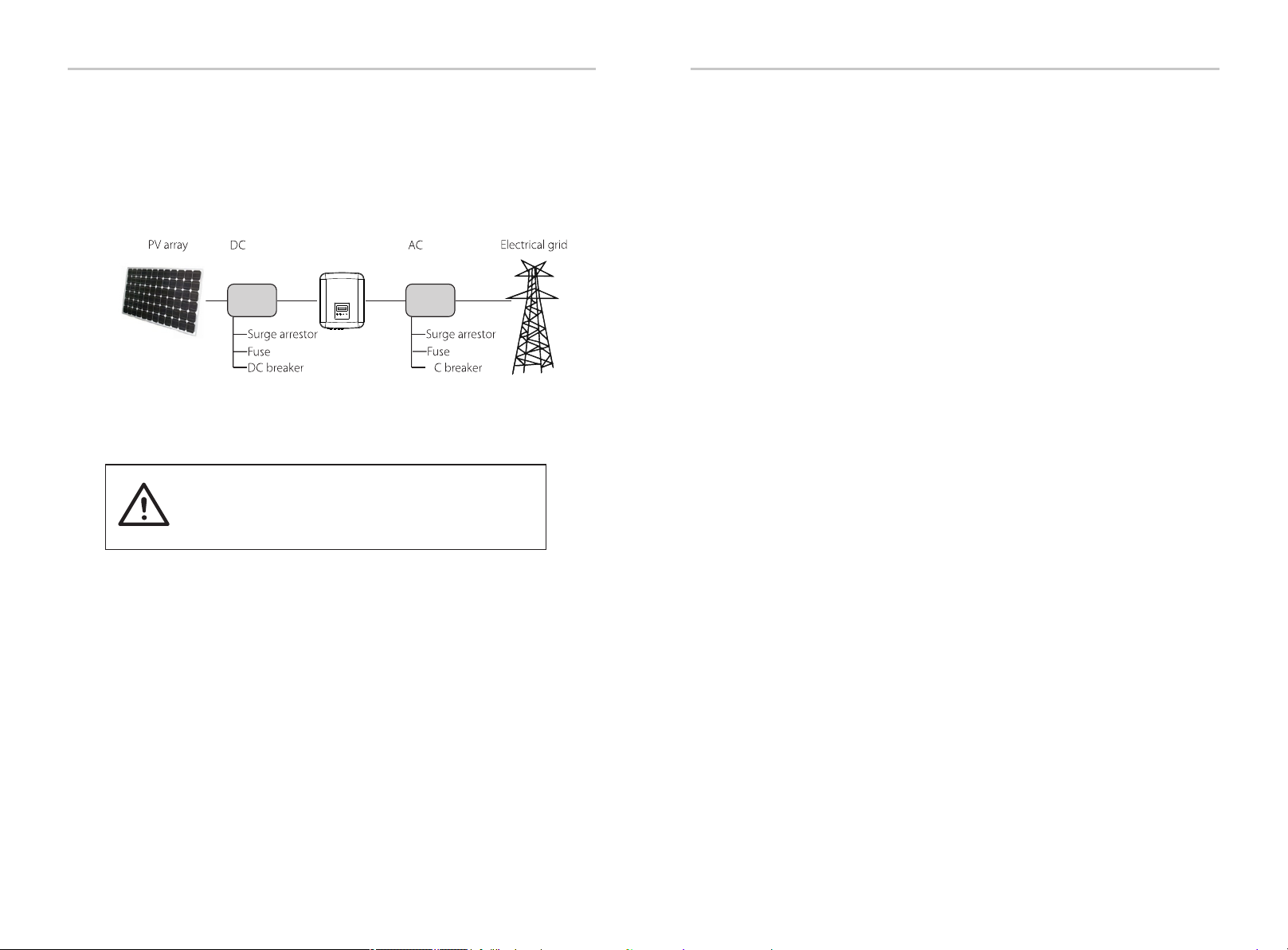
Surge protection devices (SPDs) for PV installation
Over-voltage protection with surge arresters should be
provided when the PV power system is installed.
The grid connected inverter is fitted with SPDs in both PV
input side and MAINS side.
Induced surges are the more likely cause of lightning damage in the majority of
installations, especially in rural areas where electricity is usually provided by long
overhead lines. Surges may be induced on both the PV array conductors or
the AC cables leading to the building.
Specialists in lightning protection should be consulted in the actual application.
Using appropriate external lightning protection, the effect of a direct
lightning strike into a building can be mitigated in a controlled way, and the
lightning current can be discharged into the ground.
Installation of SPDs to protect the inverter against mechanical damage and
excessive stress include a surge arrester in case of a building with external
lightning protection system (LPS) when separation distance is kept.
To protect the DC system, surge protection device (SPD type 2) should be fitted
at the inverter end of the DC cabling and at the array located between the
inverter and the PV generator.
►
SafetySafety
Anti-Islanding Effect
►
Islanding effect is a special phenomenon that grid-connected PV system still
supplies power to the nearby grid when the grid loss happened in the
power system. It is dangerous for maintenance personnel and the public.
The series inverters provide Active Frequency Drift(AFD) to prevent islanding
effect.
1
A
Distribution
Box
Distribution
Box
Inverter
gure 1
Lightning will cause a damage either from a direct strike or from surges due
to a nearby strike.
To protect the AC system, surge protection devices (SPD type2) should be
fitted at the main incoming point of AC supply (at the consumer’s
cutout), located between the inverter and the meter/distribution system;
SPD (test impulse D1) for signal line according to EN 61632-1.
All DC cables should be installed to provide as short a run as possible, and
positive and negative cables of the string or main DC supply should be
bundled together. Avoiding the creation of loops in the system. This
requirement for short runs and bundling includes any associated earth
bundling conductors.
Spark gap devices are not suitable to be used in DC circuits once
conducting, they won’t stop conducting until the voltage across their
terminals is typically below 30 volts.
Warning!
04 05

2.2 Important Safety Instructions
Danger!
Danger to life due to high voltages in the inverter!
All work must be carried out by qualified electrician.
The appliance is not to be used by children or persons with
reduced physical sensory or mental capabilities, or lack of
experience and knowledge, unless they have been given
supervision or instruction.
Children should be supervised to ensure that they do not play
with the appliance.
Caution!
Danger of burn injuries due to hot enclosure parts!
During operation, the upper lid of the enclosure and the
enclosure body may become hot.
Do not touch the metallic part of the product during operation.
Caution!
Possible damage to health as a result of the effects of radiation!
Do not stay closer than 20 cm to the inverter for a long time.
Note!
Grounding the PV generator.
Comply with the local requirements for grounding the PV
modules and the PV generator. It is recommended to connect
the generator frame and other electrically conductive surfaces
in a manner which ensures continuous conduction and ground
these in order to have optimal protection of system and persons.
Warning!
Ensure input DC voltage ≤Max. DC voltage. Over voltage
may cause permanent damage to the inverter or other
losses, which will not be included in warranty!
Warning!
Authorized service personnel must disconnect both AC and
DC power from the inverter before attempting any
maintenance or cleaning or working on any circuits connected
to the inverter.
Prior to the application, please read this section carefully to ensure correct
and safe application. Please keep the user manual properly.
Use only attachments recommended. Otherwise may result in a risk of fire,
electric shock, or injury to person.
Make sure that existing wiring is in good condition and that wire is not
undersized.
Do not disassemble any parts of the inverter which are not mentioned in
installation guide. It contains no user-serviceable parts. See Warranty for
instructions on obtaining service. Attempting to maintain the inverter by
yourself may result in a risk of electric shock or fire and will void your
warranty.
Keep away from flammable, explosive materials to avoid fire disaster.
The installation place should be away from humid or corrosive substance.
Authorized service personnel must use insulated tools when installing or
working with this equipment.
PV modules shall have an IEC 61730 class A rating.
Never touch either the positive or negative pole of PV connecting device.
Strictly prohibit touching both of them at the same time.
The unit contains capacitors that remain charged to a potentially lethal
voltage after the MAINS and PV supply has been disconnected.
Hazardous voltage will present for up to 5 minutes after disconnection from
power supply.
CAUTION - RISK of electric shock from energy stored in capacitor. Never
operate on the solar inverter couplers, the MAINS cables, PV cables or the
PV generator when power is applied. After switching off the PV and Mains,
always wait for 5 minutes to let the intermediate circuit capacitors
discharge before you unplug DC and MAINS couplers.
When accessing the internal circuit of solar inverter, it is very important to
wait 5 minutes before operating the power circuit or demounting the
electrolyte capacitors inside the device. Do not open the device before
hand since the capacitors time to sufficiently discharge! require
Measure the voltage between terminals UDC+ and UDC- with a multi-
meter (impedance at least 1Mohm) to ensure that the device is discharged
before beginning work (35 VDC) inside the device.
Safety Safety
Do not operate the inverter when the device is running.
Risk of electric shock!
Warning!
Warning!
06 07
PE Connection and Leakage Current
High leakage current!
Earth connection essential before connecting supply.
• Incorrect grounding can cause physical injury, death or equipment malfunction
and increase electromagnetic.
• Make sure that grounding conductor is adequately sized as required by safety
regulations.
• Do not connect the ground terminals of the unit in series in case of a multiple
installation. This product can cause current with a d.c. component. Where a residual
current operated protective (RCD) or monitoring (RCM) device is used for protection
in case of direct or indirect contact, only an RCD or RCM is allowed
on the supply side of this product.
For United Kingdom
• The installation that connects the equipment to the supply terminals shall
comply with the requirements of BS 7671.
• Electrical installation of PV system shall comply with requirements of BS 7671
and IEC 60364-7-712.
• No protection settings can be altered.
• User shall ensure that equipment is so installed, designed and operated to
maintain at all times compliance with the requirements of ESQCR22(1)(a).
For Australia and New Zealand
• Electrical installation and maintenance shall be conducted by licensed
electrician and shall comply with Australia National Wiring Rules.
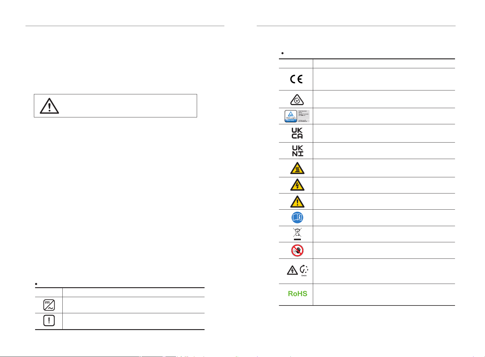
2.3 Explanation of Symbols
This section gives an explanation of all the symbols shown on the inverter and
on the type label.
Symbols on the Inverter
Symbol Explanation
Operating Display.
An error has occurred, please inform your installer immediately.
Symbols on the Type Label
Symbol Explanation
CE mark.
The inverter complies with the requirements of the applicable
CE guidelines.
RCM remark.
TUV certification.
Beware of hot surface.
The inverter can become hot during operation. Avoid contact
during operation.
Danger of high voltages.
Danger to life due to high voltages in the inverter!
Danger.
Risk of electric shock!
Observe enclosed documentation.
The inverter can not be disposed together with the household waste.
Disposal information can be found in the enclosed documentation.
Do not operate this inverter until it is isolated from mains
and on-site PV generation suppliers.
Danger to life due to high voltage.
There is residual voltage in the inverter which needs 5 min to
discharge.
• Wait 5 min before you open the upper lid or the DC lid.
Safety Safety
RoHS certificate
The inverter complies with the requirements of Restriction of
Hazardous Substances.
Compliant with UKCA standards.
Compliant with UKNI standards.
Warning!
• All inverters incorporate a certified internal Residual Current Device(RCD) in
order to protect against possible electrocution and fire hazard in case of a
malfunction in the PV array, cables or inverter. There are 2 trip thresholds for
the RCD as required for certification (IEC 62109-2:2011). The default value for
electrocution protection is 30 mA, and for slow rising current is 300 mA.
•If an external RCD is required by local regulations, it is recommended to
choose a Type-A RCD with the rating residual current of 300 mA.
08 09
This section describes the requirements of the European low voltage
regulations, including safety instructions and system licensing conditions, the
user must comply with these regulations when installing, operating, and
maintaining the inverter, otherwise personal injury or death may occur, and
the inverter will be damaged. Please read the manual carefully when
operating the inverter. If you do not understand "Danger", "Warning",
"Caution" and the descriptions in the manual, please contact the
manufacturer or service agent before installing and operating the inverter.
Make sure that the whole system complies with the requirements of
EC(2014/35/EU, 2014/30/EU, etc.) before starting the module (i.e. to start the
operation).
Standard of 2014/35/EU (LVD)
EN IEC 62109-1; EN IEC 62109-2
EN 62477-1
Standard of 2014/30/EU (EMC)
EN IEC 61000-6-1; EN IEC 61000-6-2;
EN IEC 61000-6-3; EN IEC 61000-6-4;
EN IEC 61000-3-2; EN 61000-3-3;
EN IEC 61000-3-11; EN 61000-3-12
EN 55011
The assembly shall be installed in accordance with the statutory wiring rules.
Install and configure the system in accordance with safety rules, including the
use of specified wiring methods. The installation of the system can only be
done by professional assemblers who are familiar with safety requirements
and EMC. The assembler shall ensure that the system complies with the
relevant national laws.
The individual subassembly of the system shall be interconnected by means
of the wiring methods outlined in national/international such as the national
electric code (NFPA) No. 70 or VDE regulation 4105.
3 Introduction
3.1 Basic Features
Thanks for your purchasing with the series inverter. The series inverter is
one of the finest inverters on the market today, incorporating state-of-the-
art technology, high reliability, and convenient control features.
Advanced DSP control technology.
Utilize the latest high-efficiency power component.
Optimal MPPT technology.
- Two independent MPP Tracking.
- Wide MPPT input range.
Advanced anti-islanding solutions.
IP66 protection level.
Max. efficiency up to 98.3%. EU efficiency up to 97.8%.
THDi<3%.
Safety & Reliability: transformerless design with software and hardware
protection.
Export control.
Power factor regulation.
Friendly HMI.
- LED status indications.
- LCD display technical data, human-machine interaction through press
key.
- PC remote control.
- Upgrade through USB interface.
- WiFi/LAN/4G dongle monitoring.
- Energy conservation.
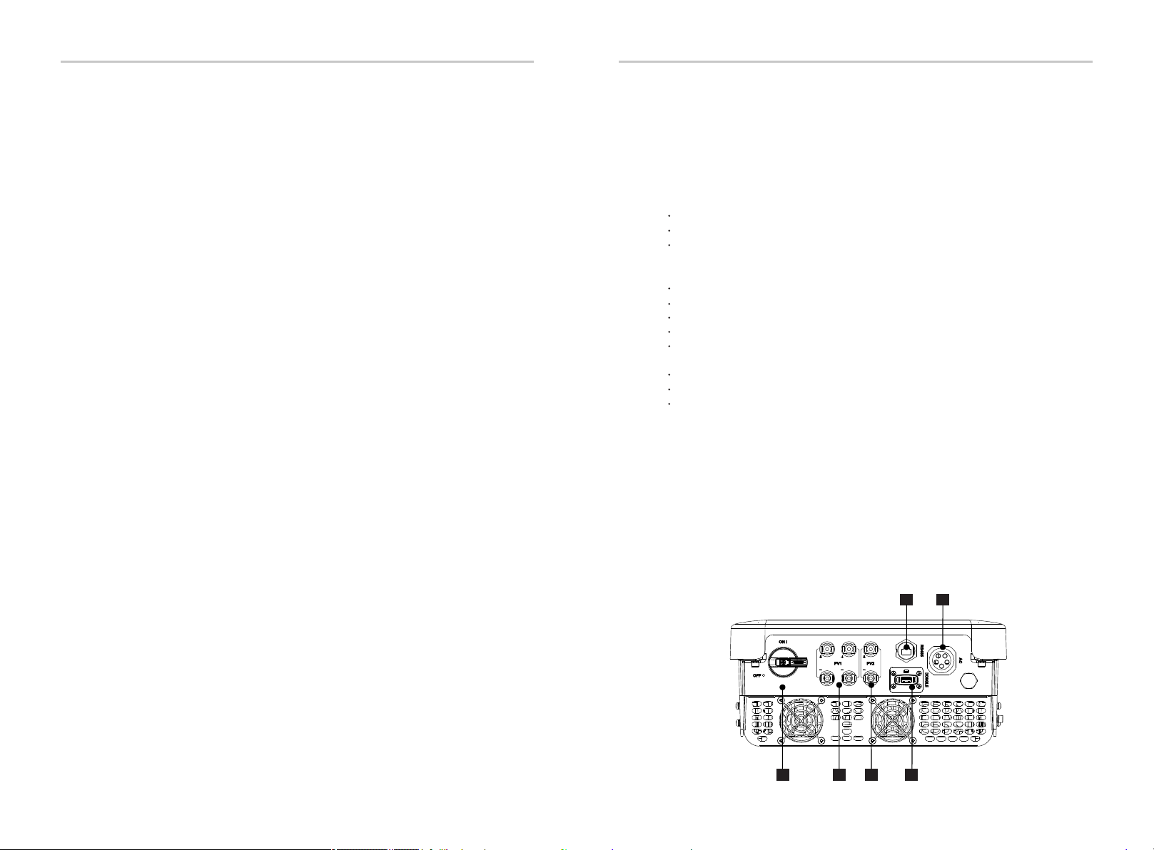
3.2 Terminals of the Inverter
Safety Introduction
A B C
FE
D
2.4 EC Directives
10 11
Warning!
Only authorized personnel is allowed to set the connection.
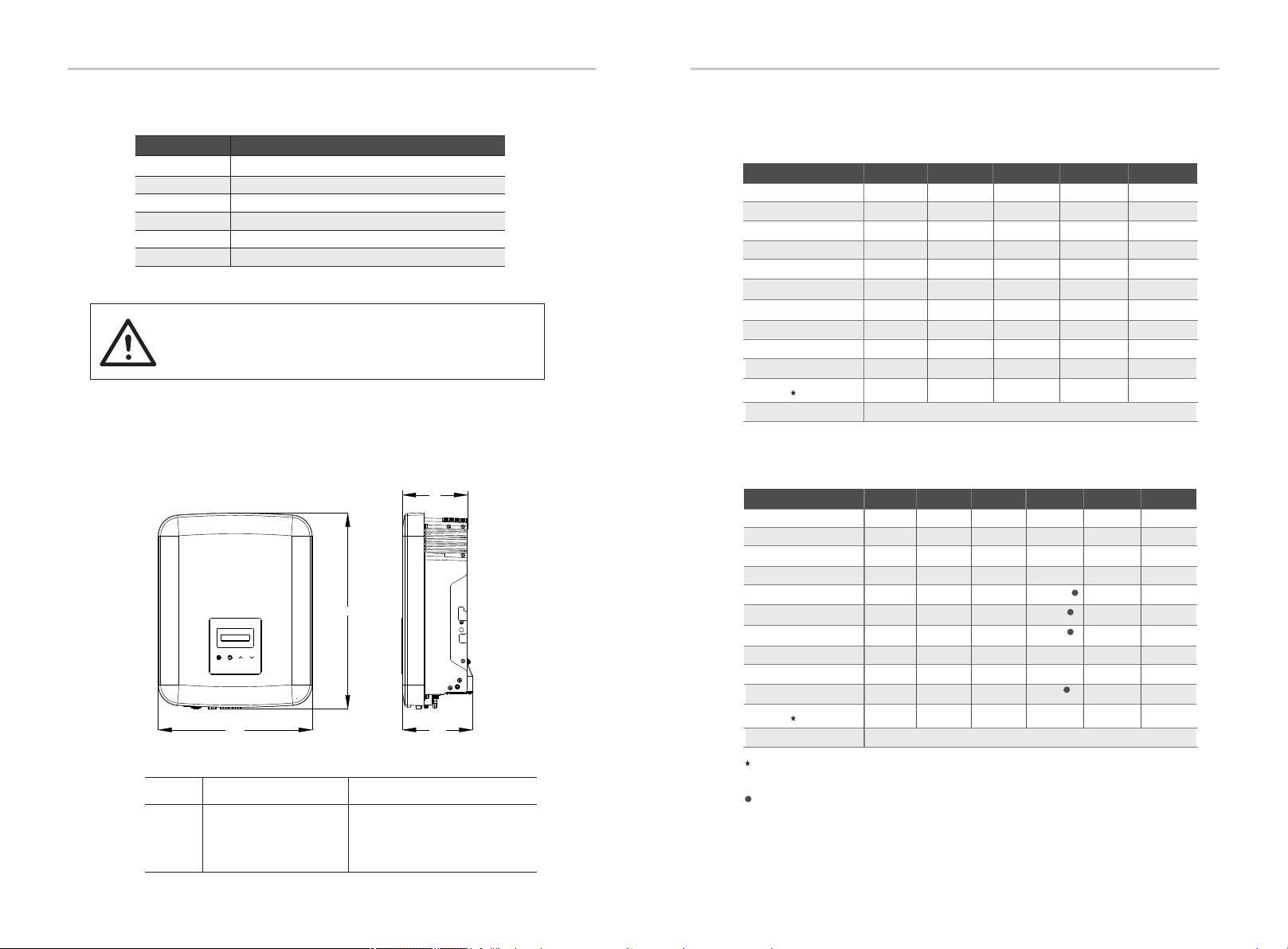
3.3 Dimension
Ø
Dimension
4 Technical Data
4.1 DC Input
12000
1000
640
120-980
260-800
16/16
20/20
150
2
1/1
16000
1000
640
120-980
315-800
16/16
20/20
150
2
1/1
20000
1000
640
120-980
395-800
16/16
20/20
150
2
1/1
Introduction Technical Data
X3-MIC-6K-G2 X3-MIC-8K-G2
Model
30000
1000
640
120-980
395-800
32/16
40/20
150
2
2/1
X3-MIC-12K-G2
24000
1000
640
120-980
315-800
32/16
40/20
150
2
2/1
X3-MIC-10K-G2 X3-MIC-15K-G2
Object
A DC Switch
PV1 Connector
AC Connector
B
C
D
E
F
Description
USB for Upgrade
PV2 Connector
Object
PV1 Connector
RS485
B
D
F
Description
DONGLE
X3-MIC-5K-G2
10000
1000
640
120-980
210-800
16/16
20/20
150
2
1/1
342 mm
434 mm
156 mm
144. 5 mm
※
※
Max. short circuit current
(input A/input B) [A]
Max. input current
(input A/input B) [A]
MPPT voltage range@ full load [V]
MPPT voltage range [V]
Nominal input voltage [V]
Max. PV input voltage [V]
Max. PV array input power [W]
Startup voltage [V]
No. of MPPT
Strings per MPPT
1
1
1
1
Input A is optional with two strings (MPPT voltage range@ full load: 300-800 V, Max. input
current: 32 A, Max. short circuit current: 40 A, Strings per MPPT: 2/1).
1
12000
800
360
120-650
260-550
16/16
20/20
150
2
1/1
16000
800
360
120-650
315-550
16/16
20/20
150
2
1/1
X3-MIC-6K-G2-LV X3-MIC-8K-G2-LV
Model
Standard
X3-MIC-5K-G2-LV
10000
800
360
120-650
210-550
16/16
20/20
150
2
1/1
DC disconnection switch
Max. short circuit current
(input A/input B) [A]
Max. input current
(input A/input B) [A]
MPPT voltage range@ full load [V]
MPPT voltage range [V]
Nominal input voltage [V]
Max. PV input voltage [V]
Max. PV array input power [W]
Startup voltage [V]
No. of MPPT
Strings per MPPT
6000
1000
640
120-980
130-800
16/16
20/20
150
2
1/1
8000
1000
640
120-980
170-800
16/16
20/20
150
2
1/1
X3-MIC-3K-G2 X3-MIC-4K-G2
Size
Model
342 mm*434 mm*144.5 mm 342 mm*434 mm*156 mm
X3-MIC-3K-G2
X3-MIC-4K-G2
X3-MIC-5K-G2
X3-MIC-8K-G2
X3-MIC-12K-G2
X3-MIC-6K-G2
X3-MIC-10K-G2
X3-MIC-15K-G2
X3-MIC-8K-G2-LV
X3-MIC-6K-G2-LV
X3-MIC-5K-G2-LV
※
12 13
Max. MPPT power limit
per MPPT [W]
Standard
DC disconnection switch
Max. MPPT power limit
per MPPT [W]
PV1: 12000
PV2: 8000
PV1: 12000
PV2: 8000
8000800060005000
400030005000 6000 8000
“Max. MPPT power limit per MPPT”means the maximum PV production when using one of
the MPPTs only.

Technical DataTechnical Data
4.2 AC Output
Max. AC output apparent power [VA]
Nominal AC voltage [V]
Nominal grid frequency [Hz]
Nominal AC output current [A]
Max. AC output current [A]
Inrush current [A]
THDi, rated power [%]
Displacement power factor
Feed-in phase
5000
5500
13.2
14.5
6000
6600
15.8
17.4
Model
27
<3%
0.8 leading ~ 0.8 lagging
Three-phase
8000
8800
21
23.1
3~/N/PE, 220/380, 230/400
X3-MIC-6K-G2-LV X3-MIC-8K-G2-LVX3-MIC-5K-G2-LV
Nominal AC output
apparent power [VA]
4.3 Efficiency, Safety and Protection
Max. AC output apparent power [VA]
Nominal AC voltage [V]
Nominal grid frequency [Hz]
Nominal AC output current [A]
Max. AC output current [A]
Inrush current [A]
THDi, rated power [%]
Displacement power factor
Feed-in phase
3000
3300
4.6/4.4
4.8
4000
4400
6.1/5.8
6.4
5000
5500
7.6/7.3
8.0
6000
6600
9.1/8.7
9.6
Model
10000
11000
15.2/14.5
16.0
27
<3%
0.8 leading ~ 0.8 lagging
Three-phase
8000
8800
12.2/11.6
12.8
3~/N/PE, 220/380, 230/400
50/60 (±5)
12000
13200
18.2/17.4
19.1
15000
15000
22.7/21.8
22.7
X3-MIC-3K-G2 X3-MIC-4K-G2
X3-MIC-6K-G2 X3-MIC-8K-G2 X3-MIC-12K-G2X3-MIC-10K-G2 X3-MIC-15K-G2X3-MIC-5K-G2
Nominal AC output
apparent power [VA]
50/60 (±5)
3~/N/PE, 127/220
MPPT efficiency
Euro efficiency
Max. efficiency
Safety & Protection
Over/under voltage protection
DC isolation protection
Grid monitoring
DC injection monitoring
Back feed current monitoring
Residual current detection
Anti-islanding protection
Over heat protection
Inverter+BMU
YES
YES
YES
YES
YES
YES
YES
YES
Model X3-MIC-6K-G2 X3-MIC-8K-G2 X3-MIC-12K-G2X3-MIC-10K-G2
X3-MIC-15K-G2
X3-MIC-5K-G2
MPPT efficiency
Euro efficiency
Max. efficiency
Safety & Protection
Over/under voltage protection
DC isolation protection
Grid monitoring
DC injection monitoring
Back feed current monitoring
Residual current detection
Anti-islanding protection
Over heat protection
Inverter+BMU
99.90%
97.80%
98.30%
YES
YES
YES
YES
YES
YES
YES
YES
Model X3-MIC-6K-G2-LV X3-MIC-8K-G2-LVX3-MIC-5K-G2-LV X3-MIC-3K-G2 X3-MIC-4K-G2
99.90%
97.80%
98.30%
14 15
Arc-fault circuit interrupter(AFCI)
AC auxiliary power supply(APS)
Optional
Optional
SPD protection YES
Arc-fault circuit interrupter(AFCI)
AC auxiliary power supply(APS)
Optional
Optional
SPD protection YES

4.4 General Data
Dimension (W/H/D)[mm]
Dimension of packing (W/H/D)[mm]
Net weight [kg]
Installation
Operating temperature range [℃]
Storage temperature [℃]
Storage/Operation relative humidity
Altitude [m]
Ingress protection
Isolation type
Protective class
Night-time consumption
Over voltage category
Pollution degree
Cooling
Noise level
Inverter topology
Communication interface
Inverter+BMU
342*434*144.5
5 Installation
5.1 Check for Transport Damage
5.2 Packing List
Make sure the inverter is intact during transportation. If there are some
visible damages, such as cracks, please contact your dealer immediately.
Open the package and fetch out the product, check the accessories at
first. The packing list is shown as below.
Object
Inverter
1
A
ABE
B
C
D
E
F
G
H
I
J
K
4/6
1
3
3
1
/
1
1
AC connector
Expansion bolt
Earth terminal
Quantity Description
Technical Data Installation
Model
Meter (Optional)
L
1
LAN dongle (Optional)
KLM
WiFi dongle (Optional)
M
J
15.5 17.015.5
4/6
H
Waterproof connector with RJ45
17.0
I
18.0 18.0
C
1
FG
D
3Self tapping screw
X3-MIC-6K-G2 X3-MIC-8K-G2 X3-MIC-12K-G2X3-MIC-10K-G2 X3-MIC-15K-G2X3-MIC-5K-G2
Round washer
<50 dB
1
Input A is optional with two strings (Net weight: 18.0 kg).
1
2*positive, 2*negative for 3 kW-8 kW and 10 kW(input A: one string)
3*positive, 3*negative for 12 kW-15 kW and 10 kW(input A: two strings)
DC connector
DC pin contact
Dimension (W/H/D)[mm]
Dimension of packing (W/H/D)[mm]
Net weight [kg]
Installation
Operating temperature range [℃]
Storage temperature [℃]
Storage/Operation relative humidity
Altitude [m]
Ingress protection
Isolation type
Protective class
Night-time consumption
Over voltage category
Pollution degree
Cooling
Noise level
Inverter topology
Communication interface
Inverter+BMU
-30~+60
Model
17.0 18.0 18.0
X3-MIC-6K-G2-LV X3-MIC-8K-G2-LVX3-MIC-5K-G2-LV
<50 dB
342*434*156
342*434*144.5
X3-MIC-3K-G2 X3-MIC-4K-G2
Wall-mounted
-30~+60 (Derating at 45)
433*515*247
0%~100%, condensation
4000 (Derating above 3000)
IP66
Class I
Transformerless
<3 W
III(MAINS), II(PV)
II(Inside), III(Outside)
USB / RS485 / DRM / WiFi/LAN/4G dongle (Optional)
Non-isolated
-30~+60
Wall-mounted
-30~+60 (Derating at 45)
0%~100%, condensation
4000 (Derating above 3000)
IP66
Class I
Transformerless
<3 W
III(MAINS), II(PV)
II(Inside), III(Outside)
Non-isolated
Natural cooling
Fan cooling
<30 dB
15.5 15.5
433*515*247
342*434*156
Fan cooling Natural cooling
<30 dB <45 dB
<45 dB
Documents
16 17
USB / RS485 / DRM / WiFi/LAN/4G dongle (Optional)
* For the optional accessories, please be subject to the actual delivery.
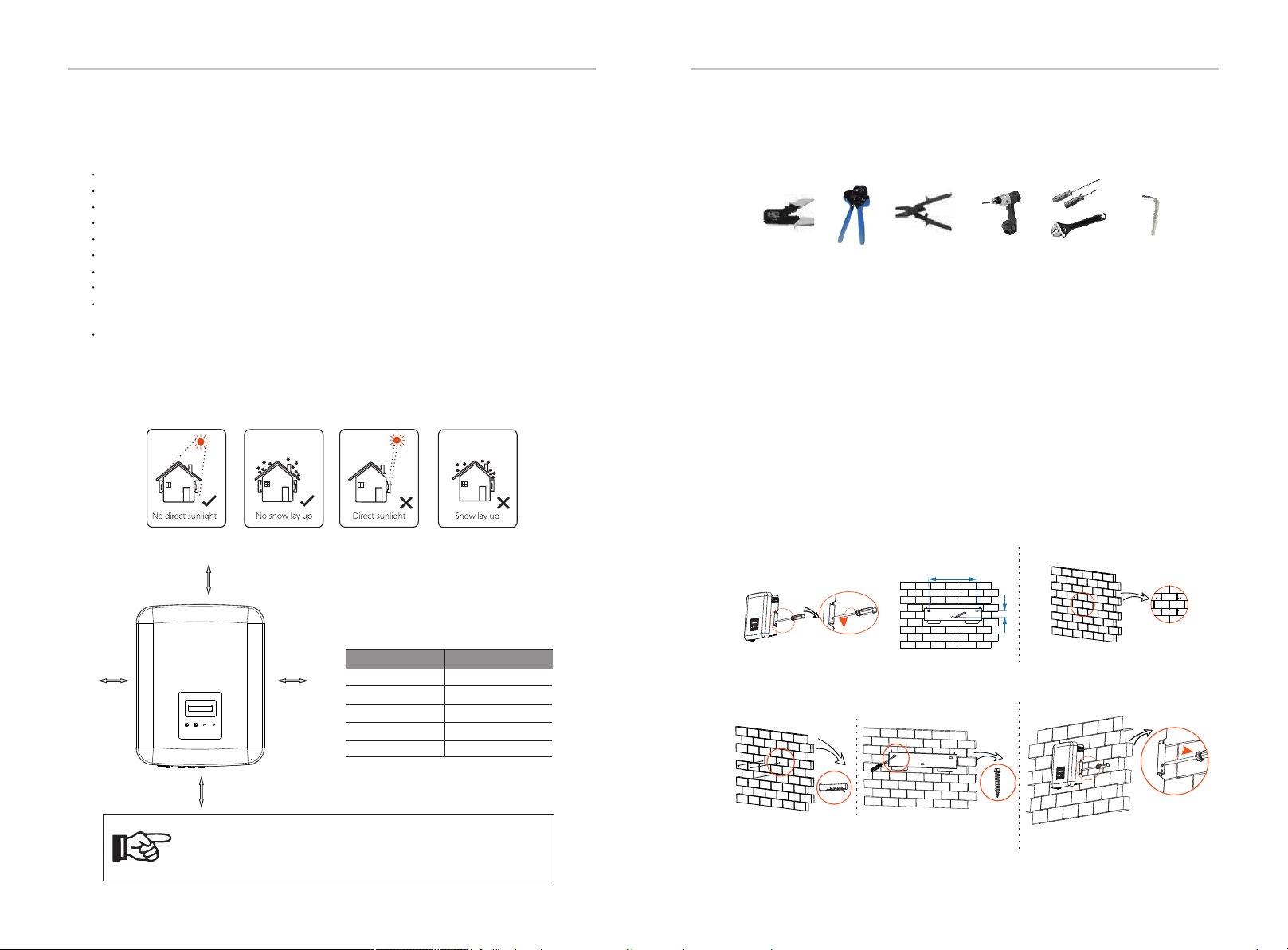
5.3 Installation Precaution
Please avoid direct sunlight, snow laying up during installing and operating.
Available Space Size
The series inverter is designed for outdoor installation (IP 66).
Make sure the installation site meets the following conditions:
Not in direct sunlight.
Not in areas where highly flammable materials are stored.
Not in potential explosive areas.
Not near the television antenna or antenna cable.
Not higher than the maximum operating altitude of the inverter.
Not in environment of precipitation or humidity.
Be sure the ventilation is good enough.
The ambient temperature in the range of -30℃ to +60℃.
The slope of the wall should be within ±5°.
Position Min. size
Ø
30 cm 30 cm Left 30 cm
30 cm
30 cm
30 cm
30 cm
Right
Top
Bottom
Front
Table: Available Space Size
30 cm
30 cm
5.4 Installation Steps
Preparation
Step 1: Screw the wall bracket on the wall
Step 2: Match the inverter with wall bracket
Ø
Ø
Ø
Below tools are needed before installation.
Installation tools : crimping plier for binding post and RJ45, wire crimper,
stripping plier, φ 10 drill, screwdrivers, manual wrench and allen wrench.
a) Unscrew the bracket from the back of the inverter. Use it as a template
to mark the position of the 3 holes (223 mm*30 mm) on the wall.
b) Drill holes with the drill, make sure the holes are deep enough (at least
60 mm) for installation.
c) Insert the expansion bolts in the holes. Then install the wall bracket by
screwing the self tapping screws.
d) Hang the inverter over the bracket, move the inverter close to it,
slightly lay down the inverter, and make sure the 2 grooves on the back of
the inverter are fixed well with the 2 lugs on the bracket. Screw the cross
recessed screw on the right side.
Installation Installation
The wall hanging the inverter should meet conditions as below:
1. solid brick/concrete, or strength equivalent mounting surface;
2. Inverter must be supported or strengthened if the wall’s strength isn’t enough
(such as wooden wall, the wall covered by thick layer of decoration).
223
30
cross screwdriver, torque: 0.8±0.1 N·m
torque: 0.8±0.1 N·m
X1
X1
a) b)
c) d)
Note!
Please do not install the inverters in parallel connection
before confirming with local installer or us. For more details,
please contact us.
18 19

The series inverters have a couple of PV connectors which can be connected in
series into 2-inputs PV modules. Please select PV modules with excellent function
and reliable quality. Open circuit voltage of module array connected should be <
Max. DC input voltage (table as below), and operating voltage should be within the
MPPT voltage range.
Table: Max. DC Voltage Limitation
Max. DC Voltage
Warning!
The voltage of PV modules is very high and dangerous, please
comply with the electric safety rules when connecting.
Warning!
Do not ground the positive or negative pole of the
photovoltaic module!
Inverter+BMU
Model
800 V
Danger!
Danger to life due to high voltage on DC conductors.
When exposed to sunlight, the PV array generates dangerous DC
voltage which is present in the DC conductors. Touching the DC
conductors can lead to lethal electric shocks.
Do not cover the PV modules.
Connection Steps
Below tools are needed before connection.
Stripping pliers Wire crimper
Wire crimper recommended model:
H4TC0001
manufacturer: Amphenol
7 mm
strip length
d) Crimp pin contact by using the wire crimper.
c) Insert stripped wire into pin contact and ensure all conductor strand are
captured in the pin contact.
pin contact
Crimp these parts
Wire crimper
a) Choose an appropriate cable (4 mm) to connect the PV module.
b) Strip 7 mm of insulation from the wire end by using the stripping pliers.
X3-MIC-6K-G2-LV X3-MIC-8K-G2-LVX3-MIC-5K-G2-LV
Note!
Please follow the requirements of PV modules as below:
Same type; Same quantity; Identical alignment; Identical tilt.
In order to save cable and reduce the DC loss, we suggest
installing the inverter near PV modules.
Max. DC Voltage Inverter+BMU
Model
980 V
X3-MIC-3K-G2 X3-MIC-4K-G2 X3-MIC-6K-G2 X3-MIC-8K-G2 X3-MIC-12K-G2X3-MIC-10K-G2 X3-MIC-15K-G2X3-MIC-5K-G2
6 Electrical Connections
6.1 PV Connection
Electrical Connections Electrical Connections
20 21
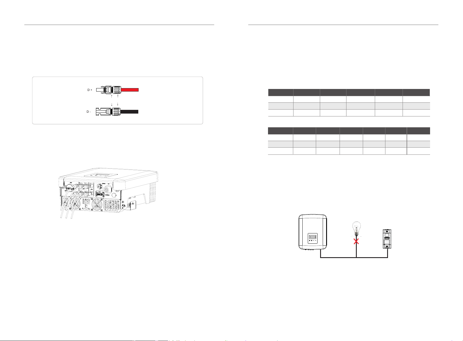
Schematic diagram of the inverter PV connected.
f ) Insert the wire into plug forcibly, when a "click” is heard or felt the pin contact
assembly is seated correctly. Then tighten the cable nut.
e) Loosen the cable nut from the DC connector. Then insert the wire with pin
contact through the cable nut.
plug cable nut
The series inverters are designed for three phase grid. For the rated grid
voltage and frequency, please refer to the section “Technical Data”. Other
technical requests should comply with the requirement of the local public
grid.
Micro-breaker should be installed between inverter and grid, any loads
should not be connected with inverter directly.
Table: Cable and Micro-breaker recommended
Incorrect Connection between Loads and Inverter
L1,L2,L3,N Cable
PE Cable
Model
*The parameters have some differences because of different environment and material.
Please choose appropriate cable and micro-breaker according to the local conditions.
5-6 mm
Micro-breaker 32 A 32 A32 A
5-6 mm5-6 mm
2.5-6 mm 2.5-6 mm 2.5-6 mm
X3-MIC-6K-G2-LV X3-MIC-8K-G2-LVX3-MIC-5K-G2-LV
L1,L2,L3,N Cable
4-5 mm
PE Cable
4-5 mm
4-5 mm5-6 mm
Model
5-6 mm
Micro-breaker
16 A 16 A
16 A 20 A 32 A 32 A 32 A32 A
5-6 mm5-6 mm5-6 mm
2.5-5 mm 2.5-5 mm
2.5-5 mm 2.5-6 mm 2.5-6 mm 2.5-6 mm 2.5-6 mm 2.5-6 mm
X3-MIC-3K-G2 X3-MIC-4K-G2
X3-MIC-6K-G2 X3-MIC-8K-G2 X3-MIC-12K-G2X3-MIC-10K-G2 X3-MIC-15K-G2X3-MIC-5K-G2
Electrical Connections Electrical Connections
6.2 Grid Connection
22 23

Connection Steps
a) Check the grid voltage and compare with the permissive voltage range (refer
to technical data).
b) Disconnect the circuit-breaker from all the phases and secure against re-
connection.
c) Strip the wires:
- Strip all the wires to 52.5 mm and the PE wire to 55 mm.
- Use the stripping pliers to strip 12 mm of insulation from wire ends as
below.
d) Seperate the AC plug into three parts as below.
- Hold the middle part of the male insert, rotate the back shell to
loosen it, and detach it from male insert.
- Remove the cable nut (with rubber insert) from the back shell.
e) Slide the cable nut and then back shell onto the cable.
f ) Insert the stripped end of the five wires into the appropriate holes of the
male insert (The N wire and PE wire must be connected correctly), and then
tighten each screw to tight each wire in place (Use the accompanying inner
hexagon spanner).
g) Tighten the screw of the back shell and the male insert.
h) Tighten the screw of the back shell and the cable nut.
L1
L2
L3
i) Align the groove of male terminal with the convex of female terminal,
then tighten the bush in male terminal.
55 mm
52.5 mm
12 mm
male insert back shell cable nut
Electrical Connections Electrical Connections
24 25
Mains cable (AC line cable) shall be short-circuit protected and thermal overload
protected.
Always fit the input cable with fuse. Normal gG (US: CC or T) fuses will protect the
input cable in short circuit situation. They will also prevent damage to adjoining
equipment.
Dimension the fuses according to local safety regulations, appropriate input
voltage and the related current of the solar inverter.
AC output protected by external fuse (gG rated current 16 A/600 VAC for X3-MIC-
3K-G2/X3-MIC-4K-G2/X3-MIC-5K-G2/X3-MIC-6K-G2; 25 A/600 VAC for X3-MIC-5K-
G2-LV/X3-MIC-8K-G2/X3-MIC-10K-G2; 40 A/600 VAC for X3-MIC-6K-G2-LV/X3-
MIC-8K-G2-LV/X3-MIC-12K-G2/X3-MIC-15K-G2) provides in all live connections to
the AC supply.
The rated short-circuit breaking capacity of the above protective device shall be
at least equal to the prospective fault current at the point of installation. See
section technical data of this manual for details.
2 2
AC output cable: Cu; R, S, T, N+PE: 3*4.0 mm +4.0 mm for X3-MIC-3K-G2/X3-MIC-
2 2
4K-G2/X3-MIC-5K-G2 and 3*5.3 mm +5.3 mm for X3-MIC-5K-G2-LV/X3-MIC-6K-
2 2
G2/X3-MIC-8K-G2/X3-MIC-10K-G2, 3*6 mm +6 mm for X3-MIC-6K-G2-LV/X3-MIC-
8K-G2-LV/X3-MIC-12K-G2/X3-MIC-15K-G2 @40 ambient temperature.℃
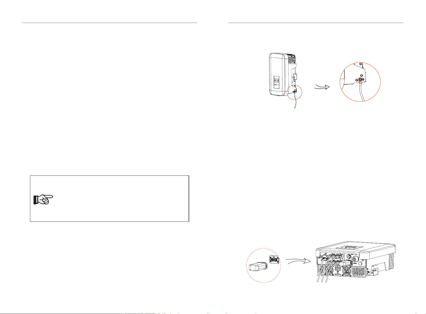
Selection of Fuses and Cables Screw allen wrench the ground screw with the shown as follows.
This product has a series of communication interfaces: such as WiFi,
RS485/Meter, DRM and USB for upgrading for human and machine
communication. Operating information like output voltage, current,
frequency, faulty information, etc., can be delivered to PC or other
monitoring equipment via these interfaces.
6.4.1 Monitoring Connection (Optional)
This inverter provides a monirtoring dongle connecting port (the DONGLE
port) which can collect information from inverter including status,
performance and updating information to the monitoring website via
connecting WiFi/LAN/4G dongle (The monitoring dongle is optional, which
can be purchased from the supplier if needed).
Connection steps(Take WiFi dongle as an example):
1. Plug the WiFi dongle into “DONGLE” port at the bottom of the inverter.
2. Connect the WiFi with router.
3. Download the monitoring APP for setting up.
4. Follow the steps to create a new account, set up internet connections
and check the inverter status.
(For more details of the monitoring configuration, please refer to the WiFi
/LAN/4G dongle user manual in the box.)
torque: 1.2±0.1 N·m
Therefore the current-carrying capacity of the components and sub-assemblies
provided in the end-use system(connectors, cables, junction box, switchgear,
etc.) and the reverse current PV modules shall be considered based on the
feedback current and reverse current. The direct current(DC) circuit breaker or
fuse between each solar generator and inverter shall be provided based on
solar inverter input ratings.
Select DC cables based on the above inverter back-feed current and ISC PV
rating and Vmax ratings.
1. For condition differing from those mentioned above,
dimension the cables according to local safety regulations,
appropriate input voltage and the load current of the unit.
(You can choose a thicker cable but the fuses must be rated
according to the rating of the cable.)
2. Fuses must be approved by Notified Body.
3. The AC output cable would be better to use the soft wire.
Note!
Electrical Connections Electrical Connections
6.3 Earth Connection
6.4 Communication Connection
26 27

There is an RS485 port on the bottom of the inverter. Through this port, the
inverter can 1) communicate with the computer, Datahub or other devices and
the meter and achieve the parallel function or EV-Charger function; or 2)
achieve multiple functions like DRM (Demand Response Management), dry
contact function and heat pump control via Adapter Box.
RS485 port of
the inverter
USB port of the
computer
RS485 to USB
•RS485 Connection Steps:
1. Prepare RJ45 connector and a communication cable.
2. Strip the insulation from the communication cable.
3. Let the communication cable pass though the waterproof connector with
RJ45, then insert it into the RJ45 connector following the PIN definition rule.
Hand tighten.torque:1.2±0.1 N·mHand tighten.torque:1.5±0.1 N·m
4. Crimp the RJ45 connector with the crimping plier.
5. Insert the cable into the RS485 port of the inverter, and tighten the
waterproof connector.
6.4.2.1 Meter Connection (Optional)
1. Monitor the energy to grid and from grid throughout the whole day.
2. Achieve the export control function with a higher accuracy.
The inverter can communicate with a meter through this interface, with the
meter you can:
The smart meter must be authorized by us, any third party or
non-authorized meter may not match with the inverter.
We will not take the responsibility if the unauthorized meter is
unavailable.
Please see the Quick Installation Guide for three-phase meter for details.
Meter Connection Steps:
Note!
a) The PIN denitions of RS485/Meter interface are as below.
1
8
PIN
Definition
1 2 3 4 5 6 7 8
485_A
X485_B
X X
Electrical
grid
Electric meter,
bidirectional
Loads
Inverter
X
6.4.2 RS485/Meter Connection
•PIN Definition:
X X
b) DRM is provided to support several demand response modes by giving
control signals as below.
Pin
Definition
123 4 5678
DRM0
XX X X X
+12V X
Pin
Definition
123 4 5678
X
Heat Pump X X GND X
c) Heat Pump Controller is the controlling signal provide by the inverter to
switch on or off the SG ready heat pump via Adapter Box. The PIN definition is
as below:
X X
Electrical Connections Electrical Connections
28 29

6.4.2.2 Parallel connection
The series inverter provides the parallel connection function when connected
with Datahub, which could support at most 60 inverters to parallel in one
system and can control zero injection to the grid with a meter installed in the
main circuit. In this parallel system, the Datahub will be the master of the
system, and all the inverters are the slaves. The Datahub can communicate
with all the slave inverters.
Diagram: Parallel system with Datahub
Note!
Before operation, please make sure that the inverters meet the
following conditions:
1. All the inverters are recommended to be the same series;
2. The firmware version of all inverters shall be the same.
Otherwise, the parallel function cannot be used.
Note!
The series inverter cannot work in parallel system without
Datahub.
Note!
Before connecting the Datahub to the parallel system, please
check that the inverters' settings meet the following
conditions:
1. The “Modbus Fuction” should be “COM485”.
2. The “ParallelSetting” should be “Disable”.
3. The addresses of all the inverters in the “RS485 CommAddr”
should be different. Otherwise, please reset the RS485
communication addresses.
a) Prepare several RJ45 splitters as needed.
b) Connect on end of an RS485 communication cable with Datahub, and the
other end with one of the slave inverters via a splitter.
c) Connect all the slave inverters with each other with RS485 cables via
splitters.
d) Connect the meter with the Datahub and the mains.
ŸWiring operation
Note!
The inverter connected with the Datahub should not enable
the “ParallelSetting”.
There is no need to set the “ParallelSetting” on the inverters,
the parallel system with Datahub will start automatically.
For the details, please refer to the user manual of Datahub.
...
Datahub
~Grid
Slave 2 Slave N
Slave 1
RS485 cable
RS485 cable
AC AC AC
Meter cable
Electrical Connections Electrical Connections
30 31
Meter

6.4.2.3 EV-Charger Function
The inverter can communicate with the smart EV-Charger to form an
intelligent photovoltaic, storage and EV charging energy system, thus
maximizing the utilization of photovoltaic energy.
a) Prepare an RJ45 splitter and the splitter should be placed in a waterproof
place.
b) Connect the communication cables of the EV-Charger, the meter and the
inverter via the splitter following the PIN definition rules.
c) The communication cable connected with the inverter should be plugged
into the RS485 port of the inverter.
ŸWiring operation
Turn on the power of the entire system, enter the “Settings” page of the
inverters on the LCD screen.
a) Enter the “Export Control” page and choose “Meter”.
ŸLCD setting
Mode Select
Meter
Export Control
DRM Function
Diagram: Intelligent Photovoltaic, Storage and EV Charging Energy System
Modbus Function
Function Select
EV Charger
b) Enter “Modbus Fuction” and select “EV Charger”.
c) Set the “Grid Data Source” as “Inverter” in the APP of the EV-Charger.
For the installation and settings of the EV-Charger, please refer to the user
manual of the EV-Charger for details.
Note!
The EV-Charger function and the parallel system with Datahub
cannot be used at the same time currently.
If the EV-Charger function is enabled and Datahub is
connected in the system, please remove the Datahub, then
the EV-Charger will work normally. If the Datahub is to be
remained in the parallel system, remove the Datahub first and
change “EV Charger” to “COM485” under the “Modbus Fuction”,
then reconnect the Datahub.
Electrical Connections Electrical Connections
32 33
Electrical
grid
PV array
AC distribution box
Inverter
Electricity meter,
bidirectional
Meter
Splitter
485A & 485B Meter cable
RS485 cable
Loads
EV-Charger

6.4.3 Upgrade
The inverter system can be updated through an U-disk.
2) Make sure the DC switch is off and the AC is disconnected with grid.
If the WiFi dongle is connected to the port, please remove the WiFi
dongle at first.
1) Please contact our service support to get the update file, and extract
it into your U-disk as the following file path:
Make sure the directory is in accordance with above form
strictly! Do not modify the program file name! Or it may cause
the inverter to stop working!
Make sure the input voltage is more than 140 V (in good
illumination condition), or it may result in failing during updating.
“update\ \618.xxxxx.00_XXXXXXXX_ARM_Vx.xx_xxxxxxxx.usb”;ARM
“update\DSP\618.xxxxx.00_XXXXXXXX_DSP_Vx.xx_ xxxxxxxx.usb”.
Upgrade Steps:
Update
ARM
DSP
3) Then insert the U-disk into the DONGLE port on the bottom of the
inverter. Then turn on DC switch and connect the PV connector, the LCD
will show a picture as below.
During updating, don’t turn off the DC switch or
disconnect the PV connector. If the updating stopped
due to PV power failure, do not unplug the U-disk. When
the PV power supply recovers, the update will continue. If
the updating stopped due to other reasons, reinsert the
U-disk to continue the update.
5) After the upgrade is completed, please remember to turn off the DC
switch or disconnect the PV connector, then pull off the U-disk, and
connect the WiFi dongle back.
Note: Vx.xx is version number, xxxxxxxx is file completion date.
4) Press “Up” and “Down” to select ARM or DSP. Then long press “Down”, and
select the correct update le to conrm the update. ARM and DSP shall be
updated one by one.
Electrical Connections Electrical Connections
34 35

6.5 Run the inverter
a) Check that device is fixed well on the wall.
b) Make sure all the DC breakers and AC breakers are OFF.
c) AC cable is connected to grid correctly.
d) All PV panels are connected to inverter correctly, DC connectors which are
not used should be sealed by a cover.
e) Make sure the external AC and DC connectors are connected.
f ) Turn on the DC switch to the “ON” position.
Start inverter after checking all below steps:
Start inverter
Inverter will start automatically when PV panels generate enough energy.
Check the status of LED indicators and LCD screen, the LED indicators should be
blue and the LCD screen should display the main interface.
If the LED indicators is not blue, please check the below:
- All the connections are correct.
- All the external disconnect switches are closed.
- The DC switch of the inverter is in the “ON” position.
Warning!
Power to the unit must be turned on only after installation
work has been completed. All electrical connections must
be carried out by qualied personnel in accordance with
legislation in force in the country concerned.
Note!
Please set the inverter if it is the first time to start up.
Above steps are for the regular start of the inverter. If it is the first
time to start up the inverter, you need to congure the settings
for the inverter after start-up.
7 Operation Method
7.1 Control Panel
Below is the three different states when operating, which means inverter starting
up successfully.
Waiting: Inverter is waiting to checking when DC input voltage from panels is
greater than 120 V(lowest start-up voltage) but less than 150 V(lowest operating
voltage).
Checking: Inverter will check DC input environment automatically when DC
input voltage from the PV panels exceeds 150 V and PV panels have enough
energy to start inverter.
Normal: Inverter begins to operate normally with blue light on. Meanwhile
feedback energy to grid, LCD displays present output power.
Enter the setting interface to follow the instructions when it is the rst time to
start up.
Operation Method
B
C
D
Object Name Description
E
LED
Indicator
Function
Button
Light in blue: The inverter is in normal status.
Flash in blue: The inverter is in waiting status.
Up/Back button:
Light in red: The inverter is in fault status.
Down/Enter button:
A
LCD Screen Display the information of the inverter.
Move cursor to upside or increase value.
Return from current interface or function.
Move cursor to downside or decrease value.
Conrm the selection.
A
C
B D
E
Note:
Down/Enter
Long Press
Up/Back
Go to the next menu or confirm value change
Look at the next parameter or decrease the value
Return to the previous menu or confirm function setting
Look at the previous parameter or increase the value
Key
Operation
Description
˄
˅
Short Press
Long Press
Short Press
Electrical Connections
36 37
Other manuals for X3-MIC G2 Series
2
This manual suits for next models
11
Table of contents
Other SolaX Power Power Supply manuals


