Thiele SI48-1U-16 User manual

User manual SI48-1U 0310.00.95-01.1 13/24
USER MANUAL
SI48-1U
DC POWER SYSTEM
07.08.2018
Warnings
Read all the tips and recommendations below. Failure to observe them can cause damage to the device, electric
shock, fire or serious injury.
fWhen connecting batteries, pay special attention to the polarity compatibility with the description near
the connector.
fDo not obstruct the ventilation. Provide at least free space of at least 8 cm on the sides of the device allowing
the proper ventilation. Otherwise, the device may be damaged or battery bank can be prematurely used out.
fMount the device in a place where it will not be exposed to direct sunlight.
fThe device must be powered from the mains with a protective earth terminal.
fBefore connecting the device, check the quality of all connections made.
fThe device may affect the operation of sensitive radio and television equipment located nearby.
fThe device may be operated only by authorized and trained personnel.
fThe device may only be serviced by the manufacturer's service department or specialized companies
authorized by the manufacturer.
1. SPECIFICATION................................................................................................................................................. 14
2. METHOD OF OPERATION............................................................................................................................... 17
3. INSTALLATION AND CONNECTION............................................................................................................ 20
4. OPERATION ........................................................................................................................................................ 22
5. SERVICE............................................................................................................................................................... 23
6. ADDITIONAL INFORMATION ........................................................................................................................ 24
This manual is intended for SI48-1U-8 and SI48-1U-16 type DC power system users. It includes specifi-
cation and guidelines required for operation and set-up.
The power system is compatible with 48 V rated voltage battery bank and is intended as a source of
uninterrupted power for telecommunications devices and industrial automation systems powered by 230 V, 50
Hz.
YOUR CONNECTION TO SAFETY
Thiele KG • Vorderer Weinberg 26 • D-71522 Backnang • Tel.: +49 (0)7191 3560-0 • Fax.: +49 (0)7191 3560-19 • [email protected] • www.thiele-kg.de
Thiele KG • Vorderer Weinberg 26 • D-71522 Backnang • Tel.: +49 (0)7191 3560-0 • Fax.: +49 (0)7191 3560-19 • [email protected] • www.thiele-kg.de
YOUR CONNECTION TO SAFETY
klick to
www
u-s-v
YOUR CONNECTION TO SAFETY
klick to
www
ACDC-DCDC
YOUR CONNECTION TO SAFETY
klick to
www
SYSTEME
YOUR CONNECTION TO SAFETY
klick to
www
CONTACT
YOUR CONNECTION TO SAFETY
klick to
www
CALLBACK

User manual SI48-1U 0310.00.95-01.1 14/24
1. SPECIFICATION
1.1. Intended use
SI48-1U power systems are sources ofuninterrupted DC power for exchanges, access telecommunication
systems and industrial automation systems up to 800 W with positive output bus connected to protective earth.
Devices supplied by a power system shall feature an extended 48 V supply voltage range required due to
the use of battery banks.
The power system is compatible with two battery banks (valve-regulated lead-acid battery), with floating
mode voltage and bulk charging voltage with compensation depending on ambient temperature and preset
correction factor.
The telecom chargers are made in the form of a metal cassette of the 1U height. Due to its design, the casing
is suitable for mounting inside 19"racks only.
1.2. Specification
1.2.1. Rated output parameters
Table 1
Rated parameters
Output voltage*
No-battery operation
48 V
Battery operation
54.2 V
Maximum output current
SI48
-1U-8
SI48-1U-16
8A
16 A
Operation with battery
bank
Nominal voltage (24 cells)
48 V
Nominal charging current
SI48
-1U-8
SI48-1U-16
4A
8A
Output voltage temperature compensation
-96 mV/°C
Digital communication
SI48-1U-8-2 and SI48-1U-16-2
SI48-1U-8-3 and SI48-1U-16-3
RS-232
RS-485
*at25°C
1.2.2. Electrical data
The detailed diagnostics and change of the charger settings is carried out by the manufacturer's service
personnel via a digital link located on the back side of the charger (without the need to interfere with the working
device). A user can check and change the settings by means of the manufacturer's software (optional).
Table 2
Nominal values or factory settings (default) are underlined
Input parameters
SI48-1U-8
SI48-1U-16
Supply voltage
184...230...253 V
Frequency
47 y53 Hz
Resistance to high and low supply voltage
176...265 V
Maximum voltage surge on power-up
30 A
60 A
Leakage current on protective conductor
<1.08 mA
<1.93 mA
Power factor at rated conditions
>0.95
Supply voltage testing
Yes
Maximum supply current
2.7 A
5.4 A
Electromagnetic emission
EN 61000-6-3
Electromagnetic immunity
EN 61000-6-2
Output parameters
Output voltage range
w/o battery bank
w/ battery bank*
44.0...48.0...60.0 V
40.8…54.2…57.6 V
Maximum output current (total for two outputs)
w/o battery bank
w/ battery bank
3…8…8 A
3…6.4…8 A
3…16…16 A
3…12.8…16 A
Output protection
output 1
output 2
20 A
10 A
Output fuse blow-out indication
Yes, for each fuse
Maximum power output
400 W
800 W
YOUR CONNECTION TO SAFETY
Thiele KG • Vorderer Weinberg 26 • D-71522 Backnang • Tel.: +49 (0)7191 3560-0 • Fax.: +49 (0)7191 3560-19 • [email protected] • www.thiele-kg.de
Thiele KG • Vorderer Weinberg 26 • D-71522 Backnang • Tel.: +49 (0)7191 3560-0 • Fax.: +49 (0)7191 3560-19 • [email protected] • www.thiele-kg.de
YOUR CONNECTION TO SAFETY
klick to
www
u-s-v
YOUR CONNECTION TO SAFETY
klick to
www
ACDC-DCDC
YOUR CONNECTION TO SAFETY
klick to
www
SYSTEME
YOUR CONNECTION TO SAFETY
klick to
www
CONTACT
YOUR CONNECTION TO SAFETY
klick to
www
CALLBACK

User manual SI48-1U 0310.00.95-01.1 15/24
Efficiency
rated conditions
for 50 % load
min 87%
min 86%
Accuracy of load distribution between rectifiers
-
r5%
Line regulation (no-battery bank operation)
<0.5%
Load regulation 0...100% range (no battery bank operation)
<0.5%
Broadband ripples
max. 2 mV
Narrowband ripples
effective value in the frequency range of up to 300 Hz
effective value in the range of above 1 kHz
50 mV
<7 mV
Battery bank operation (1 or 2)
Floating mode voltage (at 25qC)
46…54.2…56V
Floating mode voltage temperature compensation
0…80…-144 mV/°C
Fast charging voltage
48.0…55,7…58.0 V
Maximum battery charging current (current limiting level)
1.5…4…10 A
1.5…8…10 A
Battery charging indication
YES
Permissible current difference between the batteries - indication
0.5…1.0…5.0 A
0.5…2.0…5.0 A
Discharged battery disconnection voltage
36.0…42.0…48.0 V
Low battery voltage indication level
43.2 V
High battery voltage –indication threshold and rectifier switch off threshold
55.0…58.8…60.0 V
Voltage drop between battery bank and output
<0.5 V
Battery overload protection
30 A
Battery circuit fuse blow-out indication
YES, for each circuit
Digital communication
RS-232 link –transfer rate
57,600 b/s
RS-485 link –transfer rate
57,600 b/s
Electric parameters of the housing
Protection class
I
IP protection level
IP 20
General
Quiescent power with LVDD connected and no load.
16.5 W
Quiescent power without LVDD (at power failure current is supplied by a bat-
tery).
2.0 W
Remote indication –relay (MAINS FAULT, ALARM, WARNING)
3 switched contacts (NO and NC)
(60V/0.5A)
External two-state signal outputs EXT FLT #1, EXT FLT #2 (2 lines with posi-
tive bus potential)
5V/1mA
Sound indication
Yes
External temperature probe (standard power system equipment)
electric parameters
measured temperature range
measuring accuracy
Thermistor NTC 10 kΩ
-35...+75qC
r2qC
Digital voltmeter class
0.5
Digital ammeter class
1.0
*Specified range includes discharged battery bank voltage (end of battery operation mode) and bulk charging voltage.
1.2.3. Mechanical data
Overall dimensions (W × H × D) 483 × 45 × 270 mm
Weight:
SI48-1U-8 4.2 kg
SI48-1U-16 5.1 kg
Installation in 19” rack with guides,
4 mounting holes at front panel
A unit packaging includes:
Charger
User Manual
Certificate of quality control
Warranty Card
Temperature sensor
Plugs for connecting signaling circuits (5 pcs)
YOUR CONNECTION TO SAFETY
Thiele KG • Vorderer Weinberg 26 • D-71522 Backnang • Tel.: +49 (0)7191 3560-0 • Fax.: +49 (0)7191 3560-19 • [email protected] • www.thiele-kg.de
Thiele KG • Vorderer Weinberg 26 • D-71522 Backnang • Tel.: +49 (0)7191 3560-0 • Fax.: +49 (0)7191 3560-19 • [email protected] • www.thiele-kg.de
YOUR CONNECTION TO SAFETY
klick to
www
u-s-v
YOUR CONNECTION TO SAFETY
klick to
www
ACDC-DCDC
YOUR CONNECTION TO SAFETY
klick to
www
SYSTEME
YOUR CONNECTION TO SAFETY
klick to
www
CONTACT
YOUR CONNECTION TO SAFETY
klick to
www
CALLBACK

User manual SI48-1U 0310.00.95-01.1 16/24
In the standard version, the chargers are equipped with an RS-232 communication interface. In the case
of ordering a charger with the RS-485 interface, it is mounted instead of the RS-232. The chargers can coop-
erate with external RS-232/Ethernet converter modules, but they require a separate order and are delivered
in separate packaging containing their own set of documents.
For the remote control and operation of the charger, please, use the MERAWEX software - offered as a
separate product (not included in standard).
ALARM
WARNING
EXTFAULT
SI48-1U
CLEA R
POW ER
BATTERY
CHAR GE
MERAWEX
I
T
I
O
U
250
465
483
42.5
30.8
44.5
20
OUT2
10A
OUT1
20A
BAT2
30A
BAT1
30A
17.2
B
Fig. 5. Power system dimensions with a hole layout at front panel
1.3. Description of the operational environment
Table 3
Acceptable storage temperature
-40°C ÷ +85°C
Recommended storage temperature
+5°C ÷ +40°C
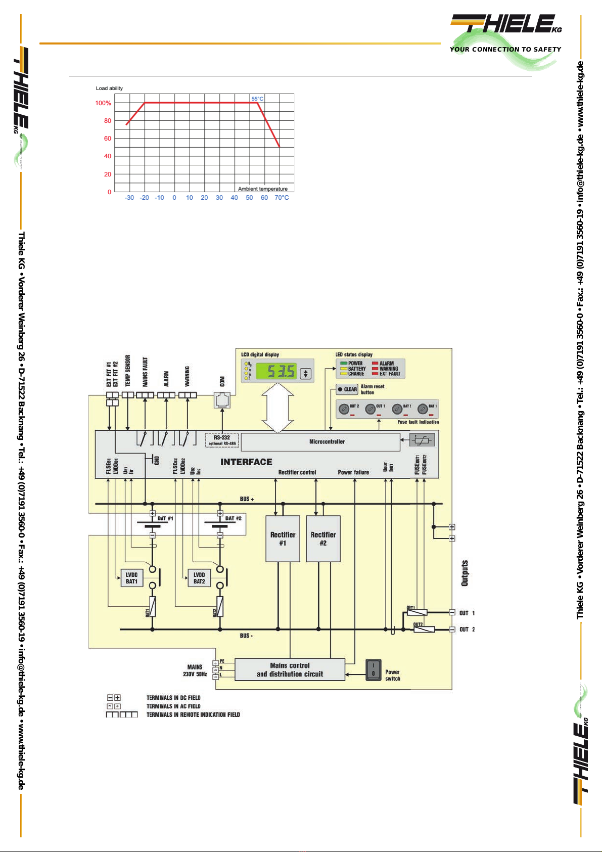
Ambient temperature during operation
(loadability of the system shown in Fig. 1)
-
33°C ÷ +55°C
Relative humidity (no condensation)
30% ÷ 80%
Atmospheric pressure
84 ÷ 107 kPa
Direct insolation
Inadmissible
Sinusoidal vibration admissible during operation:
- amplitude
- frequency
0,1 g
10 ÷ 150 Hz
Shocks during operation
Inadmissible
Vibration and shocks during transport
- amplitude
- frequency
0,5 g
10 ÷ 150 Hz
YOUR CONNECTION TO SAFETY
Thiele KG • Vorderer Weinberg 26 • D-71522 Backnang • Tel.: +49 (0)7191 3560-0 • Fax.: +49 (0)7191 3560-19 • [email protected] • www.thiele-kg.de
Thiele KG • Vorderer Weinberg 26 • D-71522 Backnang • Tel.: +49 (0)7191 3560-0 • Fax.: +49 (0)7191 3560-19 • [email protected] • www.thiele-kg.de
YOUR CONNECTION TO SAFETY
klick to
www
u-s-v
YOUR CONNECTION TO SAFETY
klick to
www
ACDC-DCDC
YOUR CONNECTION TO SAFETY
klick to
www
SYSTEME
YOUR CONNECTION TO SAFETY
klick to
www
CONTACT
YOUR CONNECTION TO SAFETY
klick to
www
CALLBACK
User manual SI48-1U 0310.00.95-01.1 17/24
Fig. 2 Load ability of the power system as a function
of ambient temperature
2. METHOD OF OPERATION
2.1.1. General
The power system is supplied by single-phase mains and generates stabilized voltage at its output(s). A
voltage on battery bank is maintained by the power system at the level of full charge depending on the type
and required value of temperature compensation. It provides battery protection against excessive discharge
that may lead to permanent damage. The power system features sound and visual indication of an operation
mode and generates alarm indications and is equipped as standard with a communication link.
2.1.2. Block diagram
Fig. 3 Block diagram of SI48-1U-16 power system
The main power blocks converting the mains voltage into stabilized output voltage are two parallel-coop-
erating rectifier blocks # 1 and # 2 –cooperating in parallel. The SI48-1U-8 charger has only one rectifier. Each
YOUR CONNECTION TO SAFETY
Thiele KG • Vorderer Weinberg 26 • D-71522 Backnang • Tel.: +49 (0)7191 3560-0 • Fax.: +49 (0)7191 3560-19 • [email protected] • www.thiele-kg.de
Thiele KG • Vorderer Weinberg 26 • D-71522 Backnang • Tel.: +49 (0)7191 3560-0 • Fax.: +49 (0)7191 3560-19 • [email protected] • www.thiele-kg.de
YOUR CONNECTION TO SAFETY
klick to
www
u-s-v
YOUR CONNECTION TO SAFETY
klick to
www
ACDC-DCDC
YOUR CONNECTION TO SAFETY
klick to
www
SYSTEME
YOUR CONNECTION TO SAFETY
klick to
www
CONTACT
YOUR CONNECTION TO SAFETY
klick to
www
CALLBACK
User manual SI48-1U 0310.00.95-01.1 18/24
of the rectifiers is a standalone power conversion block equipped with its own power factor correction (PFC)
system enabling to obtain the input cosφat a level higher than 0.95. Behind the power equalizer block, in each
rectifier, there is a DC / DC converter which reduces and stabilizes the output voltage. This converter also
provides galvanic isolation between the mains and the output circuits.
Both rectifiers cooperate in parallel, dividing output power between them. The advantage of such a solu-
tion when the load is below the nominal one is: operation of rectifiers in better conditions (lower power of the
own losses), and at low loads, operation even when one of the rectifiers is faulty. The controller monitoring
their cooperation limits the total output power to 800 W.
The power distribution packet is responsible for supplying power to the both outputs (OUT 1 and OUT 2)
of the charger from the rectifiers’ outputs (in the mains operation mode) or from the battery (in the battery
operation mode). The actual operating mode is indicated by activation of the POWER or BATTERY LED diode.
In addition, while charging the battery, this fact is indicated by the CHARGE LED being on when the bulk
charging happens or by its blinking when the charging is in the floating mode. On the packet there are two
independent LVDD devices in the both BAT 1 and BAT 2 battery circuits protecting against possible fault of
each cooperating battery. In each of the circuits (both two output circuits and two battery ones) there are fuses,
the failure of which is indicated by an individual LED diode. This signaling is also repeated by generating an
appropriate alarm, however, in the event of a blow of any of the output fuses, the general alarm, regarding the
fuse in the output circuit, is generated.
A battery test of lowering the output voltage and bringing the current from the battery is performed peri-
odically. During this time, both the acceptable voltage drop and the current difference between the batteries
are checked (if the both batteries are connected). The difference in currents between batteries is also checked
in other charger operation modes.
All alarms are signaled locally (LED diodes, LCD display and acoustic signal) and remotely via three output
signals.
The INTERFACE controls the distribution of measurement and control signals, appropriate adjustment of
their levels, distribution of power for the measurement subsystems and separation of circuits, for which the
galvanic isolation should be maintained. The basic measurement signals of voltage value UOUT,UB1,UB2 and
current value IOUT,IB1,IB2 and ambient temperatures of batteries and the interior of the charger are directed to
the INTERFACE. These signals, after reinforcement and normalization, form the basis for the evaluation of
the charger operation by its internal microprocessor controller. The controller also receives fault signals, e.g.
of each of rectifiers and fuses in the output and battery circuits.
The controller, via the INTERFACE, regulates the output voltage of the rectifiers and returns information
about their powering, internal temperature or possible fault. In addition to the operation of internal alarm sig-
nals, the system is adapted to accept two signals of external alarms (EXT FLT #1 and EXT FLT #2) requiring
shorting of contacts located on the potential of the positive rail of the charger. Consequently, the controller
issues the signals controlling signalization relays ALARM URGENT (ALARM),ALARM (WARNING), and
MAINS FAULT. These signals are provided in the form of potential-free switchable relay contacts isolated from
all other circuits, from which normally open or normally closed contacts can be used. Assigning individual
events in the charger to their signalization as an urgent alarm or non-urgent alarm, and thus making a decision
whether an event is to be acoustically signaled (only urgent alarms) is possible at the production stage or as
part of a factory service. The user can do this alone using the monitoring software sold separately.
The controller records the history of events (about 400 last ones) which has occurred in the charger,
readable via the COM communication interface, which is normally made as the RS232 port.
On the front panel there is an LCD liquid crystal display, 3½ digits, enabling the reading of the charger
parameters: output voltage, output current, battery current, temperature and alarm code (4.2.3) in case of its
occurrence. Switching between the type of displayed measurement or viewing an error number is possible by
means of the button next to the display. In addition, some alarm states (urgent alarms only) are signaled
acoustically. Canceling the acoustic alarm is possible by pressing the CLEAR button.
The socket at the back of the charger described as TEMP SENSOR allows you to connect a temperature
sensor to measure the temperature of the battery. On the basis of the measured temperature, the charger’s
controller adjusts the floating voltage of the battery bank and generates an alarm if its operating temperature
limits are exceeded. If the sensor is not connected, the charger sets the default value of floating voltage for
the temperature of 25qC and does not perform temperature compensation.
The basic, factory-set electrical settings are included in the item 1.2.3 Technical information, Electrical
parameters. The default (factory) assignments of events to the type of alarms have been described below. The
local signaling alarm codes are presented in the item 4.2.3.
2.1.3. Alarms
ALARM (indicated by a relay, ALARM LED and sound indication).
Charging (discharging) current exceeded in floating mode
YOUR CONNECTION TO SAFETY
Thiele KG • Vorderer Weinberg 26 • D-71522 Backnang • Tel.: +49 (0)7191 3560-0 • Fax.: +49 (0)7191 3560-19 • [email protected] • www.thiele-kg.de
Thiele KG • Vorderer Weinberg 26 • D-71522 Backnang • Tel.: +49 (0)7191 3560-0 • Fax.: +49 (0)7191 3560-19 • [email protected] • www.thiele-kg.de
YOUR CONNECTION TO SAFETY
klick to
www
u-s-v
YOUR CONNECTION TO SAFETY
klick to
www
ACDC-DCDC
YOUR CONNECTION TO SAFETY
klick to
www
SYSTEME
YOUR CONNECTION TO SAFETY
klick to
www
CONTACT
YOUR CONNECTION TO SAFETY
klick to
www
CALLBACK

User manual SI48-1U 0310.00.95-01.1 19/24
Maximum charging current exceeded in bulk charging mode
Maximum battery/output voltage exceeded
Battery 1 or battery 2 LVDD disconnected
Maximum battery current difference exceeded in floating mode
Maximum battery current difference exceeded in bulk charging mode
Rectifier #1 or rectifier #2 fault
Maximum output current exceeded
Output fuse (1 or 2), BAT 1 or BAT 2 fuse disconnected
External alarm 1
Power system overheating
Maximum bulk charging time exceeded
Battery loaded at power supply
Minimum voltage exceeded at battery test
Battery circuit integrity fault
Battery 1 or 2 configuration error
WARNING (indicated by a relay and WARNING LED)
Minimum voltage exceeded at battery/output
External alarm 2
Minimum permissible temperature exceeded
Maximum permissible temperature exceeded
Maximum permissible temperature exceeded at bulk charging
Temperature probe fault at the power system
Temperature probe configuration error
MAINS FAULT (indicated by a separate MAINS FAULT relay)
Events that don’t cause alarm indication:
Power failure (indicated by fading POWER LED and MAINS FAULT) relay
RTC error
2.2. Description of construction and casing
The charger is built in a metal housing of the height of 1U designed for mounting in a 19" rack. All con-
nections: mains, grounding, output circuits, battery circuits, temperature sensor, inputs and outputs of alarm
signals, and digital communication connector are located on the rear panel of the charger - therefore, it is
recommended to use cabinets that provide access from the rear.
Fig. 6. View of front panel
The front panel includes:
- mains power switch
-digital LCD display 3½ digits
- LEDs indicating type of currently displayed information
- selection key for displayed information
- diodes indicating charger operation mode
- alarm signalization diodes
- alarm cancellation button
- fuses of output and battery circuits with fault signalization diodes
Fig. 5. View of back panel
The back panel includes:
YOUR CONNECTION TO SAFETY
Thiele KG • Vorderer Weinberg 26 • D-71522 Backnang • Tel.: +49 (0)7191 3560-0 • Fax.: +49 (0)7191 3560-19 • [email protected] • www.thiele-kg.de
Thiele KG • Vorderer Weinberg 26 • D-71522 Backnang • Tel.: +49 (0)7191 3560-0 • Fax.: +49 (0)7191 3560-19 • [email protected] • www.thiele-kg.de
YOUR CONNECTION TO SAFETY
klick to
www
u-s-v
YOUR CONNECTION TO SAFETY
klick to
www
ACDC-DCDC
YOUR CONNECTION TO SAFETY
klick to
www
SYSTEME
YOUR CONNECTION TO SAFETY
klick to
www
CONTACT
YOUR CONNECTION TO SAFETY
klick to
www
CALLBACK

User manual SI48-1U 0310.00.95-01.1 20/24
- terminals for connecting battery circuits
- terminals for connecting output circuits
- socket for connecting temperature sensor
- output alarm sockets: urgent and non-urgent
- output socket of mains failure signalization
- sockets for connecting two external alarms
- digital communication socket
- ground screw terminal
- mains power terminals
3. INSTALLATION AND CONNECTION
3.1. Operation and maintenance safety
W siłowni obwody wyjściowe, obwody służące do podłączenia baterii akumulatorów oraz obwód sondy
temperaturowej sąodseparowane za pomocąizolacji wzmocnionej od obwodu wejściowego, którym jest sieć
elektroenergetyczna. Izolacja wzmocniona nie jest zbocznikowana żadnym rezystorem (grupąrezystorów),
ani żadnym kondensatorem (grupąkondensatorów).
Styki przekaźników zdalnej sygnalizacji oraz łącze COM sącałkowicie odizolowane od wszystkich obwo-
dów (także wyjściowych).
Odpowiednie wielkości wytrzymałości elektrycznej izolacji podane sąw punkcie 2.2.2.
Siłownia i jej zespoły prostownikowe zastosowane w urządzeniu wyposażone sąw kondensatory prze-
ciwzakłóceniowe klasy Y2. Prąd upływu w przewodzie ochronnym może dochodzićdo 3 mA.
UWAGA: Dla systemu telekomunikacyjnego, dodatni biegun siłowni musi byćpodłączony do metalowej kon-
strukcji obudowy:
a. bezpośrednio przez połączenie dowolnego „plusowego” zacisku śrubowego wyjścia z zaciskiem uziemie-
nia siłowni; połączenie to nie jest wykonywane fabrycznie;
b. pośrednio przez połączenie odrębnym przewodem żółto-zielonym dowolnego „plusowego” zacisku śrubo-
wego wyjścia z uziemionąszynądodatniątelekomunikacyjnej rozdzielni prądu stałego.
The power system as a class I device according to EN 60950-1 + A1 is intended for connection to a single-
phase fixed installation using a protective conductor. The device must be connected to a power network in
which protective earth is used as protection against electric shock in accordance with HD 60364-4-41
(IEC364) "Electrical installations in buildings". The metal casing of the power system is connected to the pro-
tective clamp located on its bottom plate.
In the power system, the output circuits, circuits used to connect the battery bank and the temperature probe
circuit are separated by reinforced insulation from the input circuit, which is the electrical grid. Reinforced in-
sulation is not shunted by any resistor (group of resistors) or any capacitor (group of capacitors).
The contacts of the remote signaling relays and the COM link are completely isolated from all circuits (includ-
ing output ones).
Appropriate amounts of electrical insulation resistance are given in section 2.2.2.
The power plant and its rectifier units used in the device are equipped with Y2 class anti-interference capaci-
tors. The leakage current in the protective conductor can reach 3 mA.
NOTE: For a telecommunications system, the positive pole of the gym must be connected to the metal struc-
ture of the housing:
a. Directly by connecting any "plus" output screw terminal to the gym ground terminal; this connection is not
made at the factory;
b. indirectly by connecting a separate yellow-green wire of any "plus" output screw terminal to the grounded
positive rail of the telecommunication DC switchboard.
3.2. Set-up
3.2.1. General guidelines
The power system is installed in a cabinet with 19” racks. The location of terminals at the back panel
requires use of cabinets providing an access at the back and constant access on site. Only trained service
personnel may have access to the back of the cabinet in which the charger is installed.
System features PHOENIX type screw terminals as an output, battery and mains terminals, for installation
of mains cables up to 4mm2in diameter and output and battery cables up to 6mm2in diameter. Remove 11mm
of the mains cable and 7mm of the output and battery cable insulation before installation.
YOUR CONNECTION TO SAFETY
Thiele KG • Vorderer Weinberg 26 • D-71522 Backnang • Tel.: +49 (0)7191 3560-0 • Fax.: +49 (0)7191 3560-19 • [email protected] • www.thiele-kg.de
Thiele KG • Vorderer Weinberg 26 • D-71522 Backnang • Tel.: +49 (0)7191 3560-0 • Fax.: +49 (0)7191 3560-19 • [email protected] • www.thiele-kg.de
YOUR CONNECTION TO SAFETY
klick to
www
u-s-v
YOUR CONNECTION TO SAFETY
klick to
www
ACDC-DCDC
YOUR CONNECTION TO SAFETY
klick to
www
SYSTEME
YOUR CONNECTION TO SAFETY
klick to
www
CONTACT
YOUR CONNECTION TO SAFETY
klick to
www
CALLBACK

User manual SI48-1U 0310.00.95-01.1 21/24
Remote indication circuits are connected to the PHOENIX COMBICON type terminal block. Removable
temperature probe is connected via MINI-JACK socket, digital communication utilizes RJ12 6/6 type socket.
3.2.2. Connection to the mains
You should connect a charger to the mains should be made (within the 19" rack cabinet containing the
telecommunications central unit) with the 3-wire cable of the cross-section of 1.5mm2.
NOTES:
1. The charger is not equipped with its own mains switch, therefore it is required to use an installation
switch with a function of protection against overloading and shorting, e.g. type S301 C10A in the power
circuits (outside of the charger).
2. The necessary electrical installation should be made in the form of a fixed installation equipped with
a surge protection system.
3. The circuit breaker and surge protection system should be installed in the cabinet.
Irrespective of the mains connection, enclosure shall be connected to protective earth, either locally or via
a PE protective conductor. Power system earth terminal is a M5 screw terminal - it requires min. 1.5mm2earth
conductor with ring terminal.
3.2.3. Battery installation
Power system is compatible with two 48V battery circuits connected to two terminals marked as BAT 1
and BAT 2. Each circuit is protected by a fuse located in the fuse holder at the front panel. Blown out fuses are
indicated with a LED located by the fuse holder of a specific battery circuit. The battery shall be connected
with a max. 6 mm2and a min. 4mm2conductor. Positive bus common for both battery circuits has the same
potential.
3.2.4. Load connection
SI48-1U Power system features two output circuits with terminals at the back panel marked as OUT 1 and
OUT 2. Each circuit is protected by a fuse located in the fuse holder at the front panel. Blown out fuses are
indicated with a LED located by the fuse holder of a specific output circuit. Load shall be connected with a
max. 6 mm2conductor (the limitation applies to the assembly coupling).
3.2.5. Connection of a temperature probe
SI48-1U power system provides a dependence of output voltage value in floating mode to the ambient
temperature. The end of a temperature probe is located by the battery, and the MINI-JACK socket at the other
end of a cable is connected to TEMP SENSOR (temperature probe) socket at the back panel.
3.2.6. Connection of alarm signals
Outputs marked as ALARM, WARNING and MAINS FAULT are switchable relay contacts separated from
power system circuits. Since all the sockets are connected to the relay contacts, a correct use of double pins
enables use of NO and NC contacts.
All connections require 0.5mm2y1mm2conductors with COMBICON (PHOENIX) pins.
3.2.7. Connection of external alarm signals
The power system maintains 2 external two-state signals at EXT FLT #1, EXT FLT #2 outputs, each with
the positive bus potential. Alarm is generated at a short circuit of a specific line with a positive bus. All connec-
tions require 0.5mm2y1mm2conductors with pins.
3.2.8. Connection of external communication
Back panel features 6/6 RJ12 type COM socket providing external digital communication with a power
system. Power system features RS232 module or optional RS485 module. Depending on the module used,
signals are transmitted as specified below.
Pin no.
RS-232
RS-485
1
nc
nc
2
DCD
GND
3
RxD
A
4
TxD
B
YOUR CONNECTION TO SAFETY
Thiele KG • Vorderer Weinberg 26 • D-71522 Backnang • Tel.: +49 (0)7191 3560-0 • Fax.: +49 (0)7191 3560-19 • [email protected] • www.thiele-kg.de
Thiele KG • Vorderer Weinberg 26 • D-71522 Backnang • Tel.: +49 (0)7191 3560-0 • Fax.: +49 (0)7191 3560-19 • [email protected] • www.thiele-kg.de
YOUR CONNECTION TO SAFETY
klick to
www
u-s-v
YOUR CONNECTION TO SAFETY
klick to
www
ACDC-DCDC
YOUR CONNECTION TO SAFETY
klick to
www
SYSTEME
YOUR CONNECTION TO SAFETY
klick to
www
CONTACT
YOUR CONNECTION TO SAFETY
klick to
www
CALLBACK

User manual SI48-1U 0310.00.95-01.1 22/24
Transmission parameters:
- rate 57600 b/s
- no. of data bits 8
- parity testing No
- no. of stop bits 1
Fig. 4 Digital COM socket
4. OPERATION
4.1. Power plant operation mode indication
4.1.1. Local indication
LCD displays current output voltage. Pressing the button several times changes the displayed information:
output current, battery current, temperature and information on the cause of alarm (alarm code), if present.
Another press of the button causes the output voltage to be displayed. Type of currently displayed information
is indicated by a LED on the left side of the display.
Front panel features LEDs indicating a system operation mode (POWER,BATTERY,CHARGE and alarm
event (ALARM,WARNING,EXT FAULT).
Urgent alarms are indicated by a sound indication. Sound indication is switched off by pressing CLEAR
button on the right side of LEDs. Pressing the button for more than 5 sec. causes the alarm to be reset,
although the alarm indication can be permanently reset when alarm cause is removed.
LEDs at the front panel by the fuse holders indicate blown out fuses of a specific circuit.
Details of local indication of each operation mode are presented below, and the method of alarm event
indication (local and remote) depends on the configuration - default (factory) assigned indications concerning
specific causes are presented in item 4.2.3.
Table 4
Key:
1LED/relay on
1/1 LED blinking 1 Hz
0LED/relay off
-state does not depend on the condition specified in the row
POWER
BATTERY
CHARGE
FLOATING MODE
battery charging
1
0
1/1
no-battery charging
1
0
0
BULK CHARGING
1
0
1
BATTERY OPERATION at power failure
0
1
0
Battery load at mains
1
1
0
Battery voltage below preset indication level
(battery almost discharged)
0
1/1
0
Battery discharged
0
0
0
4.1.2. Remote indication
Remote power system indication is realized by the following outputs ALARM,WARNING,MAINS FAULT.A
correct use of pins in sockets of alarm outputs, allows use of those signals as separated from other NC and
NO contacts.
Current power system operation parameters can be read using a digital socket and communication soft-
ware (optional).
4.2. General notes
All electrical parameters and alarm assignments are factory preset.
5
GND
GND
6
nc
nc
Front view - socket
1
6
YOUR CONNECTION TO SAFETY
Thiele KG • Vorderer Weinberg 26 • D-71522 Backnang • Tel.: +49 (0)7191 3560-0 • Fax.: +49 (0)7191 3560-19 • [email protected] • www.thiele-kg.de
Thiele KG • Vorderer Weinberg 26 • D-71522 Backnang • Tel.: +49 (0)7191 3560-0 • Fax.: +49 (0)7191 3560-19 • [email protected] • www.thiele-kg.de
YOUR CONNECTION TO SAFETY
klick to
www
u-s-v
YOUR CONNECTION TO SAFETY
klick to
www
ACDC-DCDC
YOUR CONNECTION TO SAFETY
klick to
www
SYSTEME
YOUR CONNECTION TO SAFETY
klick to
www
CONTACT
YOUR CONNECTION TO SAFETY
klick to
www
CALLBACK

User manual SI48-1U 0310.00.95-01.1 23/24
Detailed diagnostics and change of power system settings are carried out by a manufacturer via a digital
socket without intervention inside the device. Optional software enables diagnostics and change of power
system settings.
4.2.1. Verification of power system configuration
At power-up, power system recognizes current operation mode, i.e. detects number of connected batteries
and the presence of a temperature probe. Verification of power system configuration is confirmed by a single
audible signal.
If detected configuration differs from the default, a warning is generated (indicated by the LED at the front
panel and the remote indication socket).
4.2.2. Indication of local alarm cause
LCD displays current output voltage, and pressing the button changes the display to an output current,
battery current, temperature and alarm cause, if present.
All detected alarm events and displayed codes are indicated below.
Table 5
A: alarm; W: warning; -: inactive (external indication not activated)
Alarm
code
Description
Default set-
tings
E01
Charging (discharging) current exceeded in floating mode
A
E02
Maximum charging current exceeded in bulk charging mode
A
E03
Maximum battery/output voltage exceeded
A
E04
Minimum voltage exceeded at battery/output
W
E05
Disconnecting battery 1 LVDD
A
E06
Disconnecting battery 2 LVDD
A
E07
Maximum battery current difference exceeded in floating mode
A
E08
Maximum battery current difference exceeded in bulk charging mode
A
E09
Rectifier fault #1
A
E10
Rectifier fault #2
A
E11
Maximum output current exceeded
A
E12
Output fuse disconnected (1 or 2)
A
E13
BAT 1 fuse disconnected
A
E14
BAT 2 fuse disconnected
A
E15
External alarm 1
A
E16
External alarm 2
W
E17
Minimum permissible temperature exceeded
W
E18
Maximum permissible temperature exceeded
W
E19
Power system overheating
A
E20
Maximum permissible temperature exceeded at bulk charging
W
E21
Maximum bulk charging time exceeded
A
E22
Battery loaded at power supply
A
E23
Minimum voltage exceeded at battery test
A
E24
Battery circuit integrity fault
-
E25
Power failure
-
E26
Currently not in use
E27
Temperature probe fault at the power system
W
E28
RTC error
-
E29
Battery 1 configuration error
A
E30
Battery 2 configuration error
A
E31
Temperature probe configuration error
W
E32
Currently not in use
5. SERVICE
5.1. Maintenance and repairs
Device does not require special maintenance. Normal operation requires proper cleanness of power sys-
tem surroundings.
All warranty and post-warranty repairs are carried out by the manufacturer or specialized unit authorized
by the manufacturer.
YOUR CONNECTION TO SAFETY
Thiele KG • Vorderer Weinberg 26 • D-71522 Backnang • Tel.: +49 (0)7191 3560-0 • Fax.: +49 (0)7191 3560-19 • [email protected] • www.thiele-kg.de
Thiele KG • Vorderer Weinberg 26 • D-71522 Backnang • Tel.: +49 (0)7191 3560-0 • Fax.: +49 (0)7191 3560-19 • [email protected] • www.thiele-kg.de
YOUR CONNECTION TO SAFETY
klick to
www
u-s-v
YOUR CONNECTION TO SAFETY
klick to
www
ACDC-DCDC
YOUR CONNECTION TO SAFETY
klick to
www
SYSTEME
YOUR CONNECTION TO SAFETY
klick to
www
CONTACT
YOUR CONNECTION TO SAFETY
klick to
www
CALLBACK

User manual SI48-1U 0310.00.95-01.1 24/24
5.2. The repairs
The only components that can be replaced by a user are fuses of the battery and output circuits at the
front panel. When fuse fault is indicated by the LED it shall be replaced with a fuse of the same specification.
Fuse types are presented in the following table.
Table 6
Protected circuit
Fuse type
No.
Power system output 1 (OUT 1)
WTA 250V/6.3x32mm 20A T
1 pc
Power system output 2 (OUT 2)
WTA 250V/6.3x32mm 10A T
1 pc
Battery circuit (BAT 1 and BAT 2)
WTA 250V/6.3x32mm 30A T
2 pcs
Mains circuit*
WTA 250V/5x20mm 3.15A T
2 pcs
* fuses are inside the device and are not available for maintenance
6. ADDITIONAL INFORMATION
6.1. Manufacturer’s remarks
The manufacturer reserves the right to introduce changes in the design and technology which shall not
impair quality of the product.
6.2. Handling of the package, waste and batteries
The packaging of the product is made of materials that can be recycled (wood, paper, card-
board, plastics). Dispose of unnecessary packaging separately to the recipient of the waste mate-
rials.
This marking on the product indicates that the product should not be disposed of with municipal
waste after the expiration of its service life, but should be sent to the collection point for used elec-
tronic equipment. Waste rechargeable batteries are dangerous and must be utilized. This will
help to avoid dangerous effect on human health and the environment.
YOUR CONNECTION TO SAFETY
Thiele KG • Vorderer Weinberg 26 • D-71522 Backnang • Tel.: +49 (0)7191 3560-0 • Fax.: +49 (0)7191 3560-19 • [email protected] • www.thiele-kg.de
Thiele KG • Vorderer Weinberg 26 • D-71522 Backnang • Tel.: +49 (0)7191 3560-0 • Fax.: +49 (0)7191 3560-19 • [email protected] • www.thiele-kg.de
YOUR CONNECTION TO SAFETY
klick to
www
u-s-v
YOUR CONNECTION TO SAFETY
klick to
www
ACDC-DCDC
YOUR CONNECTION TO SAFETY
klick to
www
SYSTEME
YOUR CONNECTION TO SAFETY
klick to
www
CONTACT
YOUR CONNECTION TO SAFETY
klick to
www
CALLBACK
Table of contents
Popular Power Supply manuals by other brands

Videx
Videx 520MR Installation instruction

Poppstar
Poppstar 1008821 Instructions for use

TDK-Lambda
TDK-Lambda LZS-A1000-3 Installation, operation and maintenance manual

TDK-Lambda
TDK-Lambda 500A instruction manual

Calira
Calira EVS 17/07-DS/IU operating instructions

Monacor
Monacor PS-12CCD instruction manual


