EPS Stromversorgung PSB 9000 3U Slave series User manual

EPS
Stromversorgung
Doc ID: PSB9SEN
Revision: 01
Date: 06/2018
Operating Guide
PSB 9000 3U Slave
Bidirectional DC Power Supply


Page 3
EPS Stromversorgung GmbH
Alter Postweg 101 • 86159 Augsburg
Germany
Fon: +49 821 / 570451-0
Fax: +49 821 / 570451-25
www.eps-germany.de
info@eps-germany.de
PSB 9000 3U Slave Series
TABLE OF CONTENTS
1GENERAL
1.1 About this document......................................4
1.1.1 Retention and use..........................................4
1.1.2 Copyright........................................................4
1.1.3 Validity ............................................................4
1.1.4 Symbols and warnings ..................................4
1.2 Warranty.........................................................4
1.3 Limitation of liability ........................................4
1.4 Disposal of equipment ...................................5
1.5 Product key ....................................................5
1.6 Intended usage ..............................................5
1.7 Safety .............................................................6
1.7.1 Safety notices.................................................6
1.7.2 Responsibility of the user...............................6
1.7.3 Responsibility of the operator .......................7
1.7.4 User requirements .........................................7
1.7.5 Alarm signals..................................................8
1.8 Technical Data ...............................................8
1.8.1 Approved operating conditions......................8
1.8.2 General technical data...................................8
1.8.3 Specictechnicaldata...................................9
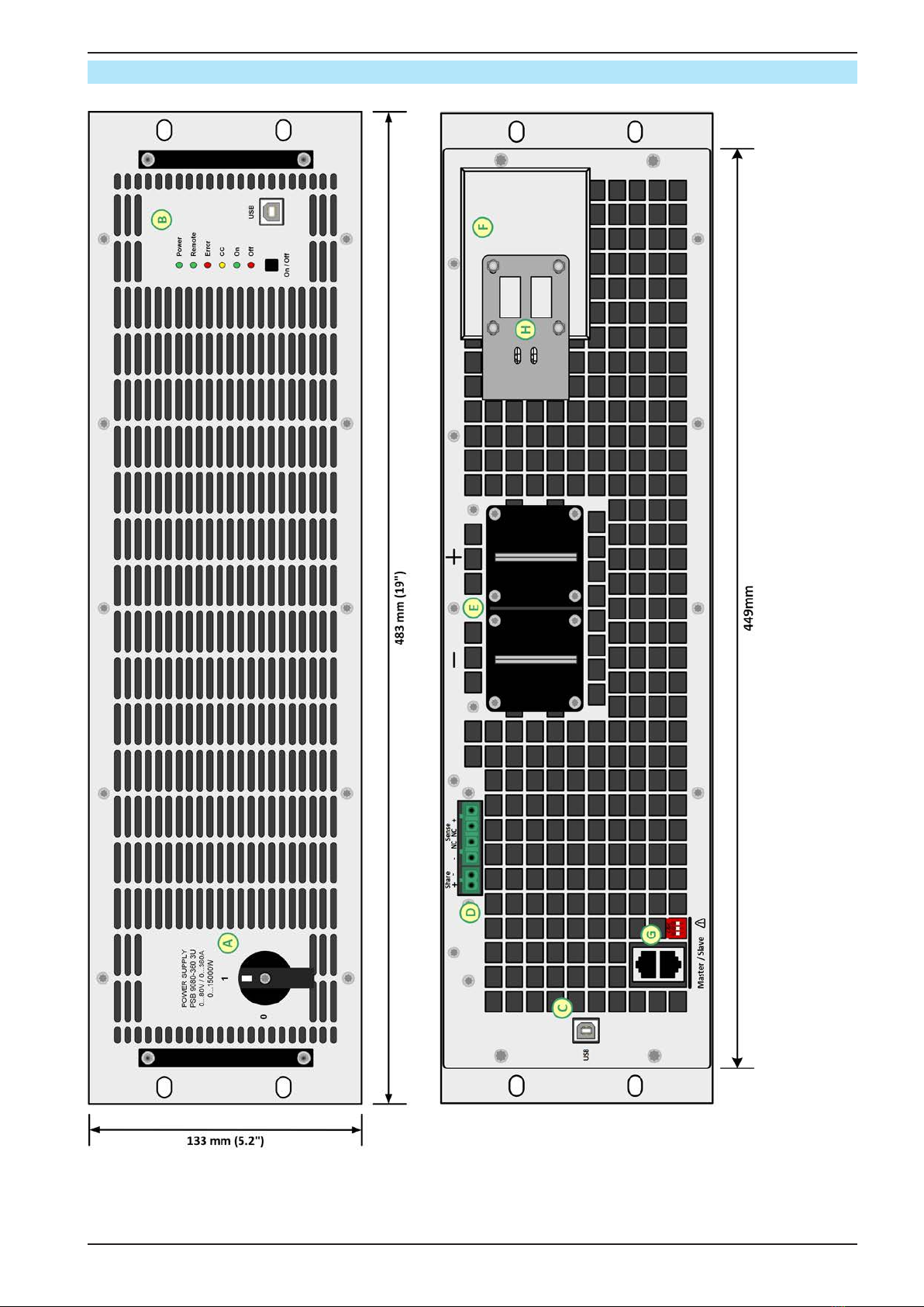
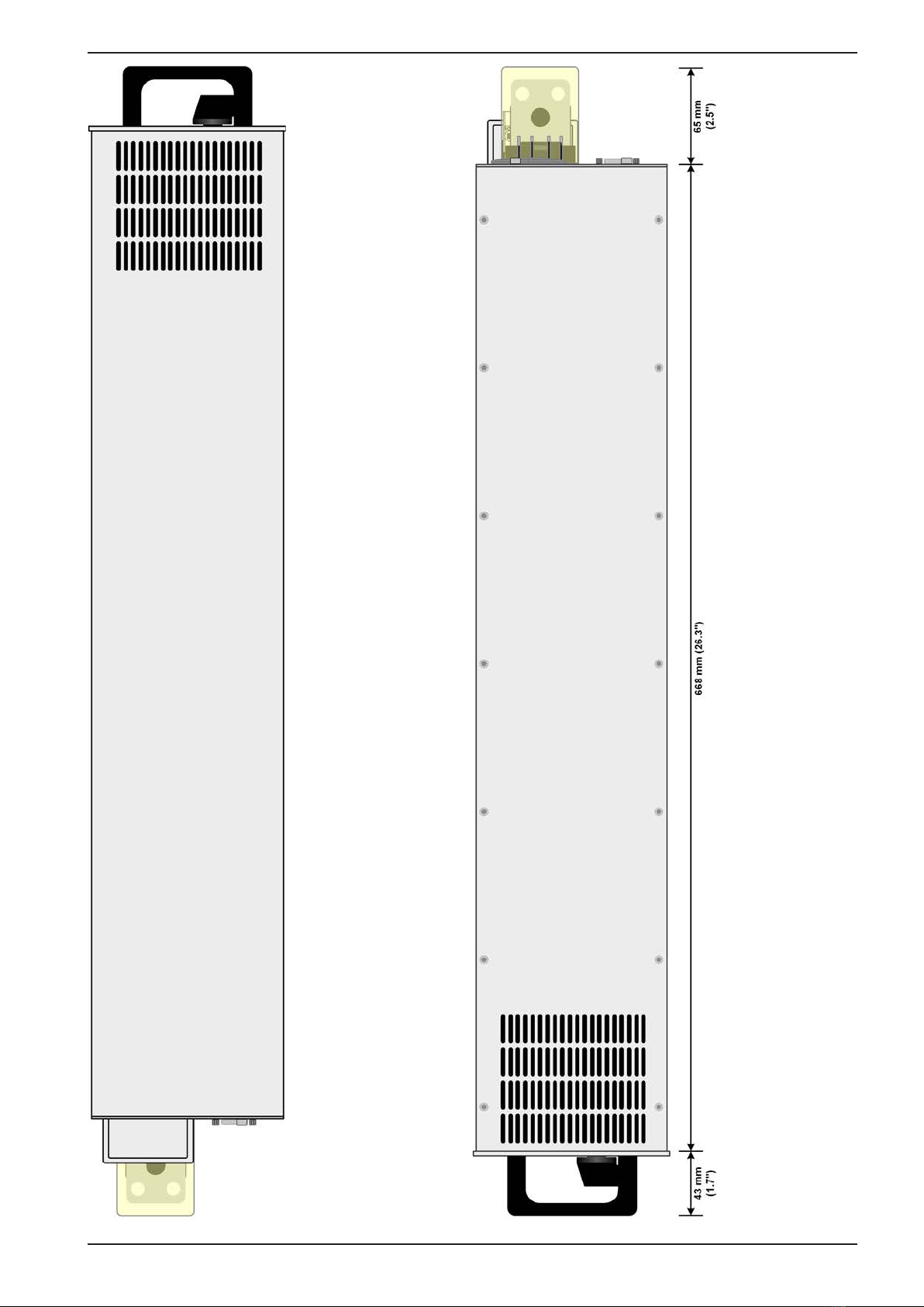
1.8.4 Views............................................................13
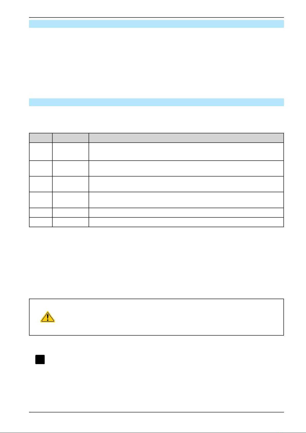
1.8.5 Control elements..........................................16
1.9 Construction and function............................17
1.9.1 General description......................................17
1.9.2 Block diagram ..............................................17
1.9.3 Scope of delivery .........................................18
1.9.4 The control panel (HMI)...............................18
1.9.5 USB port type B (rear side) .........................19
1.9.6 “Share” connector ........................................19
1.9.7 “Sense” connector (remote sensing)...........19
1.9.8 Master-Slave bus.........................................19
2INSTALLATION &
COMMISSIONING
2.1 Transport and storage .................................20
2.1.1 Transport ......................................................20
2.1.2 Packaging ....................................................20
2.1.3 Storage.........................................................20
2.2 Unpacking and visual check........................20
2.3 Installation ....................................................20
2.3.1 Safety procedures before installation and
use................................................................20
2.3.2 Preparation...................................................20
2.3.3 Installing the device .....................................22
2.3.4 Connection to AC supply .............................23
2.3.5 Connection to DC loads...............................25
2.3.6 Grounding of the DC terminal......................26
2.3.7 Connection of remote sense .......................26
2.3.8 Connecting the “Share” bus ........................27
2.3.9 Connecting the USB port.............................27
2.3.10 Initial commission.........................................28
2.3.11 Commissionafterarmwareupdateora
long period of non-use.................................28
3OPERATION AND APPLICATION
3.1 Terms............................................................29
3.2 Personal safety ............................................29
3.3 Operating modes .........................................29
3.3.1 Voltage regulation / Constant voltage .........29
3.3.2 Current regulation / constant current / current
limiting ..........................................................30
3.3.3 Power regulation / constant power / power
limiting ..........................................................30
3.3.4 Internal resistance regulation (source
mode) ...........................................................31
3.3.5 Resistance regulation / constant resistance
(sink mode) ..................................................31
3.3.6 Sink-source mode switching........................32
3.4 Alarm conditions ..........................................33
3.4.1 Power Fail ...................................................33
3.4.2 Overtemperature..........................................33
3.4.3 Overvoltage protection.................................33
3.4.4 Overcurrent protection.................................33
3.4.5 Overpower protection ..................................34
3.4.6 Safety OVP ..................................................34
3.5 Manual operation .........................................35
3.5.1 Powering the device ....................................35
3.5.2 Switchingthedeviceo...............................35
3.5.3 SwitchingtheDCterminalonoro.............35
3.6 Remote control.............................................36
3.6.1 General.........................................................36
3.6.2 Remote control via the rear USB ................36
3.6.3 Remote control via the front USB................36
3.6.4 Programming ...............................................37
3.7 Alarms and monitoring.................................38
3.7.1 Denitionofterms........................................38
3.7.2 Device alarm and event handling................38
3.8 Other applications........................................40
3.8.1 Parallel operation in master-slave (MS)......40
3.8.2 Series connection ........................................42
4SERVICE AND MAINTENANCE
4.1 Maintenance / cleaning................................43
4.2 Faultnding/diagnosis/repair...................43
4.2.1 Firmware updates ........................................43
5CONTACT AND SUPPORT
5.1 General.........................................................44
5.2 Contact options ............................................44

Page 4
EPS Stromversorgung GmbH
Alter Postweg 101 • 86159 Augsburg
Germany
Fon: +49 821 / 570451-0
Fax: +49 821 / 570451-25
www.eps-germany.de
info@eps-germany.de
PSB 9000 3U Slave Series
1. General
1.1 About this document
1.1.1 Retention and use
This document is to be kept in the vicinity of the equipment for future reference and explanation of the operation of
the device. This document is to be delivered and kept with the equipment in case of change of location and/or user.
1.1.2 Copyright
Reprinting, copying, also partially, usage for other purposes as foreseen of this manual are forbidden and breach
may lead to legal process.
1.1.3 Validity
This manual is valid for the following equipment:
Model Article nr.
PSB 9060-360 3U Slave 30090321
PSB 9080-360 3U Slave 30090312
PSB 9200-210 3U Slave 30090313
PSB 9360-120 3U Slave 30090314
PSB 9500-90 3U Slave 30090315
PSB 9750-60 3U Slave 30090316
PSB 91000-40 3U Slave 30090317
PSB 91500-30 3U Slave 30090318
1.1.4 Symbols and warnings
Warning and safety notices as well as general notices in this document are shown in a box with a symbol as follows:
Symbol for a life threatening danger
Symbol for general safety notices (instructions and damage protection bans) or important infor-
mation for operation
Symbol for general notices
1.2 Warranty
EPS Stromversorgung guarantees the functional competence of the applied technology and the stated performance
parameters. The warranty period begins with the delivery of free from defects equipment.
Terms of guarantee are included in the general terms and conditions (TOS) of EPS Stromversorgung.
1.3 Limitation of liability
All statements and instructions in this manual are based on current norms and regulations, up-to-date technology
and our long term knowledge and experience. The manufacturer accepts no liability for losses due to:
• Usage for purposes other than designed
• Use by untrained personnel
• Rebuilding by the customer
• Technical changes
• Use of not authorized spare parts
Theactualdelivereddevice(s)maydierfromtheexplanationsanddiagramsgivenhereduetolatesttechnical
changes or due to customized models with the inclusion of additionally ordered options.

Page 5
EPS Stromversorgung GmbH
Alter Postweg 101 • 86159 Augsburg
Germany
Fon: +49 821 / 570451-0
Fax: +49 821 / 570451-25
www.eps-germany.de
info@eps-germany.de
PSB 9000 3U Slave Series
1.4 Disposal of equipment
A piece of equipment which is intended for disposal must, according to European laws and regulations (ElektroG,
WEEE) be returned to the manufacturer for scrapping, unless the person operating the piece of equipment or an-
other, delegated person is conducting the disposal. Our equipment falls under these regulations and is accordingly
marked with the following symbol:
1.5 Product key
Decoding of the product description on the label, using an example:
PSB 9 080 - 360 3U Slave
Construction:
Slave = Ancillary unit for master-slave operation
3U = 3 rack units of height
Maximum current of the device in Ampere
Maximum voltage of the device in Volt
Series: 9= Series 9000
Typeidentication:
PSB = Power Supply Bidirectional
1.6 Intended usage
The equipment is intended to be used, if a power supply or battery charger, only as a variable voltage and current
source, or, if an electronic load, only as a variable current sink.
Typical application for a power supply is DC supply to any relevant user, for a battery charger the charging of vari-
ous battery types and for electronic loads the replacement of an ohmic resistor by an adjustable DC current sink
in order to load relevant voltage and current sources of any type.
• Claims of any sort due to damage caused by non-intended usage will not be accepted.
• All damage caused by non-intended usage is solely the responsibility of the operator.

Page 6
EPS Stromversorgung GmbH
Alter Postweg 101 • 86159 Augsburg
Germany
Fon: +49 821 / 570451-0
Fax: +49 821 / 570451-25
www.eps-germany.de
info@eps-germany.de
PSB 9000 3U Slave Series
1.7 Safety
1.7.1 Safety notices
Mortal danger - Hazardous voltage
• All work on connections must be carried out under zero voltage (DC terminal not con-
nected to load) and may only be performed by qualied and informed persons. Improper
actions can cause fatal injury as well as serious material damage.
• Never touch cables or connectors directly after unplugging from mains supply as the
danger of electric shock remains!
• Never touch the contacts on DC terminal terminal directly after switching o the DC
terminal, because there still can dangerous voltage present, sinking more or less slowly
depending on the load! There also can be dangerous potential between negative DC
terminal to PE or positive DC terminal to PE due to charged X capacitors.
• The equipment must only be used as intended
• The equipment is only approved for use within the connection limits stated on the product label.
• Do not insert any object, particularly metallic, through the ventilator slots
• Avoid any use of liquids near the equipment. Protect the device from wet, damp and conden-
sation.
• For power supplies and battery chargers: do not connect users, particularly low resistance, to
devices under power; sparking may occur which can cause burns as well as damage to the
equipment and to the user.
• For electronic loads: do not connect power sources to equipment under power, sparking may
occur which can cause burns as well as damage to the equipment and to the source.
• ESD regulations must be applied when plugging interface cards or modules into the relative slot
• Interfacecardsormodulesmayonlybeattachedorremovedafterthedeviceisswitchedo.
It is not necessary to open the device.
• Do not connect external power sources with reversed polarity to DC input or outputs! The
equipment will be damaged.
• For power supply devices: avoid where possible connecting external power sources to the DC
output, and never those that can generate a higher voltage than the nominal voltage of the device.
• For electronic loads: do not connect a power source to the DC input which can generate a volt-
age more than 120% of the nominal input voltage of the load. The equipment is not protected
against over voltage and may be irreparably damaged.
• Never insert a network cable which is connected to Ethernet or its components into the master-
slave socket on the rear side of the device!
• Alwayscongurethevariousprotectingfeaturesagainstovercurrent,overpoweretc.forsensi-
tive loads to what the target application requires!
1.7.2 Responsibility of the user
The equipment is in industrial operation. Therefore the operators are governed by the legal safety regulations.
Alongside the warning and safety notices in this manual the relevant safety, accident prevention and environmental
regulations must also be applied. In particular the users of the equipment:
• must be informed of the relevant job safety requirements
• mustworktothedenedresponsibilitiesforoperation,maintenanceandcleaningoftheequipment
• before starting work must have read and understood the operating manual
• must use the designated and recommended safety equipment.
Furthermore, anyone working with the equipment is responsible for ensuring that the device is at all times techni-
callytforuse.

Page 7
EPS Stromversorgung GmbH
Alter Postweg 101 • 86159 Augsburg
Germany
Fon: +49 821 / 570451-0
Fax: +49 821 / 570451-25
www.eps-germany.de
info@eps-germany.de
PSB 9000 3U Slave Series
1.7.3 Responsibility of the operator
Operator is any natural or legal person who uses the equipment or delegates the usage to a third party, and is
responsible during its usage for the safety of the user, other personnel or third parties.
The equipment is in industrial operation. Therefore the operators are governed by the legal safety regulations.
Alongside the warning and safety notices in this manual the relevant safety, accident prevention and environmental
regulations must also be applied. In particular the operator has to
• be acquainted with the relevant job safety requirements
• identifyotherpossibledangersarisingfromthespecicusageconditionsattheworkstationviaariskassessment
• introduce the necessary steps in the operating procedures for the local conditions
• regularly control that the operating procedures are current
• updatetheoperatingprocedureswherenecessarytoreectchangesinregulation,standardsoroperatingcon-
ditions.
• deneclearlyandunambiguouslytheresponsibilitiesforoperation,maintenanceandcleaningoftheequipment.
• ensure that all employees who use the equipment have read and understood the manual. Furthermore the users
are to be regularly schooled in working with the equipment and the possible dangers.
• provide all personnel who work with the equipment with the designated and recommended safety equipment
Furthermore,theoperatorisresponsibleforensuringthatthedeviceisatalltimestechnicallytforuse.
1.7.4 User requirements
Any activity with equipment of this type may only be performed by persons who are able to work correctly and
reliably and satisfy the requirements of the job.
• Personswhosereactioncapabilityisnegativelyinuencedbye.g.drugs,alcoholormedicationmaynotoperate
the equipment.
• Age or job related regulations valid at the operating site must always be applied.
Danger for unqualied users
Improper operation can cause person or object damage. Only persons who have the neces-
sary training, knowledge and experience may use the equipment.
Delegated persons are those who have been properly and demonstrably instructed in their tasks and the atten-
dant dangers.
Qualied persons are those who are able through training, knowledge and experience as well as knowledge of
thespecicdetailstocarryoutalltherequiredtasks,identifydangersandavoidpersonalandotherrisks.
Allworkonelectricalequipmentmayonlybeperformedbyqualiedelectricians.

Page 8
EPS Stromversorgung GmbH
Alter Postweg 101 • 86159 Augsburg
Germany
Fon: +49 821 / 570451-0
Fax: +49 821 / 570451-25
www.eps-germany.de
info@eps-germany.de
PSB 9000 3U Slave Series
1.7.5 Alarm signals
Alarm conditions, not danger situations, are signalled on the front of this slave device in form of a red LED “Error”
(also see section 1.8.4.). Because the models of this series are designed to run as slave units in a master-slave
system, the master unit will indicate alarms in its own available ways. Refer to the manual of series PSB 9000 3U
for more information about this matter.
The LED collects all of the below listed alarm situations. If there is supervision of the slave units being used, alarms
can be decoded by querying a status from the device via any of the two USB ports.
Global meaning of alarm situations as indicated by LED “Error”:
Signal OT
(OverTemperature)
• Overheating of the device
• DCterminalwillbeswitchedo
• Non-critical
Signal OVP
(OverVoltage)
• Overvoltage shutdown of the DC terminal due to excess voltage entering the device or
generated by the device itself due to a defect
• Critical! The device and/or the load could be damaged
Signal OCP
(OverCurrent)
• Shutdown of the DC terminal due to excess of the preset limit
• Non-critical, protects the load from excessive current consumption
Signal OPP
(OverPower)
• Shutdown of the DC terminal due to excess of the preset limit
• Non-critical, protects the load from excessive power consumption
Signal PF
(Power Fail)
• DC terminal shutdown due to AC undervoltage or defect in the AC input
• Critical on overvoltage! AC input circuit could be damaged
1.8 Technical Data
1.8.1 Approved operating conditions
• Use only inside dry buildings
• Ambient temperature 0-50°C
• Operational altitude: max. 2000 m above sea level
• Max 80% relative humidity, not condensing
1.8.2 General technical data
Indication: 6x colour LEDs
Controls: 1 pushbutton
The nominal values for the device determine the maximum adjustable ranges.

Page 9
EPS Stromversorgung GmbH
Alter Postweg 101 • 86159 Augsburg
Germany
Fon: +49 821 / 570451-0
Fax: +49 821 / 570451-25
www.eps-germany.de
info@eps-germany.de
PSB 9000 3U Slave Series
1.8.3 Specic technical data
(1Relatedtothenominalvalues,theaccuracydenesthemaximumdeviationbetweenanadjustedvaluesandthetrue(actual)value.
Example:a80Vmodelhasmin.0.1%voltageaccuracy,thatis80mV.Whenadjustingthevoltageto5V,theactualvalueisallowedtodiermax.80mV,which
means it might be between 4.92 V and 5.08 V.
(2 RMS value: LF 0...300 kHz, PP value: HF 0...20MHz
15 kW
Model Slave
PSB 9060-360 PSB 9080-360 PSB 9200-210 PSB 9360-120
AC Input
Voltage range (L-L), frequency 342..528 V AC
Connection 3ph, PE 3ph, PE 3ph, PE 3ph, PE
Frequency range 45 - 65 Hz 45 - 65 Hz 45 - 65 Hz 45 - 65 Hz
Fusing (internal) 6x T16 A 6x T16 A 6x T16 A 6x T16 A
Leak current < 3.5 mA < 3.5 mA < 3.5 mA < 3.5 mA
Phase current > 0.99 > 0.99 > 0.99 > 0.99
Eciencyofenergyrecovery ≤92% ≤92% ≤93.5% ≤93.5%
DC terminal
Max. voltage UMax 60 V 80 V 200 V 360 V
Max. current IMax 360 A 360 A 210 A 120 A
Max. power PMax 15 kW 15 kW 15 kW 15 kW
Overvoltage protection range 0...66 V 0...88 V 0...220 V 0...396 V
Overcurrent protection range 0...396 A 0...396 A 0...231 A 0...132 A
Overpower protection range 0…16.5 kW 0…16.5 kW 0…16.5 kW 0…16.5 kW
Temperaturecoecientforset
valuesΔ/K Voltage / current: 100 ppm
Capacitance (approx.) 23970μF 23970μF 7560μF 1170μF
Voltage regulation (general)
Adjustment range 0...61.2 V 0...81.6 V 0...204 V 0...367.2 V
Accuracy (1 (at 23 ± 5°C) < 0.1% UMax < 0.1% UMax < 0.1% UMax < 0.1% UMax
Lineregulationat±10%ΔUAC < 0.02% UMax < 0.02% UMax < 0.02% UMax < 0.02% UMax
Remote sensing compensation Max. 5% UMax Max. 5% UMax Max. 5% UMax Max. 5% UMax
Voltage regulation (power supply)
Loadregulationat0...100%ΔIOUT < 0.05% UMax < 0.05% UMax < 0.05% UMax < 0.05% UMax
Rise time 10...90%ΔUOUT Max. 30 ms Max. 30 ms Max. 30 ms Max. 30 ms
TransienttimeafterΔIOUT < 1.5 ms < 1.5 ms < 1.5 ms < 1.5 ms
Ripple (2 < 320 mVPP
< 25 mVRMS
< 320 mVPP
< 25 mVRMS
< 300 mVPP
< 40 mVRMS
< 320 mVPP
< 55 mVRMS
Voltage regulation (el. load)
Loadregulationat0...100%ΔU < 0.05% UMax < 0.05% UMax < 0.05% UMax < 0.05% UMax
Current regulation (general)
Adjustment range 0...367.2 A 0...367.2 A 0...214.2 A 0...122.4 A
Accuracy (1 (at 23 ± 5°C) < 0.2% IMax < 0.2% IMax < 0.2% IMax < 0.2% IMax
Lineregulationat±10%ΔUAC < 0.05% IMax < 0.05% IMax < 0.05% IMax < 0.05% IMax
Current regulation (power supply)
Loadregulationat0...100%ΔUOUT < 0.15% IMax < 0.15% IMax < 0.15% IMax < 0.15% IMax
Current regulation (el. load)
Loadregulationat0...100%ΔUIN < 0.15% IMax < 0.15% IMax < 0.15% IMax < 0.15% IMax
Ripple (2 < 240 mARMS < 240 mARMS < 66 mARMS < 50 mARMS

Page 10
EPS Stromversorgung GmbH
Alter Postweg 101 • 86159 Augsburg
Germany
Fon: +49 821 / 570451-0
Fax: +49 821 / 570451-25
www.eps-germany.de
info@eps-germany.de
PSB 9000 3U Slave Series
(1Relatedtothenominalvalues,theaccuracydenesthemaximumdeviationbetweenanadjustedvaluesandthetrue(actual)value
(2 Typical value at 100% voltage and 100% power
15 kW
Model Slave
PSB 9060-360 PSB 9080-360 PSB 9200-210 PSB 9360-120
Power regulation
Adjustment range 0…15.3 kW 0…15.3 kW 0…15.3 kW 0…15.3 kW
Accuracy (1 (at 23 ± 5°C) < 1% PMax < 1% PMax < 1% PMax < 1% PMax
Lineregulationat±10%ΔUAC < 0.05% PMax < 0.05% PMax < 0.05% PMax < 0.05% PMax
Loadreg.at10-90%ΔUOUT*ΔIOUT < 0.75% PMax < 0.75% PMax < 0.75% PMax < 0.75% PMax
Eciency(2 ~ 93% ~ 93% ~ 95% ~ 94%
Internal resistance regulation
Adjustment range 0.006...10 0.006...10Ω 0.033...50Ω 0.1..180Ω
Accuracy (1 ≤2%ofmax.resistance±0.3%ofmaximumcurrent
Insulation Allowedoat(potentialshift)ontheDCterminal:
Negative terminal to PE Max. ±400 V DC ±400 V DC ±725 V DC ±725 V DC
Positive terminal to PE Max. ±400 V DC ±400 V DC ±1000 V DC ±1000 V DC
AC input <-> PE 2.5 kV DC
AC input <-> DC terminal 2.5 kV DC
Miscellaneous
Cooling Temperature controlled fans, front & side inlet, rear exhaust
Ambient temperature 0..50°C
Storage temperature -20...70°C
Humidity < 80%, not condensing
Standards EN 61010-1, EN 50160:2011-02, EN 61000-6-2:2016-05, EN 61000-6-3:2011-09
Overvoltage category 2
Protection class 1
Pollution degree 2
Operational altitude < 2000 m
Digital interfaces
Featured 1x USB (front side) for quick value setup
1x USB (rear side) for communication and service
Galvanic isolation from device Max. 1500 V DC
Terminals
Rear side Share Bus, DC terminal, AC input, remote sensing, USB, master-slave bus
Front side USB
Dimensions
Enclosure (WxHxD) 19“ x 3U x 669 mm
Total (WxHxD) 483 x 133 x min. 775 mm
Weight ~ 32 kg ~ 32 kg ~ 32 kg ~ 32 kg
Article number 30090321 30090312 30090313 30090314

Page 11
EPS Stromversorgung GmbH
Alter Postweg 101 • 86159 Augsburg
Germany
Fon: +49 821 / 570451-0
Fax: +49 821 / 570451-25
www.eps-germany.de
info@eps-germany.de
PSB 9000 3U Slave Series
15 kW
Model Slave
PSB 9500-90 PSB 9750-60 PSB 91000-40 PSB 91500-30
AC Input
Voltage range (L-L), frequency 342..528 V AC
Connection 3ph, PE 3ph, PE 3ph, PE 3ph, PE
Frequency range 45 - 65 Hz 45 - 65 Hz 45 - 65 Hz 45 - 65 Hz
Fusing (internal) 6x T16 A 6x T16 A 6x T16 A 6x T16 A
Leak current < 3.5 mA < 3.5 mA < 3.5 mA < 3.5 mA
Phase current > 0.99 > 0.99 > 0.99 > 0.99
Eciencyofenergyrecovery ≤94.5% ≤94.5% ≤93.5% ≤94.5%
DC terminal
Max. voltage UMax 500 V 750 V 1000 V 1500 V
Max. current IMax 90 A 60 A 40 A 30 A
Max. power PMax 15 kW 15 kW 15 kW 15 kW
Overvoltage protection range 0...550 V 0...825 V 0...1100 V 0...1650 V
Overcurrent protection range 0...99 A 0...66 A 0...44 A 0...33 A
Overpower protection range 0…16.5 kW 0…16.5 kW 0…16.5 kW 0…16.5 kW
Temperaturecoecientforset
valuesΔ/K Voltage / current: 100 ppm
Capacitance (approx.) 540μF 540μF 130μF 60μF
Voltage regulation (general)
Adjustment range 0...510 V 0...765 V 0...1020 V 0...1530 V
Accuracy (1 (at 23 ± 5°C) < 0.1% UMax < 0.1% UMax < 0.1% UMax < 0.1% UMax
Lineregulationat±10%ΔUAC < 0.02% UMax < 0.02% UMax < 0.02% UMax < 0.02% UMax
Remote sensing compensation Max. 5% UMax Max. 5% UMax Max. 5% UMax Max. 5% UMax
Voltage regulation (power supply)
Loadregulationat0...100%ΔIOUT < 0.05% UMax < 0.05% UMax < 0.05% UMax < 0.05% UMax
Rise time 10...90%ΔUOUT Max. 30 ms Max. 30 ms Max. 30 ms Max. 30 ms
TransienttimeafterΔIOUT < 1.5 ms < 1.5 ms < 1.5 ms < 1.5 ms
Ripple (2 < 350 mVPP
< 70 mVRMS
< 800 mVPP
< 200 mVRMS
< 1600 mVPP
< 300 mVRMS
< 2400 mVPP
< 400 mVRMS
Voltage regulation (el. load)
Loadregulationat0...100%ΔU < 0.05% UMax < 0.05% UMax < 0.05% UMax < 0.05% UMax
Current regulation (general)
Adjustment range 0...91.8 A 0...61.2 A 0...40.8 A 0...30.6 A
Accuracy (1 (at 23 ± 5°C) < 0.2% IMax < 0.2% IMax < 0.2% IMax < 0.2% IMax
Lineregulationat±10%ΔUAC < 0.05% IMax < 0.05% IMax < 0.05% IMax < 0.05% IMax
Current regulation (power supply)
Loadregulationat0...100%ΔUOUT < 0.15% IMax < 0.15% IMax < 0.15% IMax < 0.15% IMax
Current regulation (el. load)
Loadregulationat0...100%ΔUIN < 0.15% IMax < 0.15% IMax < 0.15% IMax < 0.15% IMax
Ripple (2 < 48 mARMS < 48 mARMS < 16 mARMS < 26 mARMS
(1Relatedtothenominalvalues,theaccuracydenesthemaximumdeviationbetweenanadjustedvaluesandthetrue(actual)value.
Example:a80Vmodelhasmin.0.1%voltageaccuracy,thatis80mV.Whenadjustingthevoltageto5V,theactualvalueisallowedtodiermax.80mV,which
means it might be between 4.92 V and 5.08 V.
(2 RMS value: LF 0...300 kHz, PP value: HF 0...20MHz

Page 12
EPS Stromversorgung GmbH
Alter Postweg 101 • 86159 Augsburg
Germany
Fon: +49 821 / 570451-0
Fax: +49 821 / 570451-25
www.eps-germany.de
info@eps-germany.de
PSB 9000 3U Slave Series
15 kW
Model Slave
PSB 9500-90 PSB 9750-60 PSB 91000-40 PSB 91500-30
Power regulation
Adjustment range 0…15.3 kW 0…15.3 kW 0…15.3 kW 0…15.3 kW
Accuracy (1 (at 23 ± 5°C) < 1% PMax < 1% PMax < 1% PMax < 1% PMax
Lineregulationat±10%ΔUAC < 0.05% PMax < 0.05% PMax < 0.05% PMax < 0.05% PMax
Loadreg.at10-90%ΔUOUT*ΔIOUT < 0.75% PMax < 0.75% PMax < 0.75% PMax < 0.75% PMax
Eciency(2 ~ 95% ~ 95% ~ 95% ~ 95%
Internal resistance regulation
Adjustment range 0.16...340Ω 0.4...740Ω 0.8...1300Ω 2.5..3000Ω
Accuracy (1 ≤2%ofmax.resistance±0.3%ofmaximumcurrent
Insulation Allowedoat(potentialshift)ontheDCterminal:
Negative terminal to PE Max. ±1500 V DC ±1500 V DC ±1500 V DC ±1500 V DC
Positive terminal to PE Max. ±1800 V DC ±1800 V DC ±1800 V DC ±1800 V DC
AC input <-> PE 2.5 kV DC
AC input <-> DC terminal 2.5 kV DC
Miscellaneous
Cooling Temperature controlled fans, front & side inlet, rear exhaust
Ambient temperature 0..50°C
Storage temperature -20...70°C
Humidity < 80%, not condensing
Standards EN 61010-1, EN 50160:2011-02, EN 61000-6-2:2016-05, EN 61000-6-3:2011-09
Overvoltage category 2
Protection class 1
Pollution degree 2
Operational altitude < 2000 m
Digital interfaces
Featured 1x USB (front side) for quick value setup
1x USB (rear side) for communication and service
Galvanic isolation from device Max. 1500 V DC
Terminals
Rear side Share Bus, DC terminal, AC input, remote sensing, USB, master-slave bus
Front side USB
Dimensions
Enclosure (WxHxD) 19“ x 3U x 669 mm
Total (WxHxD) 483 x 133 x min. 775 mm
Weight ~ 32 kg ~ 32 kg ~ 32 kg ~ 32 kg
Article number 30090315 30090316 30090317 30090318
(1Relatedtothenominalvalues,theaccuracydenesthemaximumdeviationbetweenanadjustedvaluesandthetrue(actual)value
(2 Typical value at 100% voltage and 100% power

Page 13
EPS Stromversorgung GmbH
Alter Postweg 101 • 86159 Augsburg
Germany
Fon: +49 821 / 570451-0
Fax: +49 821 / 570451-25
www.eps-germany.de
info@eps-germany.de
PSB 9000 3U Slave Series
1.8.4 Views
Figure 1 - Front view Figure 2 - Rear view
A - Power switch D - Share Bus and remote sensing connection G - Matser-slave ports
B - Control panel E - DC terminal H-Plugxture&strainrelief
C - Rear USB port F - AC input connection

Page 14
EPS Stromversorgung GmbH
Alter Postweg 101 • 86159 Augsburg
Germany
Fon: +49 821 / 570451-0
Fax: +49 821 / 570451-25
www.eps-germany.de
info@eps-germany.de
PSB 9000 3U Slave Series
Figure 3 - Side view (right)
Figure 4 - Side view (left)

Page 15
EPS Stromversorgung GmbH
Alter Postweg 101 • 86159 Augsburg
Germany
Fon: +49 821 / 570451-0
Fax: +49 821 / 570451-25
www.eps-germany.de
info@eps-germany.de
PSB 9000 3U Slave Series
Figure 5 - Top view

Page 16
EPS Stromversorgung GmbH
Alter Postweg 101 • 86159 Augsburg
Germany
Fon: +49 821 / 570451-0
Fax: +49 821 / 570451-25
www.eps-germany.de
info@eps-germany.de
PSB 9000 3U Slave Series
1.8.5 Control elements
Figure 6 - Control Panel
Overview of the elements of the control panel
For a detailed description see section „1.9.4. The control panel (HMI)“.
(1) On/O button
CanbeusedtoswitchtheDCterminalonoroduringmanualoperation,whileLED“Remote”=o
(2)
USB port
For quick and easy access to the most important DC terminal related values when the device is not in
master-slave mode. This port has reduced functionality compared to the rear port.
(3)
Status indicators (LED)
These six colour LEDs show the device status. For details refer to 1.9.4.

Page 17
EPS Stromversorgung GmbH
Alter Postweg 101 • 86159 Augsburg
Germany
Fon: +49 821 / 570451-0
Fax: +49 821 / 570451-25
www.eps-germany.de
info@eps-germany.de
PSB 9000 3U Slave Series
1.9 Construction and function
1.9.1 General description
The power supplies of the PSB 9000 3U Slave series are so-called bidirectional devices, incorporating the func-
tion of a laboratory power supply (source) and an electronic load (sink) into one unit. They allow for easy setup of
applications according to the source-sink principle with a minimum of required hardware and cabling.
The sink feature is furthermore included with an energy recovery function which inverts the consumed DC energy
withaneciencyofupto95%andfeedsitbackintothelocalmains.
By default, the devices have an USB port on the rear side which serves various purposes, such as servicing
(rmwareupdates),monitoringduringmaster-slaveoperationorevenremotecontrolwhentheunitisbeingused
in stand-alone operation.
The additional USB port on the front side is used for quick access to all the DC terminal related parameters and
settings.ThecongurationviathisportcanbedonewiththeincludedsoftwareEPS Power Control (on USB stick)
or via any custom made control application.
ThedevicesoerasstandardthepossibilityforparallelconnectioninSharebusoperationtoachieveaconstant
current sharing, plus a genuine master-slave connection with totalling of the slave units’ values. This kind of opera-
tion allows for up to 16 units to be combined to a single system with a total power of up to 240 kW.
All models are controlled by three microprocessors. These enable an exact and fast measurement and display of
actual values.
1.9.2 Block diagram
The block diagram illustrates the main components inside the device and their relationships.
Therearedigital,microprocessorcontrolledcomponents(KE,DR,HMI),whichcanbetargetofrmwareupdates.
Controller
(DR)
Commu-
nication
(KE)
HMI
MS USBUSB
Sha re &
Sense
PSB 9000 Slave
Block diagram
=
≈
=
≈
Power block
1...3
AC
DC

Page 18
EPS Stromversorgung GmbH
Alter Postweg 101 • 86159 Augsburg
Germany
Fon: +49 821 / 570451-0
Fax: +49 821 / 570451-25
www.eps-germany.de
info@eps-germany.de
PSB 9000 3U Slave Series
1.9.3 Scope of delivery
1 x Power supply device
1 x Share Bus plug
1 x Remote sensing plug
1 x 1.8 m USB cable
1 x Set of DC terminal covers
1 x Share/Sense terminal cover (only with models from 750 V)
1 x USB stick with documentation and software
1 x AC connector plug (clamp type)
1 x Set for strain relief (premounted)
1.9.4 The control panel (HMI)
The HMI (Human Machine Interface) consists of six coloured LEDs, a pushbutton and an USB-B port.
1.9.4.1 Status indicators (LED)
The six coloured LEDs on the front indicate various statuses of the device:
LED Colour Indicates what when lit?
Power orange / green Orange = device is in boot phase or internal error occurred
Green = device is ready for operation
Remote green Remote control by master or any of the USB ports is active. In this situation, manual
controlwithbuttonOn/Oislocked.
Error red At least one unacknowledged device alarm is active. The LED can signalise all
alarms as listed in „3.7. Alarms and monitoring“.
CC yellow Constant current regulation (CC) is active. It means, if the LED is not lit it indicates
either CV, CP or CR mode. Also see „3.3. Operating modes“.
On green DC terminal is switched on
O red DCterminalisswitchedo
1.9.4.2 USB port
The front USB port is easier to access than the one on the rear side and intended for quick setup of DC terminal
related values and settings. Doing so is only necessary and possible in these two situations:
1. The PSB 9000 3U Slave shall run as stand-alone device which is not controlled by a PSB 9000 3U master.
2. The PSB 9000 3U shall, due to the lack of a suitable PSB 9000 3U master device, be the master of other PSB
9000 3U Slave devices.
Both situations are only secondary, as the primary and normal function of a PSB 9000 3U Slave is to be a slave
in a master-slave system where it’s assigned all required settings and values from the master.
When running any of the above listed situations following applies for the USB port:
• Reducedinstructionsetformaster-slaveconguration,setvalues(U,I,P,R)andprotections
(OVP, OCP, OPP). For details about the instruction set see „3.6. Remote control“.
• Takingoverremotecontrolinordertochangethecongurationisonlypossiblewhiletheunit
is not online with the master, which either requires to temporarily deactivate master-slave on
themasterortoswitchthemastero
1.9.4.3 Pushbutton “On / O”
ThisbuttoncanbeusedtoswitchtheDCterminalonoroduringmanualcontrol,i.e.thedeviceisnot
inremotecontrolbyamasterorviaanyoftheUSBports(LED“Remote”=o).Oncepushedtoswitch
the DC terminal on, the device would regulate it to the last values it has stored. Since all the DC terminal
related values are not displayed, operating that button has to be done with caution.

Page 19
EPS Stromversorgung GmbH
Alter Postweg 101 • 86159 Augsburg
Germany
Fon: +49 821 / 570451-0
Fax: +49 821 / 570451-25
www.eps-germany.de
info@eps-germany.de
PSB 9000 3U Slave Series
1.9.5 USB port type B (rear side)
The USB-B port on the rear side of the device is provided for communication with the device,
i.e. monitoring during master-slave operation or full remote control in stand-alone operation,
aswellasforrmwareupdates.TheincludedUSBcablecanbeusedtoconnectthedevice
to a PC (USB 2.0 or 3.0). The driver is delivered with the device and installs a virtual COM
port. Details for remote control can be found on the web site of the manufacturer or on the
included USB stick.
The device can be addressed via this port either using the international standard ModBus
protocol or by SCPI language. The device recognises the message protocol automatically.
This USB port has no priority over either the other USB port on the front or remote control
from a master unit and can, therefore, only be used for remote control alternatively to these.
However, monitoring is always available.
1.9.6 “Share” connector
The 2 pole WAGO socket “Share” on the rear side of the device is provided for con-
nection to equally named sockets on compatible power supplies series to achieve
a balanced load current distribution during parallel connection. The socket is also
used to connect the power supply to compatible electronic loads, in order to build a
two-quadrants operation setup. Following power supply and electronic load series
are compatible on the so-called “Share bus”:
• PSB 9000 / PSBE 9000
• PSI 9000 2U - 24U / PSI 9000 3U Slave
• ELR 9000 / ELR 9000 HP
• EL 9000 B / EL 9000 B HP / EL 9000 B 2Q / EL 9000 B Slave
• PSE 9000
• PS 9000 1U / 2U / 3U *
* From hardware revision 2, see type label of those series (in case it does not show “Revision” on type label, it is revision 1)
1.9.7 “Sense” connector (remote sensing)
The devices of series PSB 9000 3U Slave are supposed to run as slave units in a
master-slave system where the remote sensing feature is only used and connected
to the master unit. For stand-alone operation outside of a master-slave setup this
feature can be wired and used on the Slave mode as well.
In order to compensate for voltage drops along the DC cables to the load, the Sense
input can be connected to the load. The maximum possible compensation is given
inthetechnicalspecications.
In order to ensure safety and to comply to international directives, insulation of high voltage models, i. e. such with
a nominal voltage of 500 V or higher, is ensured by using only the two outer pins of the 4-pole terminal. The inner
two pins, marked with NC, must remain unconnected.
1.9.8 Master-Slave bus
A further port is provided on the rear side of the device, comprising two RJ45 sockets,
which enables multiple identical devices to be connected via a digital bus (RS485)
to create a master-slave system. For a PSB 9000 3U Slave device this interface is
essential,becauseitisconguredandcontrolledregardingvaluesandstatusvia
this port by a master unit.
Connection is made using standard CAT5 cables.

Page 20
EPS Stromversorgung GmbH
Alter Postweg 101 • 86159 Augsburg
Germany
Fon: +49 821 / 570451-0
Fax: +49 821 / 570451-25
www.eps-germany.de
info@eps-germany.de
PSB 9000 3U Slave Series
2. Installation & commissioning
2.1 Transport and storage
2.1.1 Transport
• The handles on the front side of the device are not for carrying!
• Because of its weight, transport by hand should be avoided where possible. If unavoidable
then only the housing should be held and not on the exterior parts (handles, DC terminal
terminal, rotary knobs).
• Do not transport when switched on or connected!
• When relocating the equipment use of the original packing is recommended
• The device should always be carried and mounted horizontally
• Use suitable safety clothing, especially safety shoes, when carrying the equipment, as due to
its weight a fall can have serious consequences.
2.1.2 Packaging
It is recommended to keep the complete transport packaging for the lifetime of the device for relocation or return
to the manufacturer for repair. Otherwise the packaging should be disposed of in an environmentally friendly way.
2.1.3 Storage
In case of long term storage of the equipment it is recommended to use the original packaging or similar. Storage
must be in dry rooms, if possible in sealed packaging, to avoid corrosion, especially internal, through humidity.
2.2 Unpacking and visual check
After every transport, with or without packaging, or before commissioning, the equipment should be visually
inspected for damage and completeness using the delivery note and/or parts list (see section „1.9.3. Scope of
delivery“). An obviously damaged device (e.g. loose parts inside, damage outside) must under no circumstances
be put in operation.
2.3 Installation
2.3.1 Safety procedures before installation and use
• The device may, according to model, have a considerable weight. Therefore the proposed
location of the equipment (table, cabinet, shelf, 19” rack) must be able to support the weight
without restriction.
• When using a 19” rack, rails suitable for the width of the housing and the weight of the device
are to be used (see „1.8.3. Specic technical data“
• Before connecting to the mains ensure that the supply voltage is as shown on the product
label. Overvoltage on the AC supply can cause equipment damage.
2.3.2 Preparation
2.3.2.1 Planning the master-slave system
Before any further planning of installation and wiring it’s recommend to decide how the master-slave system shall
becongured.Thesmallestsetupwouldconsistof1xPSB90003Uand1xPSB90003USlave.Both,master
and slave unit, must be of same rating regarding voltage, current and power. Because the PSB 9000 3U Slave
models are only available with 15 kW power, they will only match the corresponding models of PSB 9000 3U series.
“Match”ishererelatedtotheuseofthemaster-slavebus,whichwouldn’tacceptdierentmodels.Itmeans,that
paralleling a PSB 9080-120 3U with a PSI 9080-360 3U is technically possible and acceptable (due to the same
voltage rating), but not supported regarding master-slave.
This manual suits for next models
8
Table of contents
Other EPS Stromversorgung Power Supply manuals
Popular Power Supply manuals by other brands

Alpha
Alpha DOCSIS DM31 quick start guide

Fire-Lite Alarms
Fire-Lite Alarms APS-6RF installation instructions

Thermal Dynamics
Thermal Dynamics Pak Master 75XL Plus Service manual

Thermal Dynamics
Thermal Dynamics 38 Cutmaster instruction manual

Banner
Banner PSA-24 Specification sheet

Nortel
Nortel Passport 8600 Series Installation