Manual and Data Sheet NSE Version 1.0
Variotech – Emergency p
ower supply unit NSE Version 1.0 Date:10.01.14,Page5of7
Environmental conditions:
The NSE is designed so that it pollutes the environment as little as possible. It emits no pollutants and
does not contain environmentally harmful substances and consumes very little power.
Conditions of use:
The NSE power supply must be used only under the following conditions:
a.) The brake element of the protective device must be type-approved.
b.) Appropriate self-monitoring of the correct functioning of the braking device must be provided.
The power supply unit NSE cannot execute this function.
Assembly / Mounting:
Installation of security control should preferably be close to the elevator control. If more space is
available in the control box, a free DIN rail with of about 10cm length is required. If there is no space
available, it is possible to mount the unit nearby to the control box.
In that case the NSE can be delivered in a special industrial plastic housing.
The unit must be installed in a housing with a protection factor of at least IP4x.
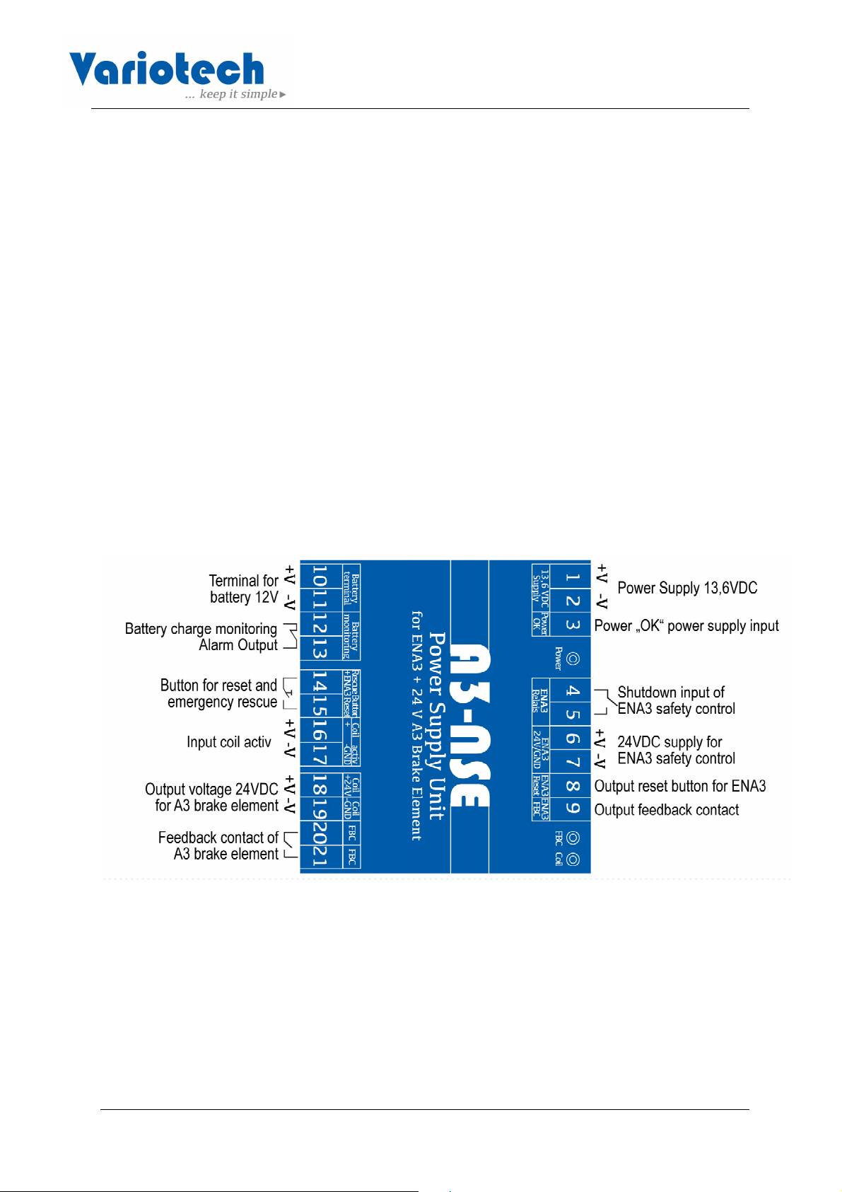
Connections and terminals description:
Terminal 1 (+V), 2 (-V): Connection of a suitable external power supply with an input voltage of 230V
and an adjustable output voltage from 12VDC + / -20% min 3A. The output voltage must be set to 13.6
volts before commissioning (suitable power supply would be Meanwell MDR-40-12).
Terminal 3: Connection for the potential-free output contact (relay) "power ok" of the power supply.
Terminals 4, 5: Connection for a safety relay contact of the A3 safety control, which opens in case of
an A3 error. This input is used to turn off the supply voltage of the A3 brake element if an A3 error
occurs.
Terminals 6(-V), 7 (+V): Connection of the power supply 24V DC 0,3A of the A3 safety control.
Terminal 8: Reset button output for connection to the reset button input of A3 safety control.
Terminal 9: Output "feedback of the A3 brake element" to connect to the A3-safety control.
This output indicates the function of the A3 brake element. The switch position is dependent on the
switch on the A3 brake element.
Terminals 10 (+V), 11 (-V): Connection of an external 12V battery. The battery can have a capacity
ranging from 1.2 Ah to 7.5 Ah
Terminals 12, 13: Output (potential-free relay contact, normally closed) for reporting a battery failure.
Terminals 14, 15: Connection for an external switch for the initiation of the emergency rescue and as
well as for the reset of the A3 safety control.
Terminals 16, 17: Connection for an external LED which indicates if the coil is active.
Terminals 18 (-V), 19 (+V): Output voltage 24VDC for the A3 brake element.
Terminals 20, 21: Connection for the switch (feedback control) on the A3 brake element.
Signal transmitter:
The power supply NSE has a built-in electric signal transmitter (beeper / buzzer) which generates an
acoustic signal to indicate an error and easier fault location in case of error.