Sole Diesel SVT 10 User manual

Rev. 1

2
Operator’s Manual SVT Panels
Revision 1. 07/2017

TABLE OF CONTENTS
3
Operator’s Manual SVT Panels
Revision 1. 07/2017
TABLE OF CONTENTS
TABLE OF CONTENTS..........................................................................................................................................3
1. General information .....................................................................................................................................4
1.1. Introduction to SVT ...............................................................................................................................4
2. Panel parts......................................................................................................................................................5
3. Settings ............................................................................................................................................................6
3.1. Tachometer calibration and replacing the light bulb....................................................................6
4. Service Assistance.........................................................................................................................................6
GENERAL INFORMATION
4
Operator’s Manual SVT Panels
Revision 1. 07/2017
1. General information
In accordance with our technological quality policy, SOLÉ DIESEL is constantly applying
upgrades on existing products in order to improve customer satisfaction and engine performance. Our
new SVT 10/20/30/40 are a product of this development.
Moreover, we only recommend using our Assistance Service for any servicing or intervention needs on
the item and using original spare parts. Otherwise, SOLÉ S.A. WILL BE RELEASED FROM ANY WARRANTY
AND TECHNICAL SERVICE OBLIGATIONS
1.1. Introduction to SVT
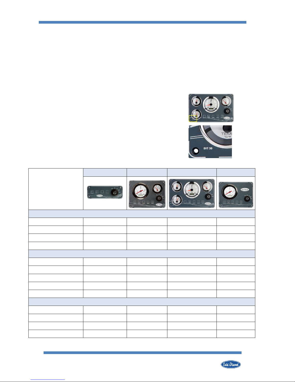
The SVT range consists of a control and protection panel set
used with propulsion engines. All units are designed for easy
operation by both the installer and the end customer, with different
degrees of performance, depending on the model. All panels are
identified according to their model in the bottom right section
(model SVT 10 is identified on the right).
PANEL
SVT 10
SVT 20
SVT 30
SVT 40
ELECTRONIC BOARD
Pre-heating pilot light
Battery alarm
High temperature alarm
Low oil pressure alarm
FIVE POSITIONS KEY SWITCH
Engine stop
Turn off electronic board
Turn on electronic board
Engine pre-heating
Engine start-up
FIVE POSITIONS KEY SWITCH
Tachometer / Hourmeter
-
Coolant temperature gauge
-
-
Oil pressure gauge
-
-
-
Voltmeter
-
-
-

PANEL PARTS
5
Operator’s Manual SVT Panels
Revision 1. 07/2017
2. Panel parts
PRE-HEATING
The LED light turns on when the pre-heating spark plugs receive power. It turns
off after a few seconds to indicate that the engine is ready for start-up.
NOTE: The only purpose of this LED is to inform the user, it does not act on the
engine. The pre-heating spark plugs keep working even if the LED light is not on.
BATTERY CHARGING FAULT
The LED and the buzzer are activated when the alternator is not charging the
battery.
NOTE: When the engine is off, the alternator is usually not charging and this
alarm is on.
HIGH COOLANT TEMPERATURE
The LED and the buzzer turn on when the coolant temperature is too high.
NOTE: This alarm should never appear during normal engine operation.
LOW OIL PRESSURE
El led y el zumbador se encienden cuando la presión de aceite es demasiado
baja.
NOTA: Cuando el motor está apagado es normal que la presión del aceite sea
baja y esta alarma esté funcionando.
HIGH SEAWATER TEMPERATURE
This panel part is prepared to install a LED that turns on when the seawater
temperature at the exhaust outlet is more than 70ºC. In addition, in case of
alarm, the buzzer will emit a sound. It is necessary to install the kit alarm
temperature exhaust ref. 60900280.
FIVE POSITION KEY SWITCH
The contact key switch is directly connected to the battery (PIN 30) and
depending on its position (STOP, OFF, ON, PRE-HEATING, START), the key supplies
certain pins/connectors where the different electronic devices are connected.
TACHOMETER AND HOURMETER
The tachometer displays the revolutions of the engine and is adjusted for each
engine model. If the panel is to be used for an engine other than Solé Diesel
models, the tachometer should be adjusted (see Section 2.2.4).
The screen located at the bottom of the clock is the work hours counter.
The hourglass blinks when its counting the work hours; if it does not blink, it
is not counting.
COOLANT TEMPERATURE GAUGE
The thermometer indicates the coolant temperature.
The pressure meter indicates the pressure of the lubrication
circuit.
VOLTMETER
The voltmeter indicates the voltage of the engine electrical installation,
generated by the alternator.
NOTE: During the start-up stage, when the key switch is at the ON and
PREHEATING POSITION, the meter displays the battery voltage, as the
alternator is not yet working.
SETTINGS
6
Operator’s Manual SVT Panels
Revision 1. 07/2017
3. Settings
3.1. Tachometer calibration and replacing the light bulb
The tachometers supplied with the panel are calibrated in the factory. The user must only
calibrate tachometers purchased as spare parts.
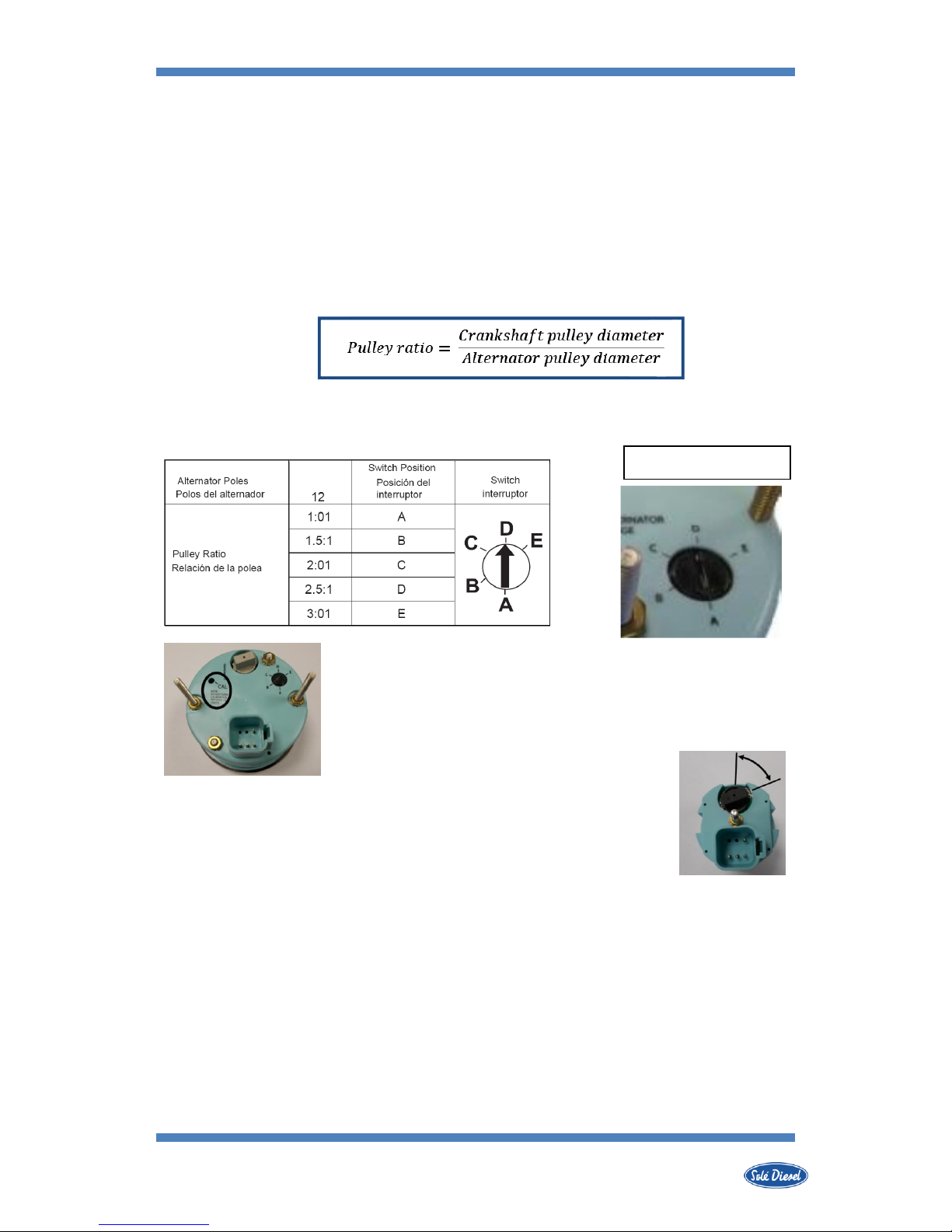
The tachometer can be calibrated with the switch at the rear. To know its position, the
pulley ratio must be calculated.
After calculating the pulley ratio, refer to the table (approximate value, if required) and
rotate the tachometer switch.
If the pulley ratio is not exactly the same as in the table, the calibration
must be completed with the Calibrator (CAL). Introduce a small flat
screwdriver into the calibrator (CAL) at the rear of the meter. Carefully
calibrate the mechanism moving the meter needle forwards or
backwards until it corresponds to the engine speed.
Unscrew the cap of the light bulb (rear of the meters) and change the light
bulb.
4. Service Assistance
For an updated list of our distribution network, visit Dealers section in our web page
www.solediesel.com. Or request this information by contacting Solé Diesel at:
Phone: +34 93 775 14 00
Tachometer Switch
Interruptor del Tacómetro


Rev. 1
This manual suits for next models
3
Table of contents
Other Sole Diesel Control Panel manuals


