Sole Digital Liftlog XL User manual

Liftlog™XL
Advanced Crane Data Logger
Model LL300, Version 2.0
Installation and User Manual
V1.8: 07/10/2013
© CASWA Pty Ltd –2013

© CASWA Pty Ltd –2013 2 | Page
CONTENTS
1OVERVIEW .......................................................................................................................... 4
1.1 Liftlog™XL Versions ............................................................................................................................... 4
2SPECIFICATIONS.................................................................................................................... 5
2.1 Operational Specifications .................................................................................................................... 5
2.2 Physical Specifications........................................................................................................................... 5
2.3 Electrical Specifications......................................................................................................................... 6
2.4 Communication Specifications.............................................................................................................. 6
3INSTALLATION DETAILS ......................................................................................................... 7
3.1 Prior to Installation ............................................................................................................................... 7
3.2 Inserting/Changing Your SIM Card ........................................................................................................ 7
3.3 Wiring Details........................................................................................................................................ 7
3.3.1 Terminals .............................................................................................................................. 8
3.3.2 Connecting the Power Supply............................................................................................. 11
3.3.3 Connecting Motion Inputs ............................................................................................... 13
3.3.4 Connecting Limit Inputs ................................................................................................... 14
3.3.5 Connecting Load Sensor Inputs ....................................................................................... 15
3.3.6 Connecting the Fault Output .............................................................................................. 17
4COMMISSIONING DETAILS .................................................................................................. 18
4.1 Installing and Launching the FSU Application ..................................................................................... 18
4.1.1 FSU Program Installation .................................................................................................... 18
4.1.2 Installing the FSU application ............................................................................................. 18
4.1.3 Launching the application................................................................................................... 18
4.2 Connecting to the Device .................................................................................................................... 19
4.3 Checking for Firmware ........................................................................................................................ 19
4.4 Checking the Date/Time...................................................................................................................... 20
4.5 General Tab ......................................................................................................................................... 21
4.5.1 Setting Equipment Name .................................................................................................... 21
4.5.2 Upload Data to the Computer ............................................................................................ 21
4.6 Main and Aux Hoist Configuration ...................................................................................................... 21
4.6.1 Input Selection .................................................................................................................... 22
4.6.2 Using/Removing a HoistNet Input ...................................................................................... 22
4.6.3 Using the LiftlogXL with a ControlPro ................................................................................. 23
4.6.4 Checking the Gain ............................................................................................................... 24
4.6.5 Calibrating the Logger......................................................................................................... 24

© CASWA Pty Ltd –2013 3 | Page
4.6.6 Resetting the Calibration .................................................................................................... 25
4.7 Comms Tab.......................................................................................................................................... 25
4.7.1 3G configuration ................................................................................................................. 25
4.7.2 Link Status........................................................................................................................... 25
4.8 Inputs and Limits................................................................................................................................. 26
4.8.1 Using XL devices with a HVDC IO Expander ........................................................................ 26
4.8.2 Tuning Sensitivity and Noise Immunity............................................................................... 27
4.9 Overloads ............................................................................................................................................ 27
4.9.1 Main, Aux and Combined.................................................................................................... 27
4.9.2 Overload Sensitivity ............................................................................................................ 27
4.9.3 Lockout ............................................................................................................................... 27
4.10 SD Card Management ......................................................................................................................... 28
4.10.1 Test SD Card........................................................................................................................ 28
4.10.2 Reformat SD Card ............................................................................................................... 29
4.11 Running CheckIt Diagnostics ............................................................................................................... 29
4.12 Recording a Service ............................................................................................................................. 30
5ROUTINE MAINTENANCE .................................................................................................... 31
6OPERATING LIFTLOG™XL..................................................................................................... 32
6.1 Operating Status ................................................................................................................................. 32
6.2 Accessing Your Data ............................................................................................................................ 32
6.2.1 Downloading Data .............................................................................................................. 33
8TROUBLESHOOTING............................................................................................................ 34
Appendix A: COMMUNICATION PROTOCOL ......................................................................... 35
Appendix B: COMMUNICATION OPTIONS ............................................................................ 37
B.1 How Much Data?................................................................................................................................. 37
B.2 Australian Carriers............................................................................................................................... 37
Appendix C: FSU SYSTEM REQUIREMENTS ........................................................................... 38
Appendix D: DATA FILE FORMAT.......................................................................................... 39

© CASWA Pty Ltd –2013 4 | Page
1OVERVIEW
Liftlog™XL is an advanced remaining life and load limiting data-logger for cranes. It can
simultaneously monitor two hoists and in addition to logging vertical lifting motions, also supervises
long and cross travel. Overloads and dangerous usage will trigger immediate email or SMS alerts.
Data is automatically downloaded in real time using GSM/3G/GPRS or WIFI connectivity.
Liftlog™XL is particularly well suited to users seeking an integrated enterprise solution for crane
monitoring and management, high risk applications requiring increased oversight of crane operation
and dual hoist or process cranes.
1.1 Liftlog™XL Versions
Liftlog™XL V2 devices are marked with a serial number that begins with a 2 (e.g. 2-001, 2-974).
If you have a Liftlog™XL with a two or 3 digit serial number that is smaller than 200 (e.g. 72, 196),
you have a V1 device and you should refer to the Liftlog™XL V1 Installation and User Manual.

© CASWA Pty Ltd –2013 5 | Page
2SPECIFICATIONS
2.1 Operational Specifications
Parameter
Description
Min
Typ
Max
Units
Lcount
Maximum number of logged events
10,000,000
Flog
Frequency of logged events
4
Hz
Tlog
Duration of a logged event
1
30000
Sec
2.2 Physical Specifications
Overall length (mm):
157
Overall width (mm):
86
Overall height (mm):
58
Weight (kg):
0.3
Mounting:
Screwed or 30mm DIN rail
Electrical connections:
56 x screwed terminals
Detailed dimensions of the Liftlog™XL case are provided in the following diagram (where all
dimensions are shown in mm):
Figure 1: Case Dimensions

© CASWA Pty Ltd –2013 6 | Page
2.3 Electrical Specifications
Parameter
Description
Min
Typ
Max
Units
Vin
Supply voltage
24
12
250
48
VAC
VDC
Iin
Supply current
40
100
mA
Vlimit
Overload relay voltage
60
VAC
Ilimit
Overload relay current
0.5
2
V
Vlimit
Limit Switch input voltage
60
VAC
Lsense
mv load sensor sensitivity
0.5
10
mV/V
Rin
Input impedance of 0-10V input
1500
Ohms
I24
24V output current
100
mA
Operating temperature
-40
85Note 2
°C
Notes:
1. Power supply –ve and GND pins are at chassis GND (0V) potential
2. Extended operation at maximum temperature will reduce the life the device.
2.4 Communication Specifications
Communications between the device and a host is usually via a Bluetooth radio link. The Bluetooth
device name will be set to the Crane ID, the PIN is 0000.
For more details on the communication protocol used to communicate with the Liftlog™XL, see
Appendix A.
© CASWA Pty Ltd –2013 7 | Page
3INSTALLATION DETAILS
3.1 Prior to Installation
Before installing your Liftlog™XL device visually inspect the unit and check that:
(a) the case is not damaged and fits together securely;
(b) terminals are secure;
(c) terminal numbering is as per section 3.3.1 (i.e. stickers have been correctly placed).
If you have chosen to install your own SIM card, then this should be inserted now. Details are
provided in the following section.
The antenna can also be screwed into the front terminal now.
3.2 Inserting/Changing Your SIM Card
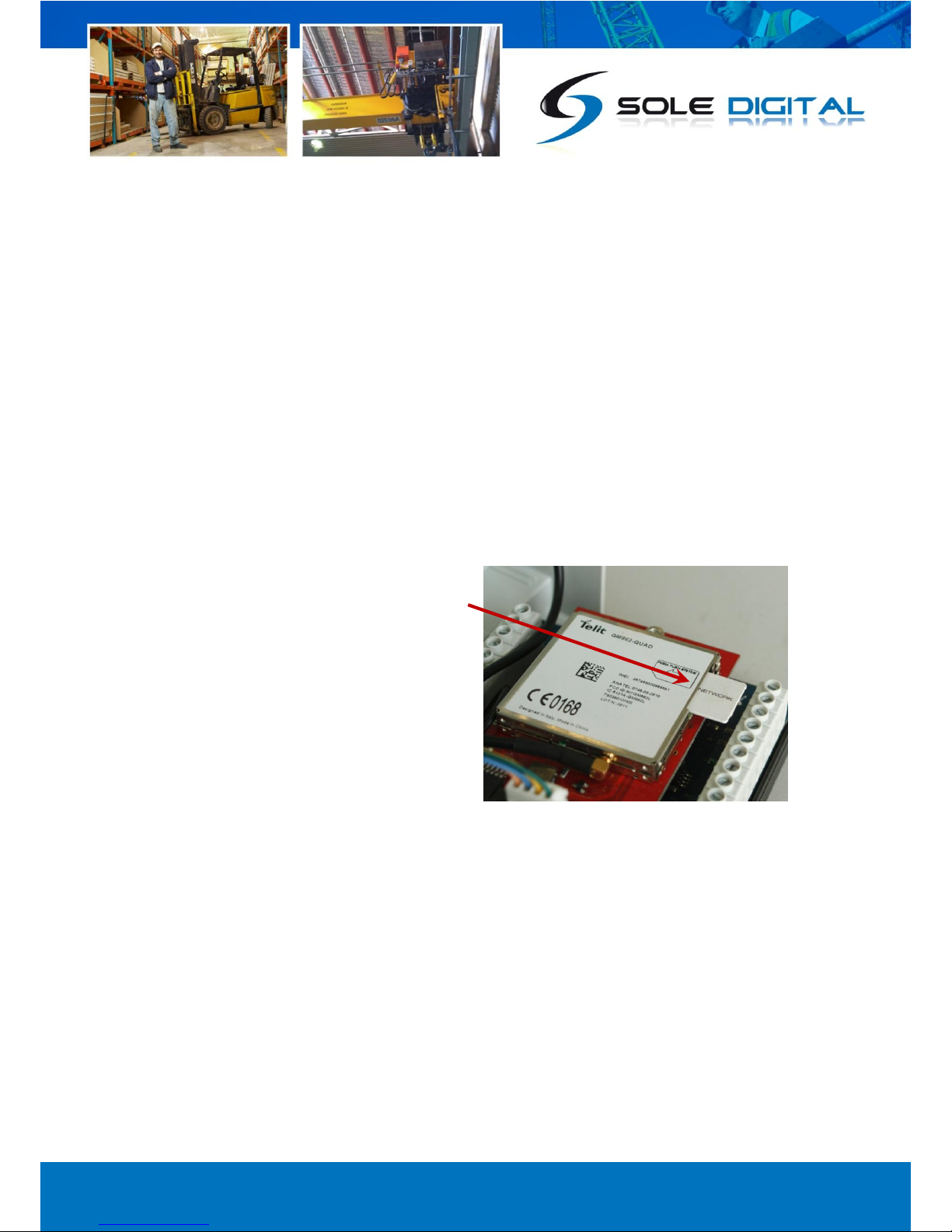
Remove the lid from the unit by releasing the clips at each end to reveal the internal circuit boards.
Locate the SIM card socket on the upper circuit
board and insert a data SIM card into the socket
shown. Push the card in fully so that it engages.
For details on what SIM cards are compatible
with Liftlog™XL see Appendix B: Communication
Options.
Replace the cover.
3.3 Wiring Details
For the Liftlog™XL to operate the following must be connected as a minimum:
a. Power supply; plus
b. 1 or more inputs (motion, limit or load cell).
The following additional types or inputs are optional:
Up to 15 motion inputs; and/or
Up to 9 limit inputs; and/or
Up to 2 load cells (of any type); and/or
2 Fault outputs.

© CASWA Pty Ltd –2013 8 | Page
3.3.1 Terminals
Please note that the terminals of Liftlog™XL have changed slightly for different versions of the
product. Label descriptions have also been altered slightly.
Sticker orientations showing terminals, for Liftlog™XL devices with serial numbers that start with a
‘2-’ (i.e. numbers greater than 199) are as follows:
Figure 2: Version 2 Sticker Orientations
1 2 3 4 5 6 7 8 9 10 11 12 13 14 15 16 17 18 19 20 21 22 23 24 25 26
27 28 29 30 31 32 33 34 35 36 37 38 39 40 41 42 43 44 45 46 47 48 49 50 51 52

© CASWA Pty Ltd –2013 9 | Page
The following table describes each terminal on Liftlog™XL units that have serial numbers starting
with a ‘2-’ (i.e. greater than 199).
Terminal
Number
Description
Label
1.
Negative reference for mV, mA and V sensors
(black wire on RC-3 or RC-5 rope clamps)
GND
2.
-ve sense input for MAIN Hook strain gauge (mV) load cell/pin
(white wire on RC-3 or RC-5 rope clamps)
-
MAIN
3.
+ve sense input for MAIN Hook strain gauge (mV) load cell/pin
(green wire on RC-3 or RC-5 rope clamps)
+
4.
Excitation voltage (3.3V) for MAIN hook strain gauge (mv) load cell/pin (red
wire on RC-3 or RC-5 rope clamps)
XCite
5.
Return connection for MAIN Hook 4-20mA strain gauge (mA) load cell/pin, or
output from load display
4-20mA
6.
0-10V input for MAIN hook from loadcell/pin amplifier or Konecranes Control-
Pro
0-10V
7.
Connection for MAIN hook to terminal Q, F1, or F2, on an ABUS LIS
Q-Link +
8.
Connection for MAIN hook to Ground on an ABUS LIS
Q-Link -
9.
Drive voltage for 4-20mA sensor
24V
10.
Auxiliary inputs 1-3 can be used for any function (e.g. magnets, twist locks
etc.) All are AC inputs across the range 48-240VAC
Aux1
11.
Aux2
12.
Aux3
13.
AC input indicating East-West motion is fast
E-W Fast
14.
AC input indicating West Travel
West
15.
AC input indicating East Travel
East
16.
AC input indicating North-South travel is fast
N-S Fast
17.
AC input indicating South Travel
South
18.
AC input indicating North Travel
North
19.
AC input indicating AUX Hook up/down is fast
Fast
AUX
20.
AC input indicating AUX hook lowering
Down
21.
AC input indicating AUX hook raising
Up
22.
AC input indicating MAIN Hook up/down is fast
Fast
MAIN
23.
AC input indicating MAIN hook lowering
Down
24.
AC input indicating MAIN hook raising
Up
25.
Neutral (0VAC) power connection
0V AC
26.
Live (48-240VAC) power connection
24-240V AC
27.
Shield/0V
GND

© CASWA Pty Ltd –2013 10 | Page
28.
0-10V input for AUX hook from loadcell/pin amplifier or Konecranes Control-
pro
0-10V
AUX
29.
Return connection for AUX hook 4-20mA strain gauge (mA) load cell/pin, or
output from load display
4-20mA
30.
Excitation voltage (3.3V) for AUX hook strain gauge (mv) load cell/pin (red
wire on RC-3 or RC-5 rope clamps)
XCite
31.
+ve sense input for AUX Hook strain gauge (mV) load cell/pin (green wire on
RC-3 or RC-5 rope clamps)
+
32.
-ve sense input for AUX Hook strain gauge (mV) load cell/pin (white wire on
RC-3 or RC-5 rope clamps)
-
33.
GND negative reference for mV, mA, and V sensors (black wire on RC-3 or RC-
5 rope clamps)
GND
34.
Connection for AUX hook to gnd on an ABUS LIS
- Q-Link
35.
Connection for AUX hook to terminal Q, F1, or F2, on an ABUS LIS.
+Q-Link
36.
Drive voltage for 4-20mA sensor
24V
37.
Opto-isolated limit input, can be used for any limit function
AUX2
38.
AUX2
39.
Opto-isolated limit input, can be used for any limit function
AUX1
40.
AUX1
41.
Opto-isolated side pull input for AUX Hook. Connect across up inputs on
SideWise signal processor.
SidePull
AUX
Limits
42.
SidePull
43.
Opto-isolated ultimate limit input for AUX Hook.
Top
44.
Top
45.
Opto-isolated side pull input for MAIN Hook. Connect across up inputs on
SideWise signal processor.
SidePull
MAIN
Limits
46.
SidePull
47.
Opto-isolated ultimate limit input for MAIN Hook.
Top
48.
Top
49.
AUX hook load limit output 48-240VAC 4A NO/NC
Fault2
50.
Fault2
51.
MAIN hook load limit output 48-240VAC 4A NO/NC
Fault1
52.
Fault1
© CASWA Pty Ltd –2013 11 | Page
3.3.2 Connecting the Power Supply
Series 2 Liftlog™XL is designed to operate from 24-240VAC grounded neutral. (Note: Series 1 units
could only operate from 48-240VAC.)
It can also operate from 12-48VDC, however this is not preferred as load limits cannot be used in this
configuration. For more information on driving the Liftlog™XL from a DC power source, contact
Liftlog™XL requires constant power so that it can maintain a connection to the 3G/GPRS network.
Do not connect the unit after the K1 or E-Stop relay. Doing so will cause erratic behaviour and
premature failure of the Liftlog™XL electronics.
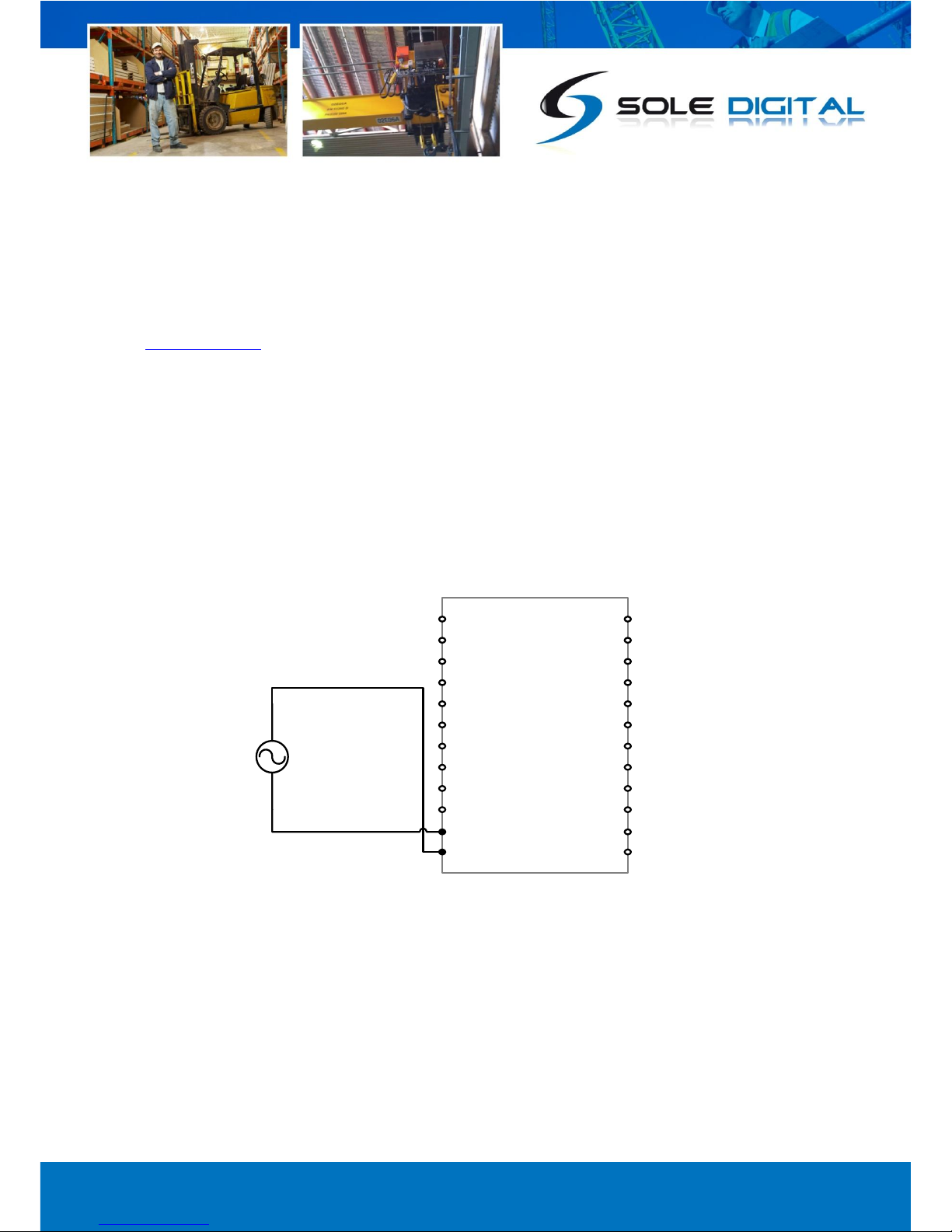
3.3.2.1 Using an AC Power Source
To connect an AC source from 24-240VAC wire active and neutral as follows.
LiftlogXL
25: 0VAC #
26: 24-240VAC
24-240VAC (Active)
24-240VAC
Power Supply
0V (Neutral)
Notes:
# All pins marked as ‘GND’ are connected
internally to pin 25, 0VAC.
Figure 3: Connecting an AC Power Source

© CASWA Pty Ltd –2013 12 | Page
3.3.2.2 Using a DC Power Source
To connect a DC source from 12-24VDC wire active and neutral as follows.
It is important to remember that when powering the Liftlog™XL from a DC source, that it may not be
possible to use the load limiting functions of the Liftlog™XL as the outputs only switch AC.
LiftlogXL
25,27: 0VAC #
9,36: 24V
12-24VDC
0V (Neutral)
Notes:
# All pins marked as ‘GND’ are connected
internally to pin 25, 0VAC.
12-24V DC
Power Supply
Figure 4: Connecting a DC Power Source
© CASWA Pty Ltd –2013 13 | Page
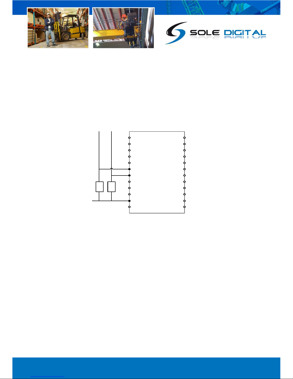
3.3.3 Connecting Motion Inputs
Motion input pins (Aux1, Aux2, Aux3, E-W Fast, West, East, N-S Fast, South and North) must be
connected to GND or 0VAC (pins 1, 25, 27, 33) by a set of voltage independent contacts. Where
spare or auxiliary contacts are not available on the MAIN contactors, small relays must be employed.
For example, the DOWN and UP inputs on the Auxiliary hoist would be connected as follows:
LiftlogXL
25, 1, 27, 33: GND
21: Aux UP
20: Aux DOWN
D U
To existing control
circuitry
0V
Figure 5: Connecting Motion Inputs

© CASWA Pty Ltd –2013 14 | Page
3.3.4 Connecting Limit Inputs
There are two input pins for each limit input (e.g. Pins 45 and 46 for the Main hoist SidePull limit).
Each input pair should be connected across the limit switch, or chain of limit switches, to be
monitored. All limit inputs are voltage independent and typically configured to be normally closed
(i.e. any voltage across these terminals keep the limit from activating).
For example, the Main Hoist SidePull limit would be connected as follows:
LiftlogXL
45: MAIN SidePull
MAIN hoist
SidePull Sensor
46: MAIN SidePull
Figure 6: Connecting Limit Inputs

© CASWA Pty Ltd –2013 15 | Page
3.3.5 Connecting Load Sensor Inputs
The Liftlog™XL supports two load sensor inputs (marked MAIN and AUX) of various types:
a) Strain gauge input (e.g. CASWA rope clamp load cell);
b) 4-20mA input;
c) 0-10V input;
d) ABUS LIS Q, F1 or F2 inputs.
The load sensor for the MAIN hoist is connected to pins 1-7, the load sensor for the auxiliary hoist
connects to pins 28-34.
It can also accept wireless inputs for both the MAIN and AUX hooks via HoistNet.
3.3.5.1 Strain gauge input
When using a strain gauge load cell to measure the load on either the MAIN or the AUX hooks, all
four wires from the strain gauge need to be connected. For the MAIN hook, these should be
connected as follows:
The AUX hook can be connected in the same way using pins 30 to 33.
LiftlogXL
3: +
2: -
1: GND
4: +XCite
Green
Black
Red
White
Notes:
Colour codes are for CASWA supplied
rope clamp load cells.
Figure 7: Connecting a Strain Gauge Input

© CASWA Pty Ltd –2013 16 | Page
3.3.5.2 4-20mA load sensor input
When using a 4-20mA signal to monitor the load, connect the load sensor between pins 5 and 9 for
the MAIN hoist and pins 29 and 36 for the AUX hoist.
3.3.5.3 0-10V Load Sensor
When using a 0-10V signal to monitor the load (e.g. from a Konecranes ControlPro), connect the load
sensor between pins 1 (or any other pin marked GND) and 6 for the MAIN hoist and pins 33 and 28
for the AUX hoist.
4-20mA
Load Sensor
on MAIN hook
LiftlogXL
5: 4-20mA
9: 24V
0-10V Signal
for MAIN hook
(External device, Amp etc)
LiftlogXL
1: GND
6: 0-10V
Figure 8: Connecting a 4-20mA Input
Figure 9: Connecting a 0-10V Load Input
© CASWA Pty Ltd –2013 17 | Page
3.3.5.4 ABUS LIS Q or Frequency Input
Liftlog™XL will also accept a load signal from either the Q, F1 or F2 terminals of an ABUS LIS. This has
the advantage of not requiring a separate calibration of the load signal.
In this scenario the load signal from the ABUS LIS (marked as Q, F1 or F2) is connected into the ‘Q-
Link +’ terminal on the LiflogXL (pin marked 7 or 35 for the MAIN and AUX hoists respectively), whilst
the ABUS LIS ground is connected into the ‘Q-Link-’ terminal (pin marked 8 or 34 for the MAIN and
AUX hoists respectively).
Connecting a signal for the MAIN hoist is depicted as follows:
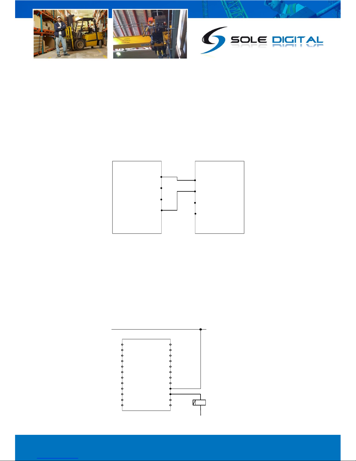
3.3.6 Connecting the Fault Output
The two fault outputs (marked Fault1 and Fault2) are normally closed relays which open when an
overload is detected. They are typically wired in series with the UP contactor coil. On a dual hoist
crane an interposing relay may be required if both hoists are to be inhibited.
For example, connecting up the Fault2 output:
LiftlogXL
8: Q-Link -
7: Q-Link +
ABUS LIS
GND
Q, F1, F2
Figure 10: Connecting a Q-Link Input
LiftlogXL
49: Fault2
50: Fault2
Kx UP
Figure 11: Connecting the Fault Output

© CASWA Pty Ltd –2013 18 | Page
4COMMISSIONING DETAILS
Liftlog™XL is designed to be commissioned using a laptop computer. You will need a CASWA LINK-2
Bluetooth Modem and the Field Service Utility (FSU) software application loaded on a laptop.
4.1 Installing and Launching the FSU Application
4.1.1 FSU Program Installation
Ensure that your computer is switched on, connected to the internet and that the minimum required
software versions are installed (see Appendix B: for minimum system requirements). Ensure that
the LINK-2 modem is installed and that the drivers have loaded.
4.1.2 Installing the FSU application
The latest LINK-2 FSU software (Link-2_FSU) can be downloaded from
http://www.soledigital.com.au/Link2.html.
You should check this location regularly for updates.
4.1.3 Launching the application
Double click on the FSU program icon: .

© CASWA Pty Ltd –2013 19 | Page
4.2 Connecting to the Device
The FSU will scan for Bluetooth enabled devices. This process takes approximately 10 seconds;
when complete a list of all CASWA devices within range will be displayed.
If a particular Liftlog™XL unit is not found, ensure it is powered up and press <Look again> to repeat
the search.
Version 2 Liftlog™XL devices are differentiated from version 1 devices by a 'II' superimposed over
the device icons.
NB: The Bluetooth link between the Laptop using a Link-2 and a Liftlog™XL has a range of
approximately 200m.
Double-Click on the Liftlog™XL you wish to configure.
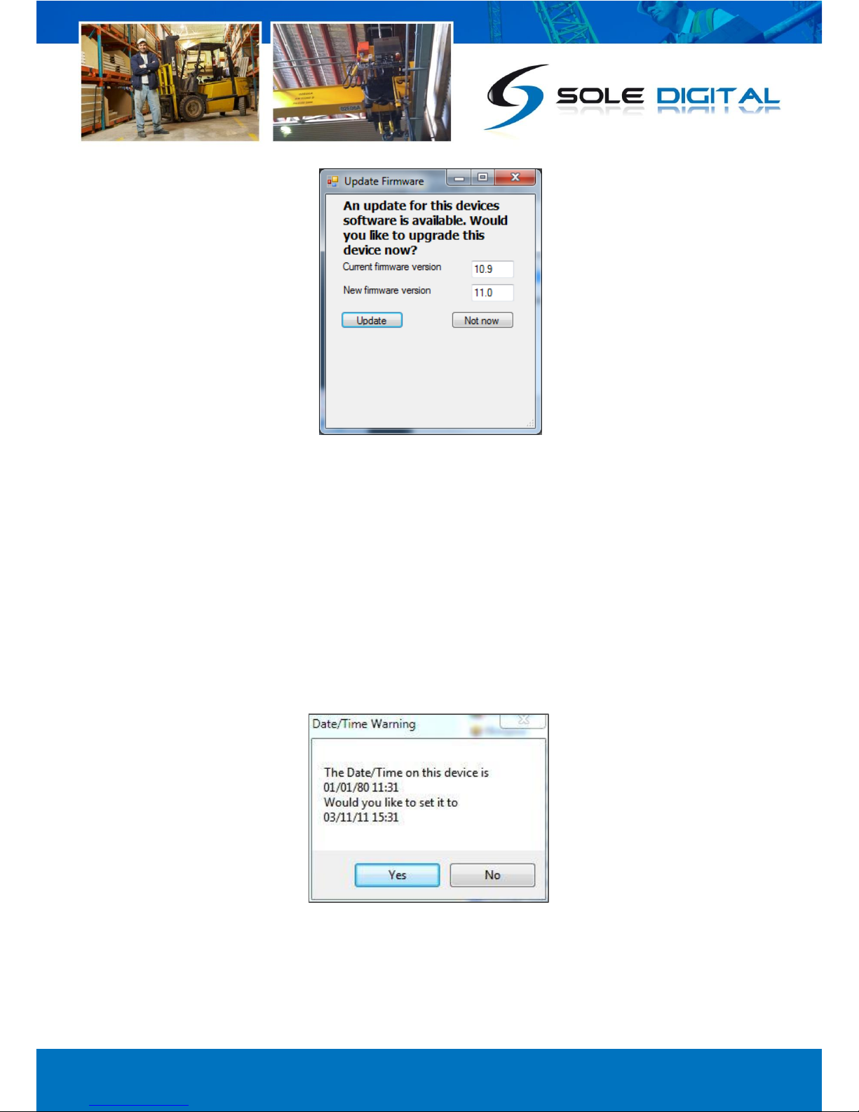
4.3 Checking for Firmware
After you have selected your desired Liftlog™XL, a connection will be made and the software will
check if the device has the current firmware. If a new firmware version is available the following
window will pop up:
© CASWA Pty Ltd –2013 20 | Page
Press <Update> to update the Liftlog™XL to the latest available firmware version (recommended).
The new firmware will be installed on the device. DO NOT switch off the computer or remove the
LINK2 modem until this is complete –doing so may leave the Liftlog™XL in an unrecoverable state.
Alternatively, press <Not now> to update firmware at a later time.
NB: If you did not see this window, then your device already has the most current firmware.
4.4 Checking the Date/Time
After checking for firmware the FSU application verifies whether the Liftlog™XL has the same
date/time as your computer.
If the times are not the same, the following pop up window will display on the screen:
Press <Yes> to update the devices date/time or press <No> to leave the date/time on the device as it
is.
NB: If you did not see this window, then your device has the same date/time as your computer.
This manual suits for next models
1
Table of contents
Popular Other manuals by other brands

sammi
sammi SmarTerminal SmartNL-RF2000 user guide

EcoSeb
EcoSeb DD1EA SIMPLE manual

Eaton
Eaton digtrip 510 with zone Interlock Installation, operation and maintenance

SciCan
SciCan Hydrim C61wd G4 Operator's manual

fish mate
fish mate 1200 instructions

Stratasys
Stratasys CLEANSTATION CSIIP Site preparation guide


