Solectek 70MOB1 User manual

SKYWAY-MOBILE SERIES
Base Transceiver Station
User’s Guide
July 2008
Rev 1

Note: Any changes or modifications not expressly approved by the party responsible for
compliance could void the user’s authority to operate the equipment.
This device complies with Part 15 of the FCC Rules. Operation is subject to the following
(1) This device may not cause harmful interference, and
(2) This device must accept any interference received, including interference that may
cause undesired operation.
NOTE:This equipment has been tested and found to comply with the limits for a Class
A digital device, pursuant to Part 15 of the FCC Rules. These limits are designed to
provide reasonable protection against harmful interference when the equipment is
operated in a commercial environment. This equipment generates, uses, and can radiate
radio frequency energy and, if not installed and used in accordance with the instruction
manual, may cause harmful interference to radio communications. Operation of this
equipment in a residential area is likely to cause harmful interference in which case the
user will be required to correct the interference at his/her own expense.

1. Introduction
Congratulations on your purchase of a SkyWay-Mobile BTS system. This user’s guide
contains basic description of the system, basic installation and configuration steps to act as
a basic guideline for the end user. This guide is not to act as a step-by-step guide for self-
installation by end users.
This product requires a full professional installation services by Solectek’s field engineering
staff or authorized reseller officially certified by Solectek. The installation services will
include the following work:
Site survey and RF planning.
Drive test, mapping of the coverage area.
Physical mounting of the outdoor components on tower or rooftop
Antenna alignment
Configuration, calibration and troubleshooting
Commission of the service
Product Features
The SkyWay-Mobile BTS unit has the following features
Throughput – up to 15 Mbps in a 5 MHz channel BW.
Chanel BW – 1, 2, 3, 4, or 5 MHz, user configurable
Support for more than 300 subscribers
Support for 150 simultaneous phone calls
N=1 Frequency reuse
Voice service support – proprietary mode or VoIP

2. Installation
Installation Cabinet
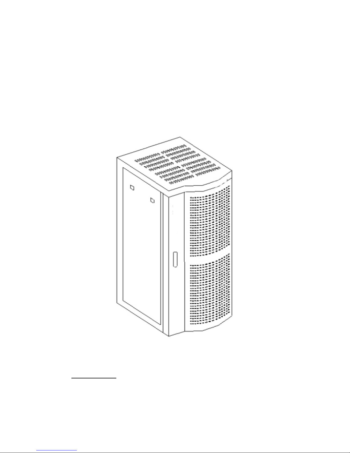
The SkyWay-Mobile BTS is typically installed in a standard 19 inch cabinet. The outer
dimensions are:
Height x Width x Depth – 1550 mm x 600 mm x 722 mm
The following is a diagram of the cabinet, as an example.
Fig 2-1: SkyWay-Mobile BTS cabinet
2.2 Position and Installation of Cabinet
Layout of Cabinet

It is recommended to position the BTS cabinet as shown in Figure 2-2 in accordance
with the following guidelines.
The spacing between the rear side of the cabinet and the wall should be at least
600mm.
In the front side of the cabinet, at least 600mm spacing should be reserved as a work
area.
Fig 2-2: Layout of the network facility and location of BTS cabinet
Place the cabinets based on the engineering design requirements and accurately mark
out the positions of the supports on the floor. Install the accessories for cabinet
installation, as shown in Figure 2-3. Drill vertical holes with the appropriate punch drill
and drill bit, and then install M12 expansion bolts.
Figure 2-3: Installation of cabinet accessories
Do not over tighten the expansion bolts so that the installation accessories can be easily
moved if necessary. Install the cabinet in the preset position, and then rotate the

accessories to move the U-shape opening on the corresponding round steel bar of the
cabinet support, as show in Figure 2-5.
Figure 2-4 Bottom of the cabinet
Position the cabinet, make it sit flat by using a level and then tighten the expansion bolts.
Check the insulation impedance with a meg-ohmmeter between the cabinet and the floor
and make sure that the value is greater than 5MΩ.
2.3 BTS Installation
The overall structure of the BTS is shown in Figure 2-5.
Open the cabinet door, adjust the partition positions, push the BTS into the sub-rack.
Record the model and Factory No. of the BTS and cable loss data for future references.
Keep this set of information at an easily accessible location.
Make sure that any empty slot in the BTS enclosure is filled in with a cover panel.

Figure 2-6: Rack-mount BTS Enclosure
2.4 Connection of Ethernet Cable
The following diagram (Fig 2-7) shows the connections between the BTS and a network
switch. The data interface on the BTS is Ethernet with standard RJ-45 connector, as
shown below in Figure 2-7.
Figure 2-7 RJ-45 Ethernet Connector
Fabricate the Ethernet cable using the RJ-45 connectors shown in Fig 2-7. Connect one
end to the Ethernet port located on the bottom left side of the BTS front panel as shown
in Fig 2-8 and the other to a network switch or other transmission equipment.

Fig 2-8: Front panel of the BTS with the Ethernet port
2.5 Connect Power Cable
The BTS uses a DC+24V power supply. A +24V power source may be locally available
as part of telco closet facility. Solectek supplies either of the following power supply
options in case that the user needs to use a separate stand-alone power supply.
220/120 V AC to +24V DC power supply unit.
-48V DC to 24V DC power supply unit (in case -48V DC is available on site).
A stand-along power supply must be securely installed in the cabinet. An example of a
typical power supply is shown in Figure 2-9.

Fig 2-9: An example of a stand alone power supply to be installed in the cabinet
In case of an AC installation, first use a standard electrical cord to bring 120/220V AC to
the power supply’s AC input, connect the equipment’s DC output to the cabinet’s circuit
breaker and then the grounding to the cabinet’s pooling current bar.
WARNING: AC/DC equipment installation and use must strictly comply with the AC/DC
equipment instruction requirements, and reliable grounding must be finished through
grounding cable
Figure 2-10: BTS rear panel with BTS power cable connections shown.

Use flame retardant cables as base station power cables, press them out through Ф6
copper lug, and screw down on the base station power wire posts, as shown in Figure 2-
10.
Connect one end of the DC+24V power cable to the air switch at the cabinet’s bottom,
the red is connected to the positive pole, and the blue is connected to the negative pole.
Connect the other end to DC power cabinet’s output terminal correspondingly, the red is
connected to the positive pole (the working ground), and the blue is connected to the
negative pole. One end of the greenish yellow is connected to the pooling current bar of
the base station cabinet, and the other end is connected to the protection grounding bus
bar in the equipment room, as shown in Figure 2-11.
Figure 2-11: Power distribution board
Connect one end of the power cable to the power distribution board underneath the rear
of the cabinet, and the other end to base station power wire posts. Complete the
connection for the air switch and the power distribution board as shown in Figure 2-12.
Figure 2-13 Connection map of the power
Connect the power cables to the connection at the side of electric power distribution
cabinet and label the connection as well. Connect the grounding bus bar to grounding
cable via connection and tighten it with bolts. The carrier’s staff are required to
cooperate on the scene when connect power cable to power distribution cabinet,
connecting the cables after having cut designated branch switch. After connection, close
the branch switch (make sure to close the air switch firstly), then connect the black pen
of the multi-meter with voltage grade to air switch working grounding and the red pen to

air switch +24V end, if measurement value shows 24(±3)V, connection is correct.
And then close designated branch switch.
WARNING: Do not bundle power cables with other cables. They must be cabled
separately.
2.6 Cabling Requirements in the Equipment Room
The following installation requirements must be followed in order to prevent accidents or
damages to the equipment.
In the equipment room, transmission cables on the cable ladder should be cabled
separately from power cables and grounding wires, without any cross connection.
The cabling should be done in a tidy and nice order. Excessive cables should be
bundled up with cable ties and then placed on the cable ladder in the equipment
room. Attached white cable ties should be used in an internal less than 400mm.
The RF feeders between the cable ladder and the RF feeder, any elbow should
be kept smooth without cross connection. The elbow angle should be ≥90º.
Some cables, such as the GPS cable from the cable ladder to the cabinet, 7D-FB
feeder, Ethernet cable, power cables of the BTS and the cabinet’s grounding
wires, should be vertically led into the cabinet’s cabling holes from the cable
ladder.
Both ends of Ethernet cable should be labeled clearly. Make sure to check the
Ethernet cable to ensure good contact;
Both ends of the ground wire should be connected with specific connectors
(copper lug). After checking the connectors, wrap the connection between the
grounding wire and the connector with insulation tape. On the grounding wire
provided upon delivery, no connection is allowed in the middle. Both ends should
be tightened with bolts;
On the power cables configured along with delivery, no connection is allowed in
the middle. After connection, label the power cables clearly close to the switch.
Close the branch switch on the power distribution cabinet to check the power to
be connected to the BTS. If the power is correct, switch it off and connect it to the
BTS.
Power cable and signal cable in the cabinet should be distributed separately,
leading power cable (connect to circuit breaker) and protection grounding cable
should be laid in the cabling troughs’ outboard on the left of the cabinet (see
behind), GPS cable should be laid in the cabling troughs’ middle, and Ethernet
cable should be laid in the cabling troughs’ indoor. Base station power cable
should be laid in the cabling troughs on the right of the cabinet.

3. Startup Process
3.1 Base station overview
As the core element in the SkyWay-Mobile system, the BTS is the bridge between
wireless transmission and wired backbone network. After the packet data signal is
received at the base station from backbone network, the message is mapped with EID of
the terminal and then forwarded to MDM board. After digital modulation at the DMD
board, the modulated signal undergoes channel packing and processing at the CHP
board and is converted into base-band signal, which is received by IF board from CHP
board. Then the signal transformed to intermediate frequency and transmitted to RFC
board. The signal, after transformation, is converted by RFC board to radio frequency,
forwarded to TTA and transmitted after amplification.
In the same way, the uplink signal is transmitted to cable backbone network via base
station in a reverse order. The routine operation of base station mainly focuses on the
power and system capacity of the base station system.
3.2 EMS configuration
Before power-on the base station, some basic parameters have to be input to
substations through serial port on the main board. These configuration parameters are
often used as “boot parameters", with which the base station can establish
communication with EMS server so that all configuration parameters can be downloaded
to base station from EMS.
To maintain normal communication links, EMS server is usually connected to the main
board of the base station through hub or switch (10/100 Base-T), while the debugging
computer is connected to the serial port on the main board through RS-232 serial cable.
The serial ports on the main board and debugging computer should be available at this
time. After this, the base station is initialized and configured through some general
communication software, such as HyperTerminal, the standard terminal emulation
software.
3.2.1 Basic procedures
Make sure that all RF cables at the base station are correctly connected. There are 8
data RF cables and 1 calibration RF cable, as indicated on the front panel of the BTS
unit.
Connect the Ethernet interface on the main board of the base station to a network switch
using a standard Ethernet cable and then connect the switch to the PC with EMS server
installed using another Ethernet cable.
Connect the serial port on the main board of BTS to the serial port of debugging
computer through RS-232 cable (DB-9 male-female). Power-on EMS server and start
debugging computer. Configure FTP server tool. It can be installed on any computer that
can communicate with BTS or EMS.

Start EMS server and client in EMS server computer. Make sure that EMS server and
client application are installed and configured properly
Enter EMS SERVER IP and port in IE address bar to enter EMS client GUI interface
(refer to the EMS server user’s guide for details). Input user name and password in EMS
client login screen to start the process.
3.2.2 FTP Server Configuration
Add the base station load program to the server with the FTP server and make sure that
there is a link between the FTP server, the EMS server and the BTS as shown in Fig 3-1.
Start installed FTP server software, such as serv-u, sonicftp, etc. Add user after staring
and specify the path for user to read as the path where Load programs are located, for
example, user name: emstest, path: d:\release0.3.2.1.
Fig 3-1: Window to enable addition of users

Fig 3-2: Window to specify the server path
3.2.3 HyperTerminal configuration
Make sure that the computer is furnished with HyperTerminal software. Tera Term Pro
software is strongly recommended and it can be downloaded from a shareware website.
Click desktop shortcut to run HyperTerminal software. The following screen will show
upon startup:
Fig 3-3 HyperTerminal configuration
Select “serial”, “COM1” port and click [OK] button (Fig 3-4)

Fig 3-4: HyperTerminal configuration – Serial port
Clicking OK in Fig 3-4 should prompt the following screen (Fig 3-5). Go to “Setup” on the
menu and select “Serial port”.
Fig 3-5 HyperTerminal configuration – Serial port setup
In the serial port setup screen (Fig 3-6), set the baud rate of the serial port to 19200. The
serial port will not function at any other baud rate value.

Fig 3-6 HyperTerminal configuration (4)
The serial port is now successfully configured and can be used for configuring
information (such as IP address) for connected base station so that the base station is
linked to the EMS server.
3.3 Add a BTS in EMS Server
If the client program is running in EMS Server computer, click [Resource Management]
to add new base station. Here only some necessary configurations are required, such as
base station name, ID, IP address, subnet mask and network gateway, etc, which should
be filled in according to your system network plan design.
Go to “Net Element” and select “Add Net Element” (Fig 3-7) and the “Add Net Element”
screen will be shown (Fig 3-8).

Fig 3-7 Add a net element (Base Station)
Fig 3-8 “Add Net Element” screen
All entries with the asterisk “*” are required according to the parameters below (content
and writing specifications).
BTS ID: in digits, the id assigned to the BTS

SAG signal IP:IP address of sag signaling connected to the BTS
SAG voice IP:IP address of sag voice connected to the BTS
SAG ID: sag id connected to bts in digits
Signaling sending port: signaling sending port specified
Sag media port: media port specified
Sag signaling code: manner of signaling coding
Antenna type: omni-direction or directional
Network element type: the frequency range used by network elements; at present 4
types are available: 3.3 G, 2.4G, 1.8G and 400M
Network element name: name specified for BTS, with digits, letters and Chinese
characters
Acceptable Network element ip: ip address specified to the base station
Network id: id assigned by carrier
Region id: in digits
Signaling receiving port: signaling receiving port specified
BTS media port: media port specified
BTS signaling coding: manner of signaling coding
EMS: name of the front-end processor connected to the base station
Fig 3-9: “Add Net Element” screen with input values filled in.

Fig 3-10: Net Element Management Screen
3.4 Base Station Startup
3.4.1 Base station normal startup
Base station power-on
For startup, the base station power, RF cables, calibration cable and GPS etc. must be
correctly connected. In particular make sure that the L3 network cable is connected. Also
the serial port cable of the base station can be connected to PC to update BTS IP
information or view startup message, etc. When everything is connected, switch on the
power, then switch on the main switch at the back of BTS and the base station will enter
startup.
Base station boot
The following is the content displayed and to be configured in HyperTerminal window
during base station startup.
bootrom booting!!!!!!!
VxWorks System Boot
Copyright 1984-2002 Wind River Systems, Inc.
CPU: 7447A Power PC
Version: VxWorks5.5.1
BSP version: 1.0/0
Creation date: Aug 4 2006, 13:44:28
Press any key to stop auto-boot...
Configuration of Parameters

Press any key on the keyboard to stop automatic startup and input configuration
information to configure base station:
Now there will be a boot message in HyperTerminal screen: [VxWorks Boot]:
This message provides some operations of simple commands. Input “?” or “h” and press
[Enter] to display a set of commands (and examples). To use any command, just input
character
command with optional parameters and press [Enter].
Boot Commands
[VxWorks Boot]: ?
? - print this list
@ - boot (load and go)
p - print L3 boot params
P - print L2 boot params
c - change L3 boot params
C - change L2 boot params
l - load boot file
g adrs - go to adrs
d adrs[,n] - display memory
m adrs - modify memory
f adrs, nbytes, value - fill memory
t adrs, adrs, nbytes - copy memory
e - print fatal exception
v - print boot logo with version
n netif - print network interface device address
$dev(0,procnum)host:/file h=# e=# b=# g=# u=usr [pw=passwd] f=#
tn=targetname s=script o=other
boot device: ata=ctrl,drive file name: /ata0/vxWorks
Boot flags:
0x02 - load local system symbols
0x04 - don't autoboot
0x08 - quick autoboot (no countdown)
0x20 - disable login security
0x40 - use bootp to get boot parameters
0x80 - use tftp to get boot image
0x100 - use proxy arp
available boot devices:Enhanced Network Devices
mv0 ata
Explanations of all commands:
@ -Used when all parameters are set as required. This command will continue to
execute previously cancelled boot initialization process.
p - This command will display a brief description of L3 parameters in current boot
configuration.
P - This command will display a brief description of L2 parameters in current boot
configuration.
c - This command can be used to change current L3 boot parameters. Once this
command is selected, a detailed option list will be displayed. Modify and overwrite it.
When all options are modified, the system will return to [VxWorks Boot]: message.
During these processes, press [Enter] to accept current parameters value or input
new parameters value and press [Enter] to confirm. Besides, input “.” and press
[Enter] to clear current value of this entry and restore it to default. If any error occurs,
process “-(hyphen)” and [Enter] to return to previous option. Or you can continue this
erroneous entry and modify it when returning to [VxWorks Boot]: command line.
Table of contents
Other Solectek Accessories manuals