Solectek SkyWay-Excel Series User manual

1
SKYWAY-EXCEL SERIES
Point-to-Point (PTP) Wireless Kit
User’s Guide
May, 2014
Rev 2.2

2
Notice
This document contains information that is proprietary to Solectek Corporation.
No part of this publication may be reproduced, modified, or distributed without prior written authorization
of Solectek Corporation.
This document is provided as is, without warranty of any kind.
Registered Trademarks
Solectek® is a registered trademark of Solectek Corporation.
SkyWay® is a registered trademark of Solectek Corporation.
Other trademark names mentioned in this publication are owned by their respective holders.
Statement of Conditions
The information contained in this document is subject to change without notice.
Solectek Corporation shall not be liable for errors contained herein or for incidental or consequential
damage in connection with the furnishing, performance, or use of this document or equipment supplied
with it.
Information to User
Any changes or modifications of equipment not expressly approved by the manufacturer could void the
user’s authority to operate the equipment and the warranty for such equipment.
Disclaimer
In accordance with Solectek’s continuing efforts for improving its products, the information contained in
this document is subject to change without notice. However, Solectek assumes no responsibility or
liability for any errors or inaccuracies that may appear in this document.
Copyright © 2011-2014 by Solectek Corporation. All rights reserved.
Headquarters:
Solectek Corporation
8969 Kenamar Dr, Suite 113
San Diego, CA 92121
858.450.1220 (tel)
www.solectek.com

3
Contents
Contents .....................................................................................................................................3
1. Product Overview....................................................................................................................5
1.1 SkyWay-Excel Main Features .......................................................................................5
1.2 Applicable Models.........................................................................................................5
1.3 Radio Packaging Content .............................................................................................7
1.4 Management Platform Requirement..............................................................................7
2. Summary of Installation Steps.................................................................................................8
3. System Connections .............................................................................................................10
3.1 Port Description...............................................................................................................10
3.2 Connecting the SkyWay Unit to Network .........................................................................12
3.3 Initial Log-in.....................................................................................................................13
4. Bench testing ........................................................................................................................15
5. Physical Installation...............................................................................................................16
5.1 Introduction......................................................................................................................16
5.2 Ethernet Cable / Feedthrough Assembly .........................................................................17
5.3 Mounting Bracket and Tools ............................................................................................19
5.4 Unit Mounting ..................................................................................................................19
5.3 Mounting of Separate Antennas ......................................................................................20
6. IP Configuration ....................................................................................................................21
7. Wireless Configuration ..........................................................................................................22
8. Access Control......................................................................................................................26
9. Security.................................................................................................................................27
10. Spectrum Analysis ..............................................................................................................29
11. Antenna Alignment..............................................................................................................31
12. Verifying Operation .............................................................................................................32
12.1 Main Status Screen – Master unit..................................................................................32
13. Quality of Service (QoS)......................................................................................................38
14. Advanced Modes ................................................................................................................43
15. Telnet..................................................................................................................................46
16. SNMP .................................................................................................................................46
17. Network Time......................................................................................................................48

4
18. Password Management.......................................................................................................49
19. Upgrading the Software.......................................................................................................51
20. System Reboot ...................................................................................................................53
21. Event Log............................................................................................................................53
22. Log/Configuration Transfer..................................................................................................55
23. Diagnostics .........................................................................................................................56
Appendix A: Factory Configuration...........................................................................................58
Appendix B: Telnet Commands................................................................................................59
Appendix C: Regulatory Information.........................................................................................65

5
1. Product Overview
Congratulations on your purchase of Solectek’s SkyWay Excel Series PTP Radio System, a
feature rich, best-in-class wireless solution. This User’s Guide will describe the operation of your
SkyWay unit in detail.
1.1 SkyWay-Excel Main Features
The SkyWay-Excel radio’s main features are as follows:
•Field proven OFDM modulation allowing high capacity, near line-of-sight deployment
and strong immunity to multi-path.
•MIMO architecture for increased capacity (Excel 250/100 Series, only)
•Power over Ethernet (PoE) for simplified cable routing.
•Integrated antenna/radio simplifies installation and eliminates lossy RF coax runs.
•Frame aggregation for enhanced data throughput.
Line speed QoS packet inspection prioritizes latency sensitive, real-time data.
•GPS sync support (XL250 type GPS ready units only)
•Intuitive Web based user interface and Telnet CLI.
1.2 Applicable Models
Excel 250/100 with 23dBi DP ant Excel 50 with 23dBi SP ant Connectorized unit

6
There are three different product types:
•XL250 family – up to 250 Mbps throughput, gigabit Ethernet interface, GPS option
•XL100 family – up to 100 Mbps throughput, fast Ethernet interface
•XL50 family – up to 50 Mbps throughput, fast Ethernet interface
The following is a summary of basic feature differences:
Type Model
Number
Max
Stream
Ethernet
Interface
GPS Sync
Support
Antenna
XL 50
family
XL5800 1 100Base-T NO 23 dBi SP Integrated
XL5802 1 100Base-T NO 30 dBi SP Bundle
XL 100
family
XL5810 2 100Base-T NO 23 dBi DP Integrated
XL5811 2 100Base-T NO 30 dBi DP Bundled
XL5812 2 100Base-T NO N-type Ext Connector
XL5830 2 100Base-T NO 20 dBi DP Integrated
XL 250
family
XL5825 2 1000Base –T NO 23 dBi DP Integrated
XL5826 2 1000Base –T NO 30 dBi DP Bundled
XL5827 2 1000Base –T NO N-type Ext Connector
XL5840 2 1000Base –T NO 20 dBi DP Integrated
XL5842 2 1000Base –T YES 20 dBi DP Integrated
XL5843 2 1000Base –T YES 23 dBi DP Integrated
NOTE - SkyWay-Excel systems are also available in the 4.9 GHz version. All
model numbers start with 49 instead of 58 (e.g. XL5825 vs. XL4925, etc). There are
also other lower 5GHz custom versions. Details of frequency channels and
bandwidth options depend on your local regulatory environments. Check with
Solectek Sales regarding deployment options in your country.

7
1.3 Radio Packaging Content
The following items are included in each PTP kit package. Please contact Solectek Sales if
there is any missing item.
•SkyWay Radio unit (2)
•Power over Ethernet (PoE) injector + AC to 48V DC power supply (2)
•Pre-assembled, bracket-based mast mounting kit (2)
•Cat5 weatherproofing feedthrough / gland (2)
•Coax/grommet seals
•Warranty and Compliance Card.
NOTE - The requisite Cat5e or CAT6 Ethernet cables are not included in the
package. Please contact Solectek for information on available outdoor grade, RF-
shielded Ethernet cables. Customers can purchase these cables directly from
Solectek or from other sales channels.
1.4 Management Platform Requirement
•GUI/Telnet management
1. Hardware - Pentium IV (or better) PC;
2. OS – Windows XP SP2/SP3 or later; Windows 7 Professional 32 or 64 bit or later
3. Web Browser
•SNMP monitoring: SNMP v2c compatible SNMP manager, running on appropriate
PC/Server platform.

8
2. Summary of Installation Steps
This section summarizes the steps needed to properly configure and install the SkyWay
Access Radio. As the background and guidelines for much of the radio installation process
are well covered in many in-depth publications and training classes, only those steps that
uniquely relate to the SkyWay product are covered in this User Guide.
A. System Design
•Requirements analysis
•Site Survey
•RF System Design
•IP Network Design
•Physical/Electrical engineering design
B. Unit Preparation
•Unit connection
•Initial Configuration
•Bench testing
C. Site Preparation
•Physical mounting prep
•Electrical prep
•Cable routing
D. Installation
•Unit Mounting
•Spectrum Analysis
•Antenna alignment
E. Verification
•Link status + metrics
•Ping connectivity
•Performance testing
•Reliability monitoring
F. Optimization
•RF channel tuning

9
•Data rate tuning
•QoS
G. Management + Maintenance
•Upgrades
•Access Methods
•Tools
•Diagnostics

10
3. System Connections
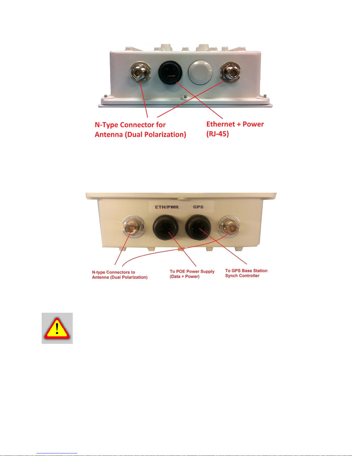
3.1 Port Description
SkyWay-EXCEL radio unit has the following access ports:
•(1) 10/100/1000 Gigabit Ethernet + Power Connector (XL250 PTP kit Series)
OR (1) 10/100/ Fast Ethernet + Power Connector (XL50 and XL100 PTP kit Series)
•(1) GPS port to be connected to a GPS controller (RJ-45 connector and CAT5e/6
cable) – GPS-Ready version of XL250 and XL100 only.
•(2) RF Ports: N type, female (Connectorized Master unit only – Slave units come with
integrated antennas)
The RJ45 connector is accessed at the bottom of the unit, through a multi-piece
waterproofing feed-through. If included, the RF Ports are accessed on the bottom of the unit,
which is shown below.
Unit Bottom View (Integrated antenna unit)
11
Unit Bottom View (Connectorized unit)
Unit Bottom View (GPS-ready version, shown with external connectors)
CAUTION - GPS-ready Master units have two RJ-45 ports. Make sure to connect
the GPS Sync Controller to the port labeled “GPS” and the radio POE to the port
labeled “ETH/PWR”. Reversing the connection will result in malfunction and
potential damage to the port.
12
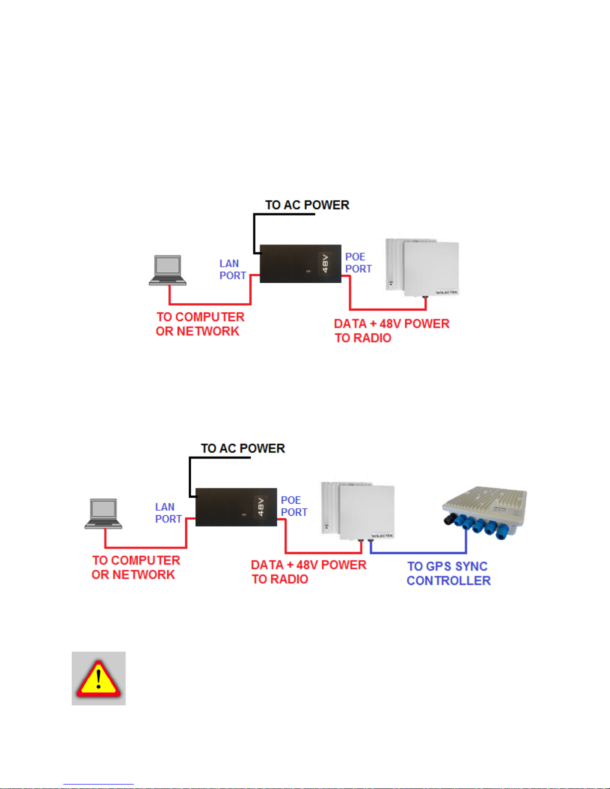
3.2 Connecting the SkyWay Unit to Network
Use the diagram below as a guide to cable your SkyWay test system using a PC or Laptop
and a pair of Cat5e/6 cables. An auto-MDIX feature eliminates the need for cross-over
cables.
C
ONNECTION
D
IAGRAM FOR
R
EGULAR
M
ASTER UNIT AND
S
LAVE UNITS
C
ONNECTION
D
IAGRAM FOR
GPS-R
EADY
M
ASTER UNIT
CAUTION - Before you connect a radio to a GPS controller, make sure to refer to
the documentation on the controller for proper connection practices. Improper
connections may lead to a malfunction or damage to the unit.

13
3.3 Initial Log-in
•Open networking properties in your Windows OS. Enter the TCP/IP setup window of
your wired Ethernet adapter properties page. Set the IP addresses to the following
values.
IP Address Setup on your Computer
Ethernet IP Address 192.168.1.1
Subnet Mask 255.255.255.0
•Open a Web Browser on the Test PC
At the URL line, type in the following:
Type of Unit Default IP Address
Slave Unit 192.168.1.100
Master Unit 192.168.1.200
NOTE – Depending on your computer OS, the above screen may look different.
Also, appearance of your GUI will depend on the type and version of your web
browser. Please contact Solectek sales and support for detailed information.
14
•The access username is admin and the default password is admin.
Default Radio Log-in Info
User Name admin
Password admin
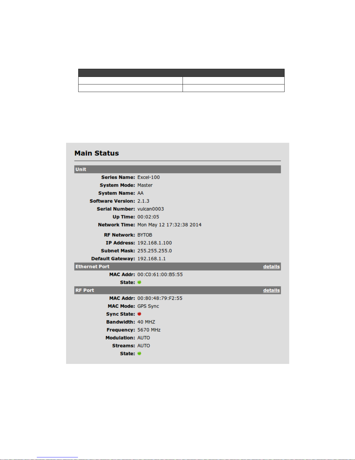
•Click OK on the above Windows screen and the Main Status screen will be displayed, as
shown below (Master unit version):

15
4. Bench testin
Before mounting units into their final location, it is recommended that the system be bench
tested to verify basic operation. The following bench test steps are suggested:
Setup. Each radio should be connected and configured per the previous Sections, with a laptop
or PC connected to each radio directly (or through a hub/switch).
NOTE – Make sure that Access Control MAC addresses are correct and that
units share the same bandwidth, data rate and security settings. Access Control
List (ACL) is enabled as a factory default setting.
It is also important to have identified and prepared the antenna, RF coax and Cat5 solutions that
will be used in the intended application.
Positioning. It is important to remember that the SkyWay radio and antenna system generate
and transmit a great deal of RF power. During bench testing, antennas should not be pointed
directly at each other. Rather, establish a position so there is approximately 180 degrees
angular separation and 6 to 10 feet between units. Fine tune the antenna position so that the
Local RSSI is between -30 and -60 dBm.
Testing. If the system has been properly configured, the radios will begin communicating
immediately. The following steps are recommended to verify operation:
•Link State. On the Main Status screen, verify that the RF Link State is Green
(connected).
•Local ping. From each laptop/PC be sure a ping to the local radio is successful.
•Link ping. Now ping from one laptop/PC to the other laptop/PC. This will verify the end-
to-end link.
•Traffic test. Using IPERF or equivalent utility, verify traffic can be passed successfully
across the link.

16
NOTE - Keep in mind that the SkyWay-Excel data rates will stress the
performance of the PC hardware, operating system and IP stack. To ensure that
this test equipment is not a performance bottleneck, pre-testing PCs, by connecting
them directly to each other, is strongly recommended.
NOTE -Using a file transfer to a shared volume or an FTP session on a typical
Windows/Intel machine is not adequate to accurately measure throughput.
NOTE -Units bench tested in an indoor configuration should not be
expected to deliver full rated throughput. Benchmarking is typically
performed after a system is deployed.
WARNING – When it is not in use, the GPS port of the GPS-ready Master unit
must be sealed to prevent water intrusion. The port is factory configured with a
sealing pin. Please leave it in place until you are ready to connect to a GPS
controller.
5. Physical Installation
5.1 Introduction
Your SkyWay radio is designed with a mounting system with two degrees of freedom. The radio
can be mast, tower, pole or wall mounted using the appropriate hardware. After determining the
best location for your radio, installation can begin.
To mount a SkyWay-Excel radio unit, both the mast mounting kit and Ethernet cable
feedthrough need to be correctly assembled. The recommended approach consists of 3 or 4
steps, detailed in the following sections:
•Ethernet cable / feedthrough assembly
•Bracket preparation
•Mounting
•Antenna mounting (for connectorized units, only)
17
With the exception of the CAT5 cable, all parts and hardware described in the following sections
are included with your SkyWay radio.
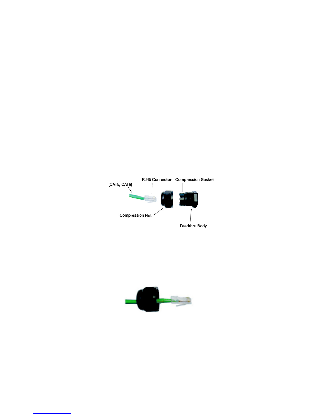
5.2 Ethernet Cable / Feedthrough Assembly
Only a single Ethernet cable is needed to connect the SkyWay radio to the indoor PoE Injector.
Since the cable is exposed to the outdoor elements (heat, moisture, and UV light), only outdoor
rated, shielded Cat5 Ethernet cable should be used. To ensure all-weather operation, the
weatherproofing cable feedthrough (also known as grommet or gland) must be properly
assembled onto the Ethernet cable and radio.
The following diagram depicts each of the feed-through parts:
Assembly Steps:
1. Remove the Compression Nut and slip it over the Ethernet CAT5 cable as shown below.
2. Feed the Ethernet CAT5 Cable through the Feedthrough Body (pre-installed on the
enclosure at the factory) and insert the RJ-45 connector to the female connector inside the
enclosure.
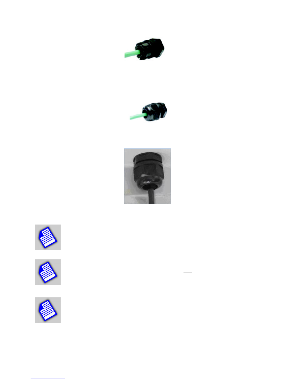
18
3. Install the Compression Nut and hand tighten until the cable resists slipping when gently
pushed or pulled. Lightly wrench-tighten, being careful not to overtorque the Compression
Nut.
The unit with properly installed feedthrough appears as follows:
NOTE - Removal of the RJ45 plug from the radio requires a tool such as a thin
screwdriver, or opened paperclip. Care must be taken not to damage the
Feedthrough Body or RJ45 plug.
NOTE - The total combined length of the Ethernet cables between the radio and
your network access device (hub/switch/PC) must not exceed 300 feet.
NOTE - Once mounted in a permanent location, additional weatherproofing tape
(included) should be applied around the assembled fitting to further enhance
durability.

19
5.3 Mounting Bracket and Tools
The following figure shows all components of the mounting kit.
The installation steps will be shown in the next section.
Tools necessary for tightening bolts and nuts are:
•10mm wrench for bolts to fasten the L-bracket to the radio enclosure
•13mm wrench for nuts to tighten U-bolt nuts.
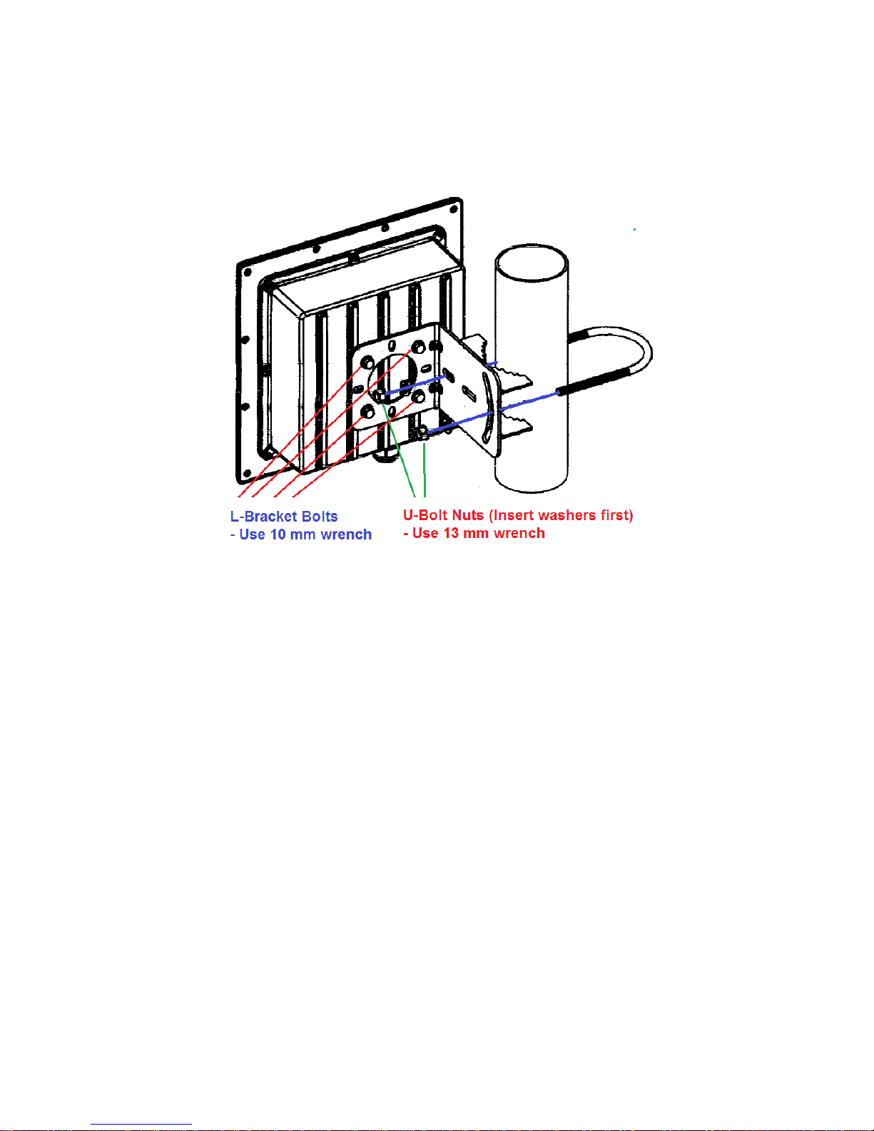
5.4 Unit Mounting
The final installation step involves mounting your SkyWay radio to an outdoor mast.
Refer to the following diagram to perform the installation steps:
•Fasten the L-bracket on the back of the radio enclosure. The hole patterns are
symmetric and you can rotate the enclosure by 90 degrees before installing the L-
bracket for establishing the radio link with horizontal polarization.
•Using the step bracket and U-bolt, fasten the L-bracket to the mast.
20
Azimuth alignment – Rotate the enclosure assembly in the horizontal direction
Vertical alignment - The L-bracket has a curved groove which can be used to tilt the enclosure
up or down.
Once the alignment is complete, tighten the bolts and nuts firmly.
5.3 Mounting of Separate Antennas
Tower or mast mounting of the antenna should proceed according to the antenna
manufacturer’s guidelines.
For interfacing to the Solectek radio, the following should be considered:
This manual suits for next models
12
Table of contents
Other Solectek Accessories manuals


Popular Accessories manuals by other brands

GAMERON
GAMERON WIRELESS SENSOR BAR FOR WII manual

WIKA
WIKA CPT2500 instruction manual

KooPower
KooPower DQ-608 user manual

Pepperl+Fuchs
Pepperl+Fuchs UC500-L2-E5-V15 manual

Revolution Lightning
Revolution Lightning RNET-OCC-HV-P-WS-J Specifications and installation

Visonic
Visonic DUO 200 installation instructions


