PVI 10kW / PVI 13kW / PVI 15kW Installation and Operation Manual
DOCR-060002 rev30 13 July 7, 2010
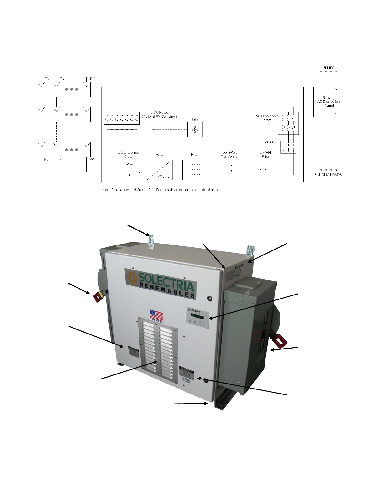
DC Wiring:
For the DC wiring without an integrated fused PV combiner, two conductors are required (one
for the grounded conductor and one for the ungrounded conductor) plus additional conductors for
grounds (see grounding section below). 90°C copper conductors must be used. The disconnect
terminals are listed for 75oC wire; see NEC 310.10 regarding temperature ratings of wire and terminals.
Torque terminal screws to 120 in-lb. Temperature derates, voltage drop and other considerations may
dictate that larger than minimum wire sizes be used. 2/0 AWG is the maximum size conductor that can
be landed in the terminals. Verify that any wire size choices meet local codes.
Inverter
Model Maximum DC
Input Current Number of DC
Conductors Minimum DC Wire Size
(at Max. DC Input Current) Maximum DC Wire
Size
10kW 52A 2 6 AWG, 90°C Cu 2/0 AWG, 90°C Cu
13kW 68A 2 4 AWG, 90°C Cu 2/0 AWG, 90°C Cu
15kW 77A 2 4 AWG, 90°C Cu 2/0 AWG, 90°C Cu
For the DC wiring with the optional integrated fused PV combiner, 10-14 total conductors are
required (one for the grounded conductor and one for the ungrounded conductor of each string) plus
additional conductors for grounds (see grounding section below). 90°C copper conductors must be
used. The disconnect terminals are listed for 75oC wire; see NEC 310.10 regarding temperature ratings
of wire and terminals. Ungrounded conductors (typically the positive DC conductors) are landed in the
touch-safe fuse holders; torque their terminal screws to 12 in-lb. Grounded conductors (typically the
negative DC conductors) are landed in the terminal block; torque their terminal screws to 35 in-lb.
Temperature derates, voltage drop and other considerations may dictate that larger than minimum wire
sizes be used. 2/0 AWG is the maximum size conductor that can be landed in the terminals. Verify that
any wire size choices meet local codes.
String Fuse Size Minimum DC Wire Size Maximum DC Wire Size
8A 12 AWG, 90°C Cu 8 AWG, 90°C Cu
10A 12 AWG, 90°C Cu 8 AWG, 90°C Cu
12A 12 AWG, 90°C Cu 8 AWG, 90°C Cu
15A 12 AWG, 90°C Cu 8 AWG, 90°C Cu
AC and DC Grounds, Including Equipment Grounding Conductors and Grounding Electrode
Conductors:
In accordance with local codes, specifically 690 NEC 2008, all grid-tie PV systems must have
the following:
DC Equipment Grounding Conductor (EGC)
DC Grounding Electrode Conductor (GEC) and DC Grounding Electrode
AC Equipment Grounding Conductor (EGC)
AC Grounding Electrode Conductor (GEC) and AC Grounding Electrode
In certain cases, local codes may allow for a common grounding electrode to be used for both the
AC and DC grounding electrode. In that instance, the grounding electrode conductor should be
connected to the AC ground bar in the AC disconnect. If required, additional ground lugs of the
appropriate size for the grounding conductors can be added in the disconnects and bonded to the existing
ground bar in a code compliant manner.
Connection Number of Open Positions Wire Range
DC Ground Bar 3 10 - 4 AWG, Cu
AC Ground Bar 3 10 - 4 AWG, Cu