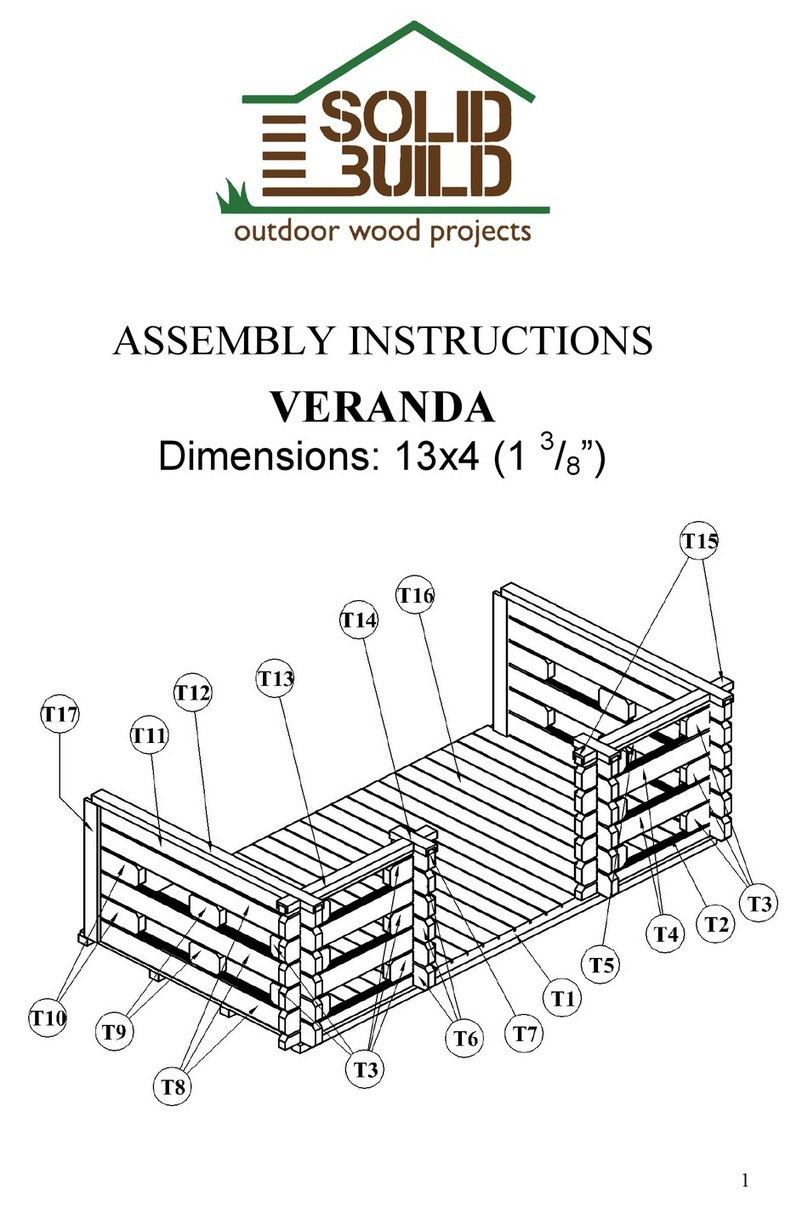
Solid Build MODERNA 2 User manual

ASSEMBLY INSTRUCTIONS
GARDEN SHED “MODERNA 2”
Dimensions: 13 x 10 (1 1/8’)’’
IMPORTANT
Before beginning the assembly of your garden shed, please read the instructions carefully
and follow them closely. By doing so, you will avoid unnecessary problems and save
time. It is recommended to start the assembly process only once all the components
of your shed have been identified, sorted, and classified by size.
This notice also contains recommendations related to maintenance of your shed.

GARDEN SHED –MODERNA2 13 x 10 (1 1/8’’)
2
WHAT YOU NEED TO KNOW BEFORE ASSEMBLY
Characteristics of wood. Wood has a set of specific traits that are natural and inherent
to it. Those characteristics include color, density, and the extent to which it is affected by
humidity.
Longitudinal cut, in most cases, reveals a delicate, decorative, and often very appreciable
look, which is called texture. In addition to that, wood has a specific smell, given by oils,
resins, and fermented substances.
A critical attribute of timber is the ease with which it absorbs humidity. When the timber
dries, it shrinks. Similarly, when timber absorbs humidity, it increases in volume. This
may reveal cracks in dry conditions and close them naturally in wet.
Downsides. One of the downsides of timber is that it chaps and warps. When the timber
dries, the moisture firstly evaporates from the surface and outer layers and only then from
the inside layers. Thus, when the outer layers start shrinking, the inside layers, due to
stronger moisture, oppose to shrinking. Firstly, the surface starts chapping, then the inside
layers follow. When the timber dries, it can get a longitudinal warp or a cross warp. A
longitudinal warp is when the drying straight balk bends, flat plank twists and gets the
form of the propeller. To avoid such warping, the wood should be restricted by binding
before it is exposed to temperature and humidity variations. Wood has a set of specific
technological characteristics. It easily splits along the fiber, nicely holding metal
fastenings; it can flex easily and is not very sensitive to depreciation. Screws hold timber
exceptionally well. Screws have a much better grip with timber than nails.
Taints: branchy timber, cracks, abnormal structure, infractions made by fungus or
parasites. As timber is of biological origin, it is so varied that the terms “normal timber”
and “abnormal timber” are not strictly defined. Within the variety of sawn wood and sawn
timber, some taints due to fungus may occur, such as mold or brownness. Mold generally
does not affect physical and mechanical characteristics of timber.
When timber is affected bybiological (fungus), physical (environmental, temperatureand
humidity) and chemical factors, it decomposes.
Timber may last a long time, but fluctuations in humidity and temperature of the
environment reduce its longevity. A variety of cracks may emerge, which then both
damage the integrity of the timber and facilitate infection with (and rapid development
of) fungus. Generally speaking, the older the tree, the better the durability of its lumber.
The most effective way to protect the wood from insects and decay is to treat it with
substances which are toxic to fungus and insects. It may be natural or chemical
substances.

GARDEN SHED –MODERNA2 13 x 10 (1 1/8’’)
3
Protection. Assembling the shed should be carried out in dry weather conditions. If rain
should start during the assembly process, the wood must be covered to avoid warping.
Once you have erected the shed, let it settle for a couple of days and finish with a coat of
paint, stain or other appropriate treatment. If you wish to paint or treat your shed sooner,
stomp your feet on the roof to help it settle faster. Make sure there are no unembedded
tongues and grooves as warping may occur when moisture is applied.
Foundation. Before erecting the shed, it is essential to make a firm and plain foundation,
ideally using concrete, concrete slabs, or concrete blocks. Pressure-treated wood grid is
an excellent choice for stiffer soil. It is crucial to have the foundation corners at right
angles and completely level.
ATTENTION: You will find boards for hammering the wall-boards in the package. Do
not hit the wall board using only the hammer. Please follow the instruction in the
picture below or use a rubber mallet.

GARDEN SHED –MODERNA2 13 x 10 (1 1/8’’)
4
PREPARATION OF ASSEMBLY
Tools needed for assembly:
•Rubber mallet
•Hammer
•Tape measure
•Pliers for removing staples
•Philips screwdriver
•5M Allen wrench for hinge adjustment
•Ladder
•Drill (optional)
NOTE! You must build a foundation and acquire floor joists if installing any type of
floor. If building on concrete slab, you may leave the concrete to serve as the floor;
however, it is advised to start with a pressure-treated wood frame perimeter, so the
raw wood does not come in direct contact with soil.

GARDEN SHED –MODERNA2 13 x 10 (1 1/8’’)
5
STARTER WALL BOARDS
POSITION
DESIGNATION
DIMENSION (inch)
QUANTITY
1
Nicked lower starter front
wall-board
117.32 x 2.16 x 1.1
1
2
Lower back wall-board
117.32 x 2.16 x 1.1
1
3
Side wall-board
117.32 x 4.33 x 1.1
32 + (1*)
To form the core framework, begin with a nicked lower starter front wall-board (part
no. 1), a lower back wall-board (part no. 2) and side wall-boards (part no. 3) ensuring
the lock of corners and positioning the groove of a wall-boards to the bottom and the
tongue to the top. Check for squareness by measuring the diagonal distance. Shift the
corners until you get even distance between the opposite corners.
Anchor treated floor joists to concrete using concrete anchors (notprovided),then fasten
two lower boards to the treated floor joists using wood screws. If not using floor joists
supplied, secure the lower wall boards directly to your foundation.
To anchor your shed, fasten lower wall boards using long wood crews (not provided) to
the floor joists. Screw through the tongue 2-3 inches away from the corner joint or
predrill and screw through the joint. Predrilling is necessary if screwing the joint as
the wood is thinner there and may split upon screw insertion.
From there on, you won’t need screws for the rest of the wall boards.
NOTE!You may have through screws and nails.

GARDEN SHED –MODERNA2 13 x 10 (1 1/8’’)
6
ASSEMBLY OF WALLS
POSITION
DESIGNATION
DIMENSION
(inch)
QUANTITY
4
Front wall-board
30.70 x 4.33 x 1.1
34
5
Back wall-board
117.32 x 4.33 x 1.1
19 + (1*)
6
Short side wall-board
12.20 x 4.33 x 1.1
8
7
Intermediate side wall-
board
7.24 x 4.33 x 1.1
8
Continue with front wall-boards (part no. 4), side wall-boards (part no. 3), and back
wall-boards (part no. 5) until the 3rd –4th level of side walls.
It’s easier to install the door and windows when you only have assembled first 3-4
layers of boards, in that case, you do not need to lift the assembled door or window
frame very high.
NOTE! If installing an add-on window, check thewindow installation instructions now.

GARDEN SHED –MODERNA2 13 x 10 (1 1/8’’)
7
INSTALLING DOOR FRAME
POSITION
DESIGNATION
DIMENSION (inch)
QUANTIT
Y
9
Lower strip of double door
(horizontal)
55.51 x 2.95 x 2.59
1
10
Side strip of double door
(vertical)
76.37 x 3.54 x 2.59
2
11
Top strip of double door
(horizontal)
55.51 x 3.54 x 2.59
1
It is time to install (slide in) the double door frame (part no. 9, 10, 11). First build the
frame for the double door made from the lower strip of the door (part no. 9), the side
strips of the door (part no. 10), and the top strip of the door (part no. 11) with four
0.19x3.54 inch screws into the pre-drilled holes, 1 at each corner. Make sure to screw
them all the way in, inside the U-shaped groove.
OPTIONAL. Fasten the four frame strips with metal L-brackets, fix them with eight
0.12x1.20 inch screws, 1 at each corner. The brackets help keep the right angle during
the installation.
Slide the door frame through the top into the opening in the wall, hinges facing outside.
Install the double door (part no.12) by hanging panels on the hinges.
DO NOT fasten the door frame to the wall boards.

GARDEN SHED –MODERNA2 13 x 10 (1 1/8’’)
8
FIXING THE DOOR
OPTIONAL. Install 2 barrel bolts to the door outside as pictured above. Fix them with
4 screws 0,118x0,984. You may install one at the bottom, and one at the top, or only
one at the bottom.
NOTE. This adds security and prevents the door from potential warping if the extreme
temperature or humidity fluctuations are frequent in your area. E.g. dew forms on the
shed overnight and the shed door is facing sun in the East with no shade. The sun creates
extreme heat over the wet wood; thus, the exterior layers of wood dry out faster than
the deeper layers, and the wood starts to warp unless it is restricted.

GARDEN SHED –MODERNA2 13 x 10 (1 1/8’’)
9
ASSEMBLY OF WALLS AND PILLARS
POSITION
DESIGNATION
DIMENSION (inch)
QUANTITY
8
Window
24.56 x 29.48
3
9
Lower strip of double door
(horizontal)
55.51 x 2.95 x 2.59
1
10
Side strip of double door (vertical)
75.19 x 3.54 x 2.59
2
11
Top strip of double door (horizontal)
55.51 x 3.54 x 2.59
1
12
Double door
69.88 x 26.96
1+1
13
Gable
117.32 x 4.33 x 1.1
2
14
Pillar
79.53 x 4.33 x 4.88
2
15
Beam of pillar
130.71 x 5.51 x 1.73
1
16
Nicked front wall-board
168.90 x 6.49 x 1.1
1
17
Nicked top back wall-board
168.90 x4.33 x 1.1
1
Continue mounting walls with intermediate side wall-boards (part no. 7), short side
wall-boards (part no. 6) and back wall-boards (part no. 5) till the 18th level of side
walls and slide in the windows (part no. 8) into the openings.
NOTE. You can form window openings on any of the three walls, as low or as high as
you like.
Now, you can position the prefabricated gable (part no. 13).
Fasten pillars (part no. 14). Fix pillars with fasteners to your foundation or concrete
piers (fasteners aren’t included; use same as for shed anchoring). Fasten beam of pillar
(part no. 15) with two 0.19x2.75”screws, 1 at each corner and place nicked front wall-
board (part no. 16). Fasten nicked top back wall-board (part no. 17) with two
0.19x2.75”screws, 1 at each corner.

GARDEN SHED –MODERNA2 13 x 10 (1 1/8’’)
10
CORNER REINFORCEMENT STUDS
Fasten the corner plates to the walls to create a pocket and slide in each stud through
the top.
OPTIONS. Use either 3 or 4 corner plates to create the pockets. You can also install
the studs only at the front, the rear ones are not essential, especially when building on
a concrete slab. If you prefer, install the corner studs on the outside!
The corner studspreventthe walls from bowing out in the future. Space out thebrackets
to form the pocket and slide/hammer the stud from the top. Leave some room at the
bottom to fit the floorboards and baseboard. Do not screw the studs until your floor
is done and the roof is covered as the whole structure will settle from the weight of the
roof. Once all that is done, screw the screws into the sliding slot near the center of the
slot - do not overtighten - this allows the structure to expand and contract as the
seasons change. ** Facade may vary **
POSITION
DESIGNATION
DIMENSION (inch)
QUANTITY
25a
Corner Stud
76,77 x 1.57 x 1.57
4
25a
Ø 0,31x0,13x0,13 inch
12-16 units
Ø 0,12x0,12 inch
48 units
Ø M6
16 units
Ø0,15x1,5 inch
16 units

GARDEN SHED –MODERNA2 13 x 10 (1 1/8’’)
11
FINISHING THE WALLS
POSITION
DESIGNATION
DIMENSION (inch)
QUANTITY
18
Sustaining front fascia-board
16.53 x 4.33/4.21 x 1.73
2
19
Sustaining back fascia-board
16.53 x 2.28/1.93 x 1.73
2
20
Front part of gable
37.12 x 4.33/3.77 x 1.1
2
21
Back part of gable
37.12 x 2.67/1.93 x 1.1
2
22
Top front wall-board
0!
Now, you can position the sustaining fascia-board (part no. 18 and 19) with 0.19x2.75
inch screws. Place parts of gable (part no. 20 and 21) and fasten top front wall-board
(part no. 22) with two 0.19x2.75 inch screws, 1 at each corner.

GARDEN SHED –MODERNA2 13 x 10 (1 1/8’’)
12
ASSEMBLING ROOF BEAMS
Fixing of protective wind studs
Pic. 1
Fix the protective wind
studs to the gable with
0.23x2.3 inch screw in
the middle of groove
Pic. 2
Fix the protective wind
studs to the lower wall-
board with a 0.15x1.5 inch
screw.
POSITION
DESIGNATION
DIMENSION
(inch)
QUANTITY
23
Beams
168.90 x 5.51 x 1.73
3
24
Front protective wind studs
82.67 x 1.57 x 0.62
2
25
Back protective wind studs
80.70 x 1.57 x 0.62
2
When the gable is well positioned, the beams (part no. 23) can be installed. Fix them to
the gable with 0.19x2.75 inch screws.
Strengthen the construction with protective wind studs (part no. 24 and 25) as shown
in figure 1 and 2 by drilling through the wall at the top. Finger tighten only so the washer
can spin easily to allow the wood to retract and expand. Make sure the top of the wind
stud is at least 1” below the roofline.
NOTE. The protective wind studs can also be installed from the outside of a shed
or skipped if you live in a low wind area.
Check if the door closes properly. At this time, you can still shift the whole structure
by pushing to the sides as needed to square the door frame. The structure will lock once
you install the roof boards. If the door still "sticks" at the top or bottom, adjust the hinges
using an Allen wrench. You can shift the angle and height of the door by adjusting the
hinges on the door panels.

GARDEN SHED –MODERNA2 13 x 10 (1 1/8’’)
13
INSTALLING THE ROOF BOARDS
POSITION
DESIGNATION
DIMENSION
(inch)
QUANTITY
26
Roof board
125.98 x 3.46 x 0.7
49+ (2*)
Ensure that walls are assembled correctly. Start covering the roofwith roof boards (part
no. 26). Begin at one side, 3.34” end facing the front/back, nail or screw the roof boards
at each point they meet the beam or wall. The roof board ends have to be flush with the
beams at the front. Continue all the way to the other side. You may need to cut the last
board narrow to make it flush with the beam on the other side as well.
NOTE! If you are assembling your shed during prolonged dry weather conditions, it is
recommended to leave a gap of about 1/16 inch between each roof board, thus allowing
the wood to take its normal position in wet period.

GARDEN SHED –MODERNA2 13 x 10 (1 1/8’’)
14
INSTALLING FASCIA
POSITION
DESIGNATION
DIMENSION (inch)
QUANTITY
27
Front and back fascia-boards
170.39 x 8.66 x 0.74
2
28
Side fascia
130.70 x 8.66 x 0.74
2
29
Top front fascia
170.39 x 3.54 x 0.74
1
30
Top side fascia
128.66 x 3.54 x 0.74
2
31
Roof end boards
10.23 x 1.57 x 0.62
2
32
Roof end boards
35.24 x 1.57 x 0.62
6
33
Roof end boards
48.43 x 1.57 x 0.62
2
Before installing the chosen roofing, fix fascia (part no. 27, 28, 29 and 30) to the sides
of roofing with screws as shown in the image above. Roof end boards (part no. 31, 32
and 33) should be fixed to ends of roof boards under the front and back fascia. Attach
the fascia flush with the roof boards but covering the roof board ends - your roofing
material has to extend over them. Drip edge is optional but recommended. You may
install it as you start the roofing.
Only fix the top fascia (part no. 29 and no. 30) if using bitumen roofing and no shingles.
Attach it on top of the finished roof to form a corner with the vertical fascia.

GARDEN SHED –MODERNA2 13 x 10 (1 1/8’’)
15
LIST OF ALL PARTS OF THE LOG CABIN
POSITION
DESIGNATION
DIMENSION (inch)
QUANTITY
1
Nicked lower starter front wall-board
117.32 x 2.16 x 1.1
1
2
Lower back wall-board
117.32 x 2.16 x 1.1
1
3
Side wall-board
117.32 x 4.33 x 1.1
32 + (1*)
4
Front wall-board
30.70 x 4.33 x 1.1
34
5
Back wall-board
117.32 x 4.33 x 1.1
19 + (1*)
6
Short side wall-board
12.20 x 4.33 x 1.1
8
7
Intermediate side wall-board
7.24 x 4.33 x 1.1
8
8
Window
24.56 x 29.48
3
9
Lower strip of double door (horizontal)
55.51 x 2.95 x 2.59
1
10
Side strip of double door (vertical)
75.19 x 3.54 x 2.59
2
11
Top strip of double door (horizontal)
55.51 x 3.54 x 2.59
1
12
Double door
69.88 x 26.96
1+1
13
Gable
117.32 x 4.33 x 1.1
2
14
Pillar
79.53 x 4.33 x 4.88
2
15
Beam of pillar
130.71 x 5.51 x 1.73
1
16
Nicked front wall-board
168.90 x 6.49 x 1.1
1
17
Nicked top back wall-board
168.90 x 4.33 x 1.1
1
18
Sustaining front fascia-board
16.53 x 4.33/4.21 x 1.73
2
19
Sustaining back fascia-board
16.53 x 2.28/1.93 x 1.73
2
20
Front part of gable
37.12 x 4.33/3.77 x 1.1
2
21
Back part of gable
37.12 x 2.67/1.93 x 1.1
2
23
Beams
168.90 x 5.51 x 1.73
3
24
Front protective wind studs
82.67 x 1.57 x 0.62
2
25
Back protective wind studs
80.70 x 1.57 x 0.62
2
26
Roof board
125.98 x 3.46 x 0.7
49+ (2*)
27
Front and back fascia-boards
170.39 x 8.66 x 0.74
2
28
Side fascia
130.70 x 8.66 x 0.74
2
29
Top front fascia
170.39 x 3.54 x 0.74
1
30
Top side fascia
128.66 x 3.54 x 0.74
2
31
Roof end boards
10.23 x 1.57 x 0.62
2
32
Roof end boards
35.24 x 1.57 x 0.62
6
33
Roof end boards
48.43 x 1.57 x 0.62
2
25a
Corners beam
76,77 x 1,57 x 1,57
4
BOLTS
SCREWS
NAILS
4 units
Protective wind studs
(Ø 0.23x2.3 inch)
(Ø 6x60mm)
10 units
Finish door
(Ø 0.15x1.96 inch) (Ø 4x50
mm)
280
units
Roof board,
(Ø 0.08 x 1.57 inch)
(Ø 2 x 40mm)
4 units
Protective wind studs,
(Ø M6)
110 units
Fascia, protective wind
stud,met.angles for
reinforcement beams
(Ø 0.15x1.5 inch) (Ø 4x40 mm)
OTHER
24 units
Protective wind
studs,reinforcement
(Ø M6)
20 units
Top wall-board, beam,
sustaining fascia-board
(Ø 0.19x2.75 inch) (Ø 5x70
mm)
4 units
L-Brackets for door
frame (optional)
16 units
Angles
(0,31x0,13x0,13inh)
(80x35x35)
103 units
Roof end board,met.angles for
door strips
(Ø 0.12x1.2 inch) (Ø 3x30mm)
2 units
SCREW Fix the
door
(Ø 0.118 x 0,984)
(Ø 3 x 25mm) 8units
*The number in brackets shows the number of existing spare parts.
Table of contents
Other Solid Build Garden House manuals
Popular Garden House manuals by other brands
Lemeks
Lemeks Palmako LA28-3021 Assembly, installation and maintenance manual
OLT
OLT FL Bevel Assembly manual

Tiger
Tiger MAYFLOWER SUMMERHOUSE Assembly instructions

Palmako
Palmako Schonheim 1.5 FR40-3636 installation manual

total sheds
total sheds Pent Shed Assembly manual
Duratuf
Duratuf Sentry SG3030 Assembly instructions

Mercia Garden Products
Mercia Garden Products 0644CSNE0404HGDD2SW-V1 Assembly instructions

Palmako
Palmako Britta installation manual

Palmako
Palmako PA44-3535 manual

USP
USP DURAMAX 10Ft x 12Ft Eco owner's manual
Karibu
Karibu BASTRUP-7 73306 Building instructions
Palmako
Palmako FRF28-4132 installation manual
