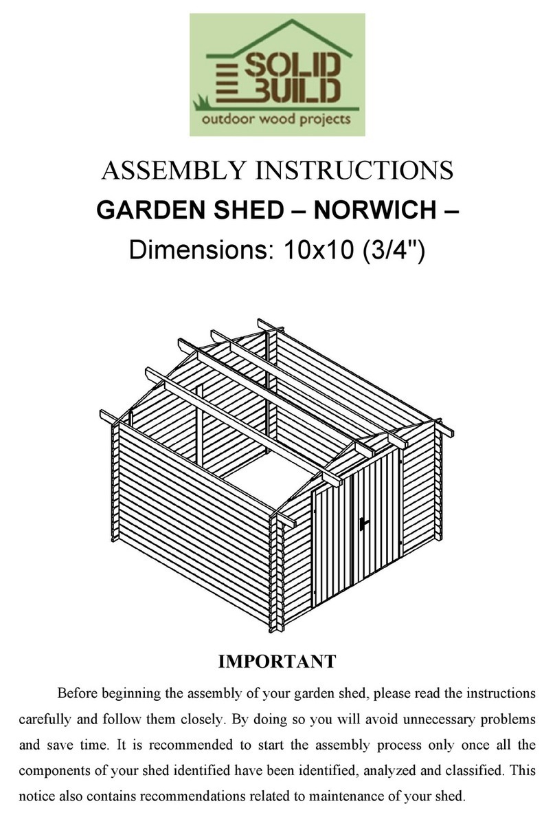
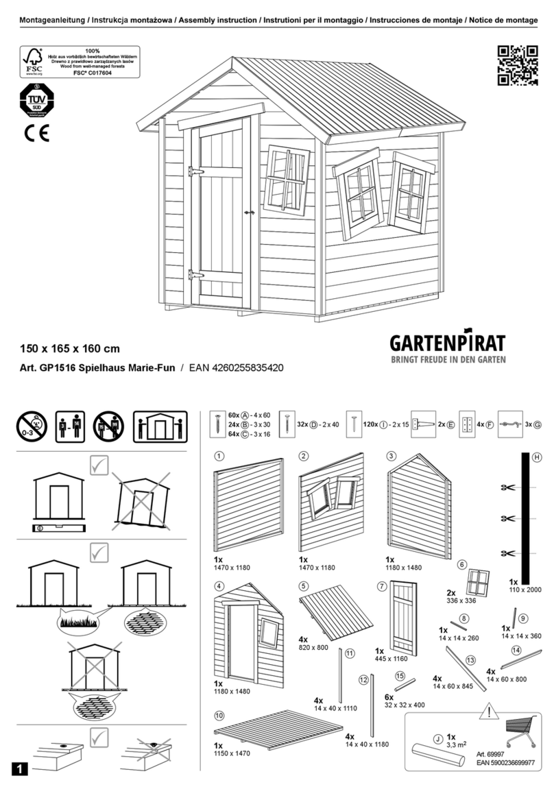
Solid Build BRIGHTON User manual

ASSEMBLY INSTRUCTIONS
BRIGHTOLN GARDEN SHED
10 ft x 10 ft, 1 3/8"
IMPORTANT
Before beginning the assembly of your SolidBuildTM garden shed, please read
the instructions carefully and follow them closely. By doing so, you will avoid
unnecessary problems and save time.
It is recommended to start the assembly process only once all the components of
your shed have been identified, sorted, and classified by size. This intro also
contains recommendations related to the maintenance of your shed.

What you need to know before assembly
CHARACTERISTICS OF WOOD. Wood has a set of specific traits that are
natural and inherent to it. Those characteristics include color, density, and the extent
to which it is affected by humidity.
Longitudinal cut, in most cases, reveals a delicate, decorative, and often very
appreciable look, which is called texture or wood grain. In addition to that, wood has
a specific smell, given by oils, resins, and fermented substances.
A critical attribute of timber is the ease with which it absorbs humidity. When
the timber dries, it contracts. Similarly, when timber absorbs humidity, it increases in
volume. This may reveal cracks in dry conditions and close them naturally in wet.
The contraction and expansion is mostly observed vertically, thus binding the
wall boards vertically from top to bottom is not advised as that will obstruct the
natural cycle of wood and cause structural issues.
WHY DOES WOOD WARP. When the timber dries, the moisture firstly
evaporates from the surface and outer layers and only then from the inside layers.
Thus, when the outer layers start shrinking, the inside layers, due to stronger moisture,
oppose to shrinking. Firstly, the surface starts chapping, then the inside layers follow.
When the timber dries, it can get a longitudinal warp or a cross warp. A longitudinal
warp is when the drying straight balk bends, flat plank twists and gets the form of the
propeller. To avoid such warping, the wood should be restricted by binding before it
is exposed to temperature and humidity variations. Sudden exposure to sun or rain
will cause the wood to warp.
TIP: cover the wood as soon as possible after the delivery and before the
assembly to help protect it from temperature and humidity variations.
IS THIS BOARD DEFECTIVE? As timber is of biological origin, it is so
varied that the terms “normal timber” and “abnormal timber” are not strictly defined.
Within the variety of sawn wood and sawn timber, some taints are to be expected,
such as branchy timber, cracks, natural longitudinal splits, sap, texture and grain
variations. If the board is not broken, it is most likely not defective. Please see page
5 for a list of acceptable variations.
BRIGHTON 10 ft x 10 ft, 1 3/8"

FOUNDATION. Before erecting the shed, it is essential to make a firm and
level foundation. It is crucial to have the foundation corners at right angles and
completely level. Common foundation options are concrete slab pavers, treated wood
grid on cement blocks or concrete piers, gravel pad within treated wood frame, etc.
PROTECTION. Assembling the shed should be carried out in dry weather
conditions. If rain should start during the assembly process, the wood must be covered
to avoid warping. Once you have erected the shed, let it settle for a couple of days and
finish with a coat of paint, stain or other appropriate treatment. Make sure there are
no unembedded tongues and grooves at the time of treatment as warping may occur
when moisture is applied.
The most effective way to protect the wood from insects and decay is to treat it
with substances that are toxic to fungus and insects. It may be natural or chemical
substances.
ATTENTION: You will find boards for hammering the wall-boards in the
package. Do not hit the wall board using only the hammer. Please follow the
instruction in the picture below or use a rubber mallet.
BRIGHTON 10 ft x 10 ft, 1 3/8"

BRIGHTON 10 ft x 10 ft, 1 3/8"

TYPE PLACE
VARIATION
ACCEPTABLE UNACCEPTABLE
CRACKS
COATING
CRACKS
MAX WIDTH: 1/8”, PASSES
THROUGH THE INSERT
WIDTH EXCEEDS 1/8”
BOARD
SURFACE
CRACKS
MAX WIDTH: 1/8”,
MAX LENGTH: 30% OF THE
ENTIRE LENGTH OF THE
BOARD
WIDTH EXCEEDS 1/8”,
LENGTH EXCEEDS 30% OF THE
ENTIRE LENGTH OF THE BOARD
CRACKS AT
THE END OF
THE BOARD
–
ENTERS THE INSIDE OF THE NOTCH
RESIN GAPS
ALL
WOODEN
PARTS
MAX WIDTH: ¼”,
MAX LENGTH 3”
WIDTH EXCEEDS ¼”, LENGTH
EXCEEDS 3”
OTHER WOOD
DEFECTS
ALL
WOODEN
PARTS
HAVING A DIRECT IMPACT TOWARDS
THE MECHANICAL CHARACTERISTICS
OF THE BOARD
5
BRIGHTOLN 10 x 10 ft, 1 3/8"
LIST OF ACCEPTABLE DEFECTS

TYPE PLACE ACCEPTABLE UNACCEPTABLE
HOLEY
KNOTS ALL WOODEN PARTS
MAX: 50% OF THE KNOT
SURFACE
EXCEEDS 50% OF
THE KNOT SURFACE
FALLEN OUT
KNOT WITHIN
THE MALE
CONNECTION
WALL AND ROOF
BOARDS.
LIGHT DOES NOT PROTRUDE
FOLLOWING ASSEMBLY
LIGHT DOES PROTRUDE
FOLLOWING ASSEMBLY
FALLEN OUT
KNOT WITHIN
THE FEMALE
CONNECTION
WALL AND ROOF
BOARDS.
LIGHT DOES NOT PROTRUDE
FOLLOWING ASSEMBLY
LIGHT DOES PROTRUDE
FOLLOWING ASSEMBLY
MECHANICAL
CRACKS
DOORS, WINDOWS,
SURFACES AROUND THE
HANDLE, SHUTTERS,
PLANTERS
–
NOT ACCEPTABLE
FALLEN OUT
KNOT
ROOF BOARDS AND
OTHER ACCESSORIES
Acceptable only in cases where
bituminous felting is applied NOT ACCEPTABLE
6
BRIGHTOLN 10 x 10 ft, 1 3/8"
LIST OF ACCEPTABLE DEFECTS

CRACKS ON
TIMBER
Only cracks that may
have an impact on the
robustness of the
construction shall be
considered as defects.
Wood is a natural and living material whose dimensions, appearance, weight and shape are subject to changes. All of the
above-mentioned aspects do not have any impact towards the characteristics, functionality and quality of the product.
Some characteristics of the wood shall not be held as grounds for exchanging of parts.
DEFORMED
TIMBER
Only parts that are not possible to be installed utilizing clamps shall be considered as defects.
DEFECTIVE
PARTS
APPEARANCE
The above-mentioned defects are considered as tolerable. The manufacturer recommends sanding and
cleaning resin pockets using a spatula. All of the defects that are not visible following the assembly of
the house are deemed to be acceptable.
OK
TYPE PLACE ACCEPTABLE UNACCEPTABLE
DEFECT
7
BRIGHTOLN 10 x 10 ft, 1 3/8"
LIST OF ACCEPTABLE DEFECTS

BRIGHTON 10 ft x 10 ft, 1 3/8"
PREPARATION OF ASSEMBLY
Tools needed for assembly
•Rubber mallet
•Hammer
•Tape measure
•Pliers for removing staples
•5M Allen wrench for hinge adjustment
•Ladder
•Drill
•Handsaw
FOR INSTRUCTIONAL VIDEO CLIPS, GO TO :
shorturl.at/ejvzT, or scan the QR code (opens YouTube playlist)

LIST OF ALL PARTS
Pos. Quantity Dimension, mm Details
A B C
1x 7 109 1/22 3/81 1/2
2 x 2 117 3/82 5/81 3/8
3 x 19 117 3/85 3/81 3/8
4x 14(+1) 117 3/85 3/81 3/8
5 x 28 13 5 3/81 3/8
6x 12 31 7/85 3/81 3/8
7a x 1 90 1/24 3/42 7/8
7b x 2 78 1/84 3/42 7/8
7c x 2 69 1/44 3/42 7/8
7d x 1 90 1/24 3/42 7/8
8x 1 129 1/85 3/81 3/8
9x 1 137 5 3/81 3/8
10 x 1 43 3/45 3/81 3/8
11 x 1 51 1/25 3/81 3/8
12 x 1+1 152 3/45 3/81 3/8
13 x 1 116 3/421 1 3/8
14 x 1 116 3/421 1 3/8
15 x 2 152 3/45 1/21 3/4
16 x 1 152 3/45 1/21 3/4
17 x 4 78 3/41 1/25/8
18 x88(+2) 65 3 1/23/4
19 x 4 66 1/243/4+31/23/4
20 x 4 76 3/81 1/25/8
21 x 2 8 5/843/4
B
C
A
A
A
A
A
A
A
B
C
C
A
B
C
A
A
B
B
C
B
C
A
A
A
C
B
B
B
C
B
C
A
B
A
A
A
A
A
A
A
A
B
B
C
B
C
B
C
BRIGHTON 10 ft x 10 ft, 1 3/8"

LIST OF ALL PARTS
Pos. Quantity Dimension, mm Details
A B C
22 x 1+1 26 69 7/8
23 x 2 17 1/269 1/4
24 x 1 55 1/240 3/4
25 x 31(+2) 70 7/83 1/23/4
26 x 31(+2) 35 1/23 1/23/4
27 x 8 53 3/81 1/83/4
28 x 4 77 1/21 1/21 1/2A
A
B
B
C
AB
C
B
C
A
A
B
A
B
5x90 mm 4x40 mm M6 2x40 mm
x 14 x 42 x 4 x 570
5x70 mm 3x30 mm M6 Barrel Bolt Window Hardware
x 18 x 68 x 24 x 2 x 3
3x25 mm 6x160 mm 6x70 mm Door Handle Lock Cylinder
1”
x 8 x 6 x 4 x 1 x 1
3”
BRIGHTON 10 ft x 10 ft, 1 3/8"

11
1
STEP 1 - PREPARATION OF ASSEMBLY
OPTIONAL! Put plywood subflooring to match the perimeter of the foundation. It
adds additional stability and prevents the floor from sagging in the coming decades
as well as isolate the potential rotting from below.
NOTE: if building on a treated wood grid or plywood covered platform, you don’t
have to use the treated foundation beams at all. Just start building directly on your
foundation platform.
BRIGHTOLN 10 x 10 ft, 1 3/8"
Position Dimension (in)Quantity
1109 3/8 x 2 3/8 x 1 1/27

Please note - all sheds should be assembled on a level and firm foundation.
Sort all the parts by length and appearance, determine their designation
before assembly. It saves a lot of time during the assembly!
1. Set up the floor joists (POS. 1). Space them out as indicated on the floor joist
diagram in your assembly manual. Set the stater row (POS. 2 & POS. 3) on the
floor joists to help align them properly.
2. Make sure the starter rectangle is at right angles by measuring the diagonal
distance. The measurements should be equal. Push the corners until you get even
measurements. Then, carefully remove the starter boards and set them aside.
3. For installation on a concrete foundation, double-check the floor joists are level
and anchor them using concrete screws every 18" – 24".
Concrete screws or anchors can be purchased at your local hardware store.
4. If your foundation consists of a pressure-treated wood grid, omit the floor joists
supplied and install the starter boards directly on the foundation.
OPTIONAL. For added support, you may install a plywood subfloor on the floor joists
or wood foundation before fastening the starter boards.
STEP 1 - PREPARATION OF ASSEMBLY
12
BRIGHTOLN 10 x 10 ft, 1 3/8"

13
1
FLOOR JOIST DIAGRAM
Position Dimension (in)Quantity
1109 3/8 x 2 3/8 x 1 1/27
BRIGHTOLN 10 x 10 ft, 1 3/8"

15
STEP 3 - ANCHOR BOTTOM SIDE WALL BOARDS (OPTIONAL)
6x160mm
x6
3
Position Dimension (in)Quantity
32
117 3/8 x 5 1/4 x 1 3/8
BRIGHTOLN 10 x 10 ft, 1 3/8"

1. Return the starter boards (POS.2 & POS. 3) on the floor joists, and double-check
that starters are at right angles.
2. Fasten the starter boards to the floor joists using the wood screws provided. To
anchor your shed, fasten each starter wall board using 3 long 31/2" wood screws to
the floor joists.
3. Front and back start boards (POS. 2) are fastened at the joint and center through
the tongue. Predrilling is necessary when screwing at the joint as the wood is
thinner and may split upon screw insertion.
4. Side starter wall board (POS. 3) fixing is OPTIONAL. You may fasten the side
wall boards to the floor joists or foundation using 3 extra-long 51/2" wood screws.
Predrill, and use a driver-drill in this case.
TIP. For added support, you may install a plywood subfloor on the floor joists or wood
foundation before fastening the starter boards.
From there on, you won't need screws for the rest of the wall assembly.
TRICK
To ensure the starter row is square (at right angles), use a piece of factory-cut plywood or
another large item with at least one 90-degree corner. Place this item in the corner of the
starter rectangle to help align the boards, mark the proper location and have your build
partner align the opposite corner while you are holding the first one.
This may be easier than measuring cross distances between corners when the foundation
outline is not clearly defined.
STEP 2 & 3 - ANCHOR STARTER ROW
16
BRIGHTOLN 10 x 10 ft, 1 3/8"

17
Position
Dimension (in)
Quantity
3 19
414(+1)
5
13 x 5 3/8 x 1 3/8
28
6
31 7/8 x 5 3/8 x 1 3/8
12
7a
90 1/2 x 4 3/4 x 2 7/8
1
7b
78 1/8 x 4 3/4 x 2 7/8
2
7c
69 1/4 x 4 3/4 x 2 7/8
1
7d
90 1/2 x 4 3/4 x 2 7/8
1
23
17 1/2 x 69 1/4
2
STEP 4 - ASSEMBLE WALLS AND DOOR FRAME
Lay out all the door frame and window combo parts.
Check door hinge direction against the door panels.
Slide the assembled frame into the front wall opening.
DO NOT HANG DOOR PANELS NOW.
1. Screw 7b and 7c to 7a;
2. Slide in the tall windows;
3. Screw the 7d to 7b and 7c;
117 3/8 x 5 1/4 x 1 3/8
117 3/8 x 5 1/4 x 1 3/8
34
3
5x90mm
x4
7d
7a
7b
7b
5
5
5x90mm
x4
7c
23
BRIGHTOLN 10 x 10 ft, 1 3/8"

1. Continue assembling front wall-boards (POS. 5), back wall-boards (POS. 4), and
side wall-boards (POS. 3) up to the 4th level of side walls.
2. Build the frame for the double door & window combo made of the lower strip of
the door (POS. 7a), the side strip of the door (POS. 7b), the top strip of the door
(POS. 7d) and the inside strips of a double door (POS. 7c).
3. Lay out all the door frame and window combo parts on the ground.
4. Check door hinge direction against the door panels - aluminum threshold sits at the
bottom, and hinges face outside.
5. Using long wood screws provided, screw frame pieces at the predrilled holes at
each corner and inner frame strips. Make sure the screws go all the way into the
U-shaped channel.
a. Screw POS. 7b and POS. 7c to POS. 7a;
b. Slide in the tall windows;
c. Screw the POS. 7d to POS. 7b and POS. 7c;
6. Slide the assembled frame into the front wall opening.
NOTE. It's easier to install the door and windows when you only have assembled the
first 4 layers of boards; This way, you do not need to lift the assembled door & window
frame very high to slide it in.
DO NOT hang door panels at this time.
STEP 4 - ASSEMBLE WALLS AND DOOR FRAME
18
BRIGHTOLN 10 x 10 ft, 1 3/8"

1. Continue mounting wall boards up to the desired height to install the window
(POS. 24); row 7 is the maximum height.
2. If installing an add-on window*, decide on its placement. It can sit as high or low
as you wish, as long as there is at least one board atop the window frame, and it
is at least twelve inches away from the corner.
3. To create an opening in the wall, start by measuring the window's width inside the
U-shaped channel. This is the length that you have to omit from your wall boards.
Next, add a quarter-inch to ensure the window slides in easily.
4. Use a handsaw to cut the first two boards.
5. Slide in the window(s). The window's interior side has holes for window handles
and the exterior – a brown aluminum weather guard at the bottom.
*Please refer to the add-on window installation manual for details.
NOTE. A double window included in the kit can be installed on either of the side walls.
TRICK
If you have warped boards, use them near the bottom of the construction - the weight of
the rest of the structure forces them to straighten out faster:
•To install a board with a propeller-like warp, "hug" it with two floorboards
vertically, use a clamp to form a rigid channel, and then use a mallet for
seating the board into place. Keep the clamp on until you install the next
couple of rows.
•To install a board that is bowing inwards or outwards the shed, use your hand
to push it in the desired direction, then use a mallet to properly seat it.
20
BRIGHTOLN 10 x 10 ft, 1 3/8"
STEP 5 - INSTALL WINDOW
Table of contents
Other Solid Build Garden House manuals
Popular Garden House manuals by other brands
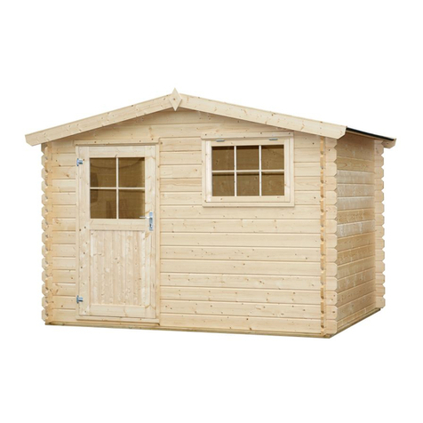
Universo Consumer Products
Universo Consumer Products CA2877 manual
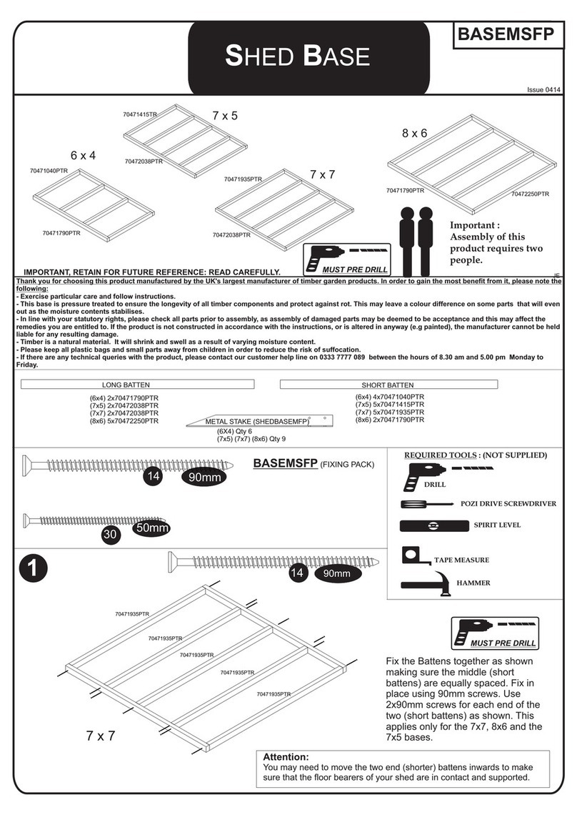
Forest garden
Forest garden BASEMSFP Assembly instructions
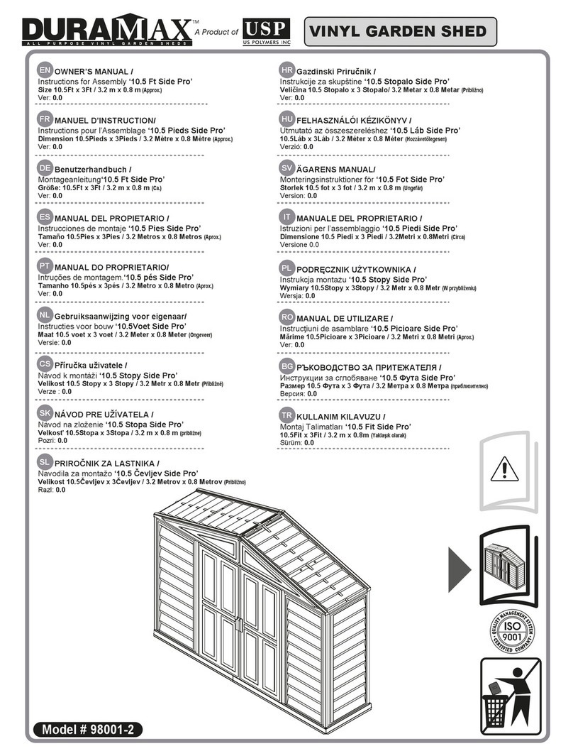
USP
USP Duramax Side Pro 98001-2 owner's manual

finnhaus
finnhaus ELEGANTO 3024 Assembly instructions

Tiger
Tiger RAYNER General assembly instructions

Lemeks
Lemeks Palmako Hanna PA34-3636 Assembly, installation and maintenance manual

DISCOVER
DISCOVER SkyLight Shed manual
Jimmy at work
Jimmy at work SPR10001 owner's manual
Grosfillex
Grosfillex ABRI DECO 11 Assembly instructions

Palmako
Palmako Irene installation manual
Lemeks
Lemeks Palmako Susanna FR44-5332-1 Assembly, installation and maintenance manual

Forest garden
Forest garden APEX PREMIUM Assembly instructions


