Solido Eco User manual

Montageanleitung
DS020642/06.2017
solido 80
Holz
mit Antrieb solido ECO
für ein- und zweiflügelige
Anlagen
solido 80
timber
with drive solido ECO for
single and double leaf doors

2
DS020642/06.2017
SW 10,
13, 17
Allgemeine Informationen
Benötigtes Werkzeug Seite 2
Lieferumfang Seite 3
Montage
Montageschritte ein- und zweiflügelig Seite 4
Schiebetürbeschläge
Solido 80 Holz Seite 7
bis 80 kg Flügelgewicht
Technische Hinweise
Einbauzeichnungen Antrieb solido ECO Seite 8
Montageanleitung Solido ECO Seite 11
General Information
Required tools Page 2
Scope of supply Page 3
Assembly
Mounting steps single and double door Page 4
Sliding door hardware
Solido 80 timber Page 7
up to 80 kg leaf weight
Technical notes
Mounting drawings drive solido EC Page 8
Installation instructions Solido ECO Seite 11
Benötigtes Werkzeug
Required tools
Größe/Size 3,
4 und/and 5
Größe/Size 6
und/and 8
Solido 80 Holz/Solido 80 timber
Inhalt/Content
3
DS020642/06.2017
General Information
Required tools Page 2
Scope of supply Page 3
Assembly
Mounting steps single and double door Page 4
Sliding door hardware
Solido 80 timber Page 7
up to 80 kg leaf weight
Technical notes
Mounting drawings drive solido EC Page 8
Installation instructions Solido ECO Seite 11
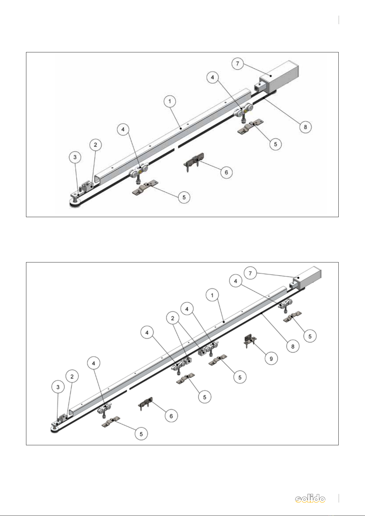
Solido 80 Holz/Solido 80 timber
Lieferumfang/Sope of delivery
1. Laufschiene
2. Stopper
3. Umlenkrolle
4. Rollapparat
5. Flansch
1. Track
2. End Stop
3. Deflection roll
4. Trolley
5. Flange
6. Zahnriemenverbinder
7. elektrischer Antrieb
8. Zahnriemen
6. Toothed belt connector
7. elektrical drive
8. Tooth belt
Abb. 1 einflügelig/ fig. 1 single leaf
Abb. 2 zweiflügelig/ fig. 2 double leaf
1. Laufschiene
2. Stopper
3. Umlenkrolle
4. Rollapparat
5. Flansch
6. Zahnriemenverbinder
1. Track
2. Endstop
3. Deflection roller
4. Trolley
5. Flange
6. Toothed belt connector
7. elektrischer Antrieb
8. Zahnriemen
9. Zahnriemenmitnehmer
7. elektrical drive
8. Tooth belt
9. Tooth belt clamp

4
DS020642/06.2017
1. Laufschiene entsprechend der vorliegenden Befesti-
gung montieren. Die entsprechenden Einbauschnitte
finden Sie auf Seite 7.
1. Mount the track as it is appropriate for the used
mounting parts. The relevant sections can be found
on page 7
2. Rollen, Stopper und Umlenkrolle in die Laufschiene
schieben. Hierbei ist auf die Ausrichtung der Rollap-
parate zu achten (siehe Abb. 3 und Abb. 15).
(Achtung: Bei der zweiflügeligen Ausführung
kommen 2 Stopper in die Mitte.)
2. Push rolls, stops and deflection roll into the track.
While doing this, mind the orientation of the trolley
(see fig. 3 and fig. 15). (Attention: In case of the
double leaf type 2 stops are put in the middle.)
3. Antrieb mit passendem Adapter am Ende der Lauf-
schiene einsetzen und Gewindestift anziehen.
3. Put drive with suitable adapter at the end of the
track and tighten grub screw.
4. Flansche mittig der Flügelstärke auf der Schiebe-
tür befestigen. Die entsprechenden Abstände finden
Sie auf Seite 8 (Abb. 15).
4. Fix flange in the centre of the door gauge on the
sliding door. The relevant clearances can be found on
page 8 (fig. 15).
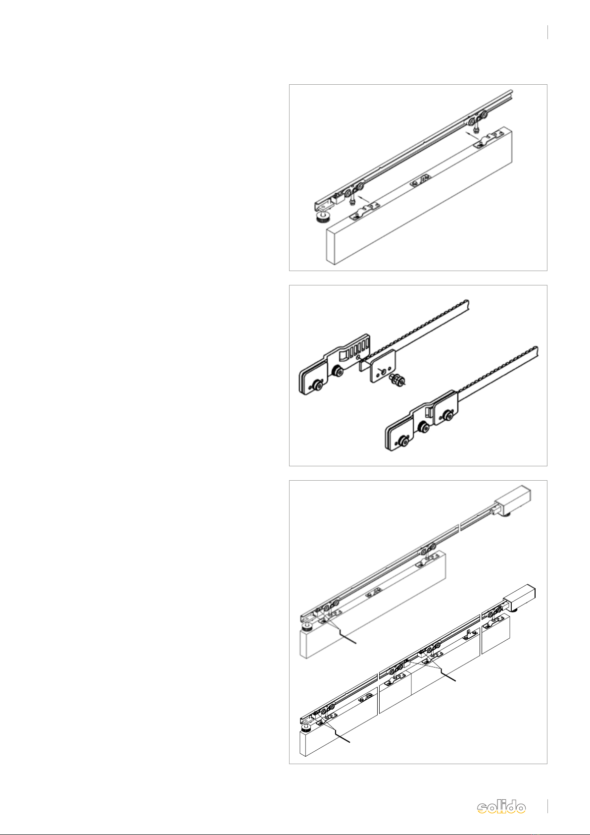
5. Zahnriemenverbinder: Befestigungsplatte vom
Winkel abschrauben. Winkel zwischen den
zwei Flanschen mittig auf der Schiebetür mittels
den beiliegenden Schrauben montieren.
5. Toothed belt connector: Unscrew fixing plate from
bracket. Mount bracket between the two flanges in
the centre on the sliding door using the enclosed
screws.
5a. Zweiflügelige Ausführung:
Mitnehmer: Befestigungsplatte vom Winkel ab-
schrauben. Winkel zwischen den zwei Flanschen
mittig des zweiten Flügels wie in Abb. 6 dargestellt
mittels der beiliegenden Schrauben montieren.
5a. Double leaf type:
Driver: Unscrew fixing plate from bracket. Mount
bracket between the two flanges, as shown in fig. 6,
in the centre on the sliding door using the enclosed
screws.
Abb. 4
Abb. 5
Abb. 3
Abb. 6
Solido 80 Holz/Solido 80 timber
Montageschritte, ein- und zweiflügelig/Mounting steps, single and double leaf
fig. 3
fig. 4
fig. 5
fig. 6
5
DS020642/06.2017
Abb. 7
Abb. 8
Abb. 9
Solido 80 Holz/Solido 80 timber
Montageschritte, ein- und zweiflügelig/Mounting steps, single and double leaf
fig. 7
fig. 9
fig. 8
6. Schiebetür in die Tragschrauben der Rollapparate
einhängen, Höhe (s. Seite 7) einstellen und Konter-
mutter anziehen.
6. Hang sliding door into the holding screws of the
trolley hangers, height (see page 7), set and tighten
counter screw.
7. Ein Ende des Zahnriemens in die Ausnehmung
der Befestigungsplatte einlegen und mit der Platte
klemmen.
7. Put one end of the toothed belt into the cut of the
fixing plate and clamp with the plate.
8. Schiebetür in beide Endstellungen verfahren.
Stopper und Umlenkrolle positionieren und die
Gewindestifte anziehen.
8. Move sliding door into both end positions. Position
stops and deflection roll and tighten grub screws.

6
DS020642/06.2017
Abb. 10
Abb. 11
Abb. 12
9. Zahnriemen um Antriebsritzel und Umlenkrolle
führen und mit Vorspannung in die andere Aus
nehmung der Befestigungsplatte einsetzen und mit
der Platte klemmen.
9. Guide toothed belt around drive pinion and
deflection roll and with pretension, put it into the
other cut of the fixing plate and clamp with plate
10. Befestigungsplatte mit Zahnriemen an dem Befesti-
gungswinkel verschrauben.
10. Befestigungsplatte mit Zahnriemen an dem Befesti-
gungswinkel verschrauben.
10a. Zweiflügelige Ausführung:
Schiebetüren in die geschlossene Endstellung ver-
fahren. Zahnriemen um Antriebsritzel und Umlenk
rolle führen und mit Vorspannung in die andere
Ausnehmung der Befestigungsplatte einsetzen und
mit der Platte klemmen.Befestigungsplatte des
Mitnehmers mit Zahnriemen verbinden und an
dem Befestigungswinkel verschrauben.
10a. Double leaf type:
Move sliding doors into the closed end position.
Guide toothed belt around drive pinion and
deflection roll and with pretension, put it into the
other cuts of the fixing plate and clamp with plate.
Join fixing plate of driver with toothed belt and
screw it on the fixing bracket.
11. Die Umlenkrolle lösen und mit Hilfe eines Schrau-
bendrehers, der zwischen Stopper und Umlenkrolle
angesetzt wird, den Zahnriemen spannen. Der
Zahnriemen sollte sich noch leicht zusammen-
drücken lassen.
11. Loosen deflection roll and tension the toothed belt
by means of a screwdriver that is applied between
stop and deflection roll. It should be possible to
press the toothed belt slightly together.
.
fig. 10
fig. 11
fig. 12
Solido 80 Holz/Solido 80 timber
Montageschritte, ein- und zweiflügelig/Mounting steps, single and double leaf
7
DS020642/06.2017
Abb. 13 Abb. 14
fig. 14
fig. 13
Solido 80 Holz/Solido 80 timber
bis 80 kg Flügelgewicht/up to 80 kg leaf weight
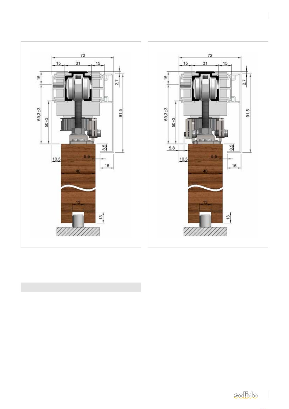
Abb. 13: Solido 80 Holz mit Antrieb solido ECO,
einflügelig bis 80 kg, elektrisch
Fig. 13: Solido 80 timber with drive solido ECO,
single leaf up to 80 kg, electrical
Abb. 14: Solido 80 Holz mit Antrieb solido ECO,
zweiflügelig bis 70 kg, elektrisch
Abb. 14: Solido 80 timber with drive solido ECO,
double leaf up to 70 kg, electrical
Solido 80 Holz mit Elektroantrieb
Solido 80 timber with electrical drive
8
DS020642/06.2017
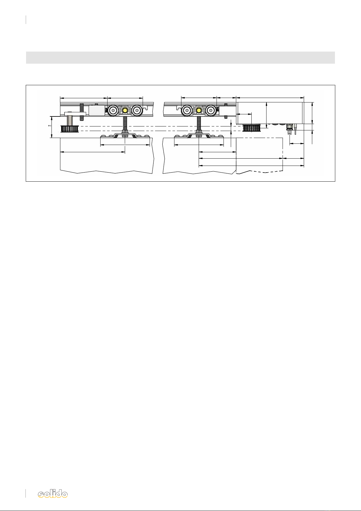
Einbauzeichnung Antrieb solido ECO/Mounting drawing drive solido ECO
solido 80
10
115
151
115
87
195,5 49,5
245
50
~
15
15845,582,8
~
110 82,8
50 3
36
60,5
33,5
Abb. 15
Solido 80 Holz/Solido 80 timber
Antrieb solido ECO/electrical drive solido ECO
fig. 15

DS020642/06.2017
Solido ECO
sliding door drive
Montageanleitung
Installation instructions
Solido ECO
Schiebetürantrieb

10
DS020642/06.2017
1. Eigenschaften des Solido ECO
• Netzanschluss 230V (ca. 2,5 m Kabel)
• geeignet für Dauernetzbetrieb 230V
• Gehäuse (ca. 50 x 50 x 158 mm) mit Motor und
integrierter Steuerung
• integrierte Trennrelais geeignet für lange Steuerleitungen
• geeignet für Bussystem
• extern wird ein nicht verriegelter Serientaster benötigt
oder optional ein Funksender
• alle Motorfunktionen über den nicht verriegelten Serien-
taster einstellbar (z.B. Geschwindigkeitsumschaltung, Push &
Go-Betrieb, automatischer Zulauf usw.)
• Multifunktions-LED zur Statusanzeige
• Reversion bei Auftreffen auf Hindernis in Zu-Richtung
• TÜV-geprüft nach DIN EN 18650-2 Low-Energy
• Wenn kein Serientaster eingebaut wird benötigt man einen
Einstellhilfetaster
Solido ECO
Allgemeine Informationen/General information
1. Properties of the Solido ECO
• power supply 230V (approx. 2.5 m cable)
• suitable for continuous mains operation 230V
• housing (approx. 50 x 50 x 158 mm) with motor and
integrated control
• integrated cut-off relay suitable for long control lines
• suitable for bus system
• externally a non-interlocked two-circuit breaker is required or,
optionally, a wireless transmitter
• all modes of operation of the motor can be set by the non-
interlocked two-circuit breaker (e. g. speed change, Push & Go
operation, automatic closing etc.)
• multi-functional LED for status display
• reversion when an obstacle is detected during closing
• TÜV certified according to DIN EN 18650-2 Low Energy
• If no two-circuit breaker is installed, an
adjustment aid button switch is required

11
DS020642/06.2017
1. Zahnritzel, 24 Zähne
2. LED
3. Verschlusskappe „Lernfahrt“
4. Verschlusskappe „Programmierung“
5. fünfadriges Anschlusskabel
6. Antenne
7. Adapter
Solido ECO
Allgemeine Informationen/General information
Lieferumfang/ Scope of supply
1. pinion, 24-tooth
2. LED
3. cap "teach-in operation"
4. cap "programming"
5. five-core connection cable
6. antenna
7. adapter
Abb. 1
fig. 1

12
DS020642/06.2017
Einstellhilfekabel Elektroantriebe
Kabelfarbe Kabelnummer Bezeichnung
1
2
3
4
blau
braun
schwarz
grau
0 V
230 V
AUF
ZU
grün/gelb Schutzleitergrün/gelb
Einstellhilfekabel Elektroantriebe
Kabelfarbe Kabelnummer Bezeichnung
1
2
3
4
blau
braun
schwarz
grau
0 V
230 V
AUF
ZU
grün/gelb Schutzleitergrün/gelb
Einstellhilfekabel Elektroantriebe
Kabelfarbe Kabelnummer Bezeichnung
1
2
3
4
blau
braun
schwarz
grau
0 V
230 V
AUF
ZU
grün/gelb Schutzleitergrün/gelb
Einstellhilfekabel Elektroantriebe
Kabelfarbe Kabelnummer Bezeichnung
1
2
3
4
blau
braun
schwarz
grau
0 V
230 V
AUF
ZU
grün/gelb Schutzleitergrün/gelb
Titel: SBL23DN/10VA Revision: 1.4 Seiten 1/1
Stand Revision: 30.11.2011 Sonstiges:
Motordaten SBL23DN/10VA
Achtung! Info für Bussystem!
SBL23DN - jeder Motor in einem Bussystem muss jeweils mit einem Aktor versehen werden.
Keine Parallelschaltung von mehreren Motoren auf einem Aktor!
Sonderverdrahtung nur nach Rücksprache mit dem Hersteller und gesonderter Freigabe!
SBL23DN/H (horizontal)
Zuleitung 230 V / 50 Hz
Standby ca. 1,8 W
Leistung P. max. ca. 10 W
Netzteil intern 12 V / 10 VA
Gehäuse eloxiert ca. 50 x 50 x 160 mm
Schutzart IP54
Konformität CE
Schutzklasse I
Umgebungstemperatur -20°C bis +70°C
Anschlusskabel ca. 3,0 m (horizontal oder vertikal)
Laufzeit Timeout / Lernfahrt ca. 270 sec.
Laufzeit Timeout / Normalbetrieb ca. 120 sec.
Abtriebswelle Ø 6 x 12 mm rostfreier Stahl
Radialkraft an der Mitte Motorachse max. 50 N (bei 6 mm)
Dauer Drehmoment 0,3 Nm 100 % ED
Kurzzeitig zulässiges Drehmoment 0,9 Nm < 1 sec.
Krafterkennung internes Drehzahl Messsystem (Tacho)
SBL23DN/V (vertikal)
Motor 230 V / 50 Hz
Zahnriemen Kabel vertikal
Laufschiene
5
M
1 ~
Motor 230 V / 50 Hz
Zahnriemen
Kabel horizontal
Laufschiene M
1 ~
5
Rollladentaster oder
Serientaster/230 V AC min. 8 A
PE
N
L1
Zuleitung 230 V / 50 Hz
Bauseitige Absicherung
gemäß VDE erforderlich!!!
Taster
Auf Zu
Grün/Gelb
Blau
Braun
Grau
Schwarz
M
1 ~
icp
1
2
4
3
nicht verriegelter
Serientaster/230 V AC min. 8 A
Solido ECO
Allgemeine Informationen & Inbetriebnahme/General Information & Set-up
2.1 Anschluss/Connection
Einstellhilfekabel
Der Motor verfügt über ein 5-poliges 2,5 m langes, nummeriertes, halogenfreies Anschlusskabel:
The motor has a 5-pole 2.5 m long, numbered, halogen-free connection cable: green/yellow = protective
grün/gelb = Schutzerde
1 = Null
2 = L1 (Dauerphase)
3 = „Auf“
4 = „Zu“
Nach Anschluss der 230V Versorgungsspannung sowie der Schutzerde, schließen Sie das Kabel 3an die „Auf“-Taste und das Kabel
4an die „Zu“-Taste Ihres nicht verriegelten Serientasters an.
After connecting the 230V supply voltage as well as the protective earth, connect the cable 3 to the “open” button
and the cable 4 to the “close” button of your non-interlocked circuit breaker.
ACHTUNG!
Soll im späteren Betrieb kein Serientaster verwendet werden, nehmen Sie die folgenden Einstellungen
mit Hilfe des Einstellhilfetasters (Art.-Nr. 102246122) vor. Spätere Umprogrammierungen sind dann nur nach erneutem
Anschluss des Einstellhilfetasters möglich.
Berücksichtigen Sie dies bitte bei der Montage und Zugänglichkeit ihres Anschlusspunktes (z.B. Verteilerdose).
ATTENTION!
If no two-circuit breaker is to be used for later operation, please make the following settings with the help of the
adjustment aid button (art.-no. 102246122). Later reprogramming is only possible in that case if the adjustment aid
button is reconnected.
Consider this with regard to mounting and accessibility of your connection point (e. g. joint box) please.
geen/yellow = earth
1 = null
2 = L1 (permanent phase)
3 = „open“
4 = „close“
geen/yellow
Not locked serial button/230 V AV min. 8 A
feed line 230 V/50 Hz,
protection by customer
according to VDE

13
DS020642/06.2017
Solido ECO
Allgemeine Informationen & Inbetriebnahme/General Information & Set-up
2.2 Inbetriebnahme/Set-up
Wichtig:
• An der Unterseite des Solido ECO befinden sich zwei Verschlusskappen (siehe S. 11, Abb. 1)
• Öffnen Sie die Verschlusskappe „Programmierung“ (Abb. 1, Pos. 4) und schieben Sie den darunter liegenden
Schalter in Richtung Anschlusskabel. Der Antrieb befindet sich nun im Programmiermodus. Eine Programmierung
bzw. Einstellung des Antriebes ist nur in dieser Stellung möglich.
• Zum Testen der vorgenommenen Programmierung, sowie im Normalbetrieb, muss der Schalter wieder Richtung
Antriebsritzel in die Normalstellung zurückgeschoben werden.
Important:
• At the bottom of the Solido ECO there are two caps (see p. 13, fig. 1)
• Open the cap "programming" (fig. 1, item 4) and push the subjacent switch in the direction of the connection cable.
The drive is now in programming mode. Programming or setting the drive is only possible in this position.
• For test driving the completed programming, as well as in normal operation, the switch has to be pushed back in the
direction
of the drive pinion into the normal position.
2.2.1 Lernfahrt durchführen/ Carry out teach-in operation
Hinweis:
Vor dem Start der Lernfahrt sollte sich die Tür in einer halbgeöffneten Stellung befinden.
Gehen Sie bitte wie folgt vor:
• Öffnen Sie die Verschlusskappe „Lernfahrt“ (Abb. 1, Pos. 3)
• Betätigen Sie nun den gelben Knopf um die Lernfahrt zu starten
Note:
Before starting the teach-in operation, the door should be half open.
Proceed as follows please:
• Open the cap "teach-in operation" (fig. 1, item 3)
• Push the yellow button to start the teach-in operation.
Hinweis:
Während der gesamten Lernfahrt leuchtet die Kontroll-LED (Abb. 1, Pos. 2) gelb.
Die Tür bewegt sich zunächst in eine Richtung bis zur Endlage. Danach fährt die Schiebetür bis zur anderen Endlage.
Der Vorgang wird am Ende, bei erfolgreichem Abschluss, durch zwei kurze Signaltöne quittiert.
Sollte dies nicht der Fall sein, führen Sie den Vorgang bitte erneut durch.
Nach erfolgreichem Abschluss der Lernfahrt, kann die Verschlusskappe „Lernfahrt“ wieder montiert werden.
Note:
During the entire teach-in operation, the control LED (fig. 1, item 2) is lit yellow.
The door first moves in one direction to the end position. Then the sliding door moves to the other end position.
The operation is acknowledged at the end - in case of successful conclusion - by two short blips. If this is not the case,
please repeat the operation.
After the successful conclusion of the teach-in operation, the cap "teach-in operation" can be put on again.

14
DS020642/06.2017
3. Einstellungsebenen/Adjustment planes
Der Solido ECO verfügt über 4 Einstellungsebenen.
Ebene 1: Einstellung von:
1. Laufrichtung
2. Dauer- oder Impulsbetrieb
Ebene 2: Einstellung von:
1. Push & Go- Funktion
2. automatischer Zulauf
Ebene 3: Einstellung von:
1. Geschwindigkeit
2. Offenhaltezeit bei automatischem Zulauf
Ebene 4: Einstellung von:
1. Länge der Brems- und Startrampen
3.1 Ebene 1/Plane 1
3.1.1 Laufrichtung/Direction of travel:
Bei korrekt eingestellter Drehrichtung leuchtet die LED am Antrieb bei der „Auf“-fahrt grün und bei einer „Zu“-fahrt
rot. Wenn dies nicht der Fall ist, muss die Motorlaufrichtung geändert werden. Dazu gehen Sie wie folgt vor:
• Drücken und halten Sie die Auf- und Zu-Taste Ihres nicht verriegelten Serien- oder Einstellhilfetasters zeitgleich für
ca. 3 Sek. bis ein kurzer Signalton ertönt und ein einmaliges Aufleuchten der LED erfolgt.
• Lassen sie beide Tasten los.
• Wählen Sie nun direkt durch kurzes Drücken der Auf-Taste Ihre gewünschte Einstellung:
2 x Auf-Taste = Änderung der Laufrichtung (Quittierung durch 2 x Signalton und 2 x LED-Aufleuchten)
1 x Auf-Taste = Rückkehr zur Werkseinstellung (Quittierung durch 1 x Signalton und 1 x LED-Aufleuchten)
If the sense of rotation has been set correctly, the LED on the drive is lit green during opening and red during closing. If
this is not the case, the sense of rotation of the motor has to be changed. For this proceed as follows:
• Press and hold the open and close button of your non-interlocked two-circuit breaker or adjustment aid button
simultaneously for approx. 3 seconds until you hear a short blip and the LED is lit once.
• Release both buttons.
• Choose directly the required setting by briefly pressing the open button:
2 x open button = change of the direction of travel (acknowledged by 2 x blip and 2 x LED light up) 1 x open button =
return to default setting (acknowledged by 1 x blip and 1 x LED light up)
3.1.2 Dauer- oder Impulsbetrieb/Continuous running or pulse operation:
Bei der Ansteuerung des Antriebes kann zwischen Dauer- und Impulsbetrieb gewählt werden. Im Dauerbetrieb fährt die
Tür nur dann, wenn eine Taste gedrückt und festgehalten wird (dauerhaft anliegendes Signal). Wird die Taste losgelas-
sen, bleibt die Tür stehen. Im Impulsbetrieb fährt die Tür bei Betätigen einer Taste los. Zum Stoppen der Tür muss ein
entgegengesetzter Befehl gegeben werden.
For controlling the drive you can choose between continuous running and pulse operation. In case of continuous
running operation, the door only moves when a button is pressed and held (continuously applied signal). When the
button is released, the door comes to a standstill. In case of pulse operation, the door starts moving when a button is
pushed. For stopping the door a reversing order has to be given.
The Solido ECO has 4 adjustment planes.
Plane 1: Setting of:
1. direction of travel
2. continuous running or pulse
operation
Plane 2: Setting of:
1. Push & Go mode
2. automatic closing
Plane 3: Setting of:
1. speed
2. hold-open time in case of
automatic closing
Plane 4: Setting of:
1. lengths of brake and start
ramps
Solido ECO
Allgemeine Informationen & Inbetriebnahme/General Information & Set-up

15
DS020642/06.2017
3.2 Ebene 2/Plane 2
3.2.1 Push & Go - Funktion/Push & Go mode:
Bei aktivierter Push & Go Funktion fährt die Tür, durch leichtes Anstoßen in die gewünschte Richtung, automatisch bis
in die Endlage.
In case of activated Push & Go mode the door moves automatically, by pushing it gently in the desired direction,
into the end position.
Zur Aktivierung gehen Sie wie folgt vor/For activation proceed as follows:
• Drücken und halten Sie die Auf- und Zu-Taste Ihres nicht verriegelten Serien- oder Einstellhilfetasters zeitgleich für
ca. 3 Sek. bis ein kurzer Signalton ertönt und ein einmaliges Aufleuchten der LED erfolgt.
• Lassen sie beide Tasten kurz los.
• Drücken und halten Sie erneut die Auf- und Zu- Taste zeitgleich für ca. 3 Sek. bis zwei kurze Signaltöne ertönen und
ein zweimaliges Aufleuchten der LED erfolgt.
• Lassen sie beide Tasten kurz los.
• Wählen Sie nun direkt durch kurzes Drücken der Auf-Taste Ihre gewünschte Einstellung:
• Press and hold the open and close button of your non-interlocked two-circuit breaker or adjustment aid button
simultaneously for approx. 3 seconds until you hear a short blip and the LED is lit once.
• Release both buttons briefly.
• Press and hold the open and close button simultaneously again for approx. 3 seconds until you hear two short blips
and the LED is lit twice.
• Release both buttons briefly.
• Choose directly the required setting by briefly pressing the open button:
2 x Auf-Taste = Aktivierung der Push & Go - Funktion (Quittierung durch 2 x Signalton und 2 x LED-Aufleuchten)
2 x open button = activation of the Push & Go mode (acknowledged by 2 x blip and 2 x LED light up)
1 x Auf-Taste = Deaktivierung der Push & Go - Funktion (Werkseinstellung)
(Quittierung durch 1 x Signalton und 1 x LED-Aufleuchten)
1 x open button = deactivation of the Push & Go mode (default setting)
(acknowledged by 1 x blip and 1 x LED lighting up)
Zur Einstellung der Betriebsart gehen Sie wie folgt vor/ For setting the mode of operation proceed as follows:
• Drücken und halten Sie die Auf- und Zu -Taste Ihres nicht verriegelten Serien - oder Einstellhilfetasters zeitgleich für
ca. 3 Sek. bis ein kurzer Signalton ertönt und ein einmaliges Aufleuchten der LED erfolgt.
• Lassen sie beide Tasten kurz los.
• Wählen Sie nun direkt durch kurzes Drücken der ZU-Taste Ihre gewünschte Einstellung:
• Press and hold the open and close button of your non-interlocked two-circuit breaker or adjustment aid button simulta
neously for approx. 3 seconds until you hear a short blip and the LED is lit once.
• Release both buttons briefly.
• Choose directly the required setting by briefly pressing the CLOSE button:
2 x Zu-Taste = Dauerbetrieb (Totmannbetrieb) (Quittierung durch 2 x Signalton und 2 x LED-Aufleuchten)
2 x close button = continuous running (dead-man mode) (acknowledged by 2 x blip and 2 x LED light up)
1 x Zu-Taste = Impulsbetrieb (Werkseinstellung) (Quittierung durch 1 x Signalton und 1 x LED-Aufleuchten)
1 x close button = pulse operation (default setting) (acknowledged by 1 x blip and 1 x LED light up)
Solido ECO
Allgemeine Informationen & Inbetriebnahme/General Information & Set-up

16
DS020642/06.2017
3.3.1 Geschwindigkeit/Speed:
Der Antrieb verfügt über drei einstellbare Geschwindigkeiten. Durch Abnahme des Antriebes nach DIN EN 18650-2
Low-Energy ergibt sich die zu wählende Geschwindigkeit aus der angehängten Tabelle (A1, Seite 27).
The drive has three adjustable speeds: Due to the certification of the drive according to DIN EN 18650-2
Low Energy, the speed is to be chosen by using the attached table (A1, page 27).
Zur Einstellung gehen Sie wie folgt vor/For setting proceed as follows::
• Drücken und halten Sie die Auf- und Zu-Taste Ihres nicht verriegelten Serien- oder Einstellhilfetasters zeitgleich für
ca. 3 Sek. bis ein kurzer Signalton ertönt und ein einmaliges Aufleuchten der LED erfolgt.
• Lassen sie beide Tasten kurz los.
• Drücken und halten Sie erneut die Auf- und Zu- Taste zeitgleich für ca. 3 Sek. bis zwei kurze Signaltöne ertönen
und ein zweimaliges Aufleuchten der LED erfolgt.
• Lassen sie beide Tasten kurz los.
• Drücken und halten Sie erneut die Auf- und Zu- Taste zeitgleich für ca. 3 Sek. bis drei kurze Signaltöne ertönen
und ein dreimaliges Aufleuchten der LED erfolgt.
• Lassen sie beide Tasten kurz los.
• Wählen Sie nun direkt durch kurzes Drücken der AUF-Taste Ihre gewünschte Einstellung:
3.3 Ebene 3/Plane 3
3.2.2 Automatischer Zulauf/Automatic closing
Bei aktiviertem automatischem Zulauf fährt die Tür, nach Erreichen der Endlage in Auf-Richtung, nach eingestellter
Offenhaltezeit (Ebene 3 Punkt 3.3.2 ) automatisch zu.
When the automatic closing mode is activated (plane 3 item 3.3.2), the door closes automatically, after reaching the
end position of the opening movement, after the pre-set hold-open time.
Zur Aktivierung gehen Sie wie folgt vor/For activation proceed as follows:
• Drücken und halten Sie die Auf- und Zu-Taste Ihres nicht verriegelten Serien- oder Einstellhilfetasters zeitgleich für
ca. 3 Sek. bis ein kurzer Signalton ertönt und ein einmaliges Aufleuchten der LED erfolgt.
• Lassen sie beide Tasten kurz los.
• Drücken und halten Sie erneut die Auf- und Zu- Taste zeitgleich für ca. 3 Sek. bis zwei kurze Signaltöne ertönen
und ein zweimaliges Aufleuchten der LED erfolgt.
• Lassen sie beide Tasten kurz los.
• Wählen Sie nun direkt durch kurzes Drücken der ZU-Taste Ihre gewünschte Einstellung:
• Press and hold the open and close button of your non-interlocked two-circuit breaker or adjustment aid button
simultaneously for approx. 3 seconds until you hear a short blip and the LED is lit once.
• Release both buttons briefly.
• Press and hold the open and close button simultaneously again for approx. 3 seconds until you hear two short blips.
and the LED is lit twice.
• Release both buttons briefly.
• Choose directly the required setting by briefly pressing the CLOSE button:
2 x Zu-Taste = Aktivierung des automatischen Zulaufs (Quittierung durch 2 x Signalton und 2 x LED-Aufleuchten)
2 x close button = activation of the automatic closing mode (acknowledged by 2 x blip and 2 x LED lighting up
1 x Zu-Taste = Deaktivierung des automatischen Zulaufs (Werkseinstellung)
(Quittierung durch 1 x Signalton und 1 x LED-Aufleuchten)
1 x close button = deactivation of the automatic closing mode (default setting)
(acknowledged by 1 x blip and 1 x LED lighting up)
Solido ECO
Allgemeine Informationen & Inbetriebnahme/General Information & Set-up

17
DS020642/06.2017
3.3 Ebene 3/Plane 3
3.3.2 Offenhaltezeit/Hold-open time:
Bei aktiviertem automatischem Zulauf (Ebene 2 Punkt 3.2.2) fährt die Tür, nach Erreichen der Endlage in Auf-Richtung,
nach eingestellter Offenhaltezeit automatisch zu.
When the automatic closing mode is activated (plane 2 item 3.2.2), the door closes automatically, after reaching the
end position of the opening movement, after the pre-set hold-open time.
Zur Einstellung der Offenhaltezeit gehen Sie wie folgt vor/ For setting the hold-open time proceed as follows:
• Drücken und halten Sie die Auf- und Zu-Taste Ihres nicht verriegelten Serien- oder Einstellhilfetasters zeitgleich für
ca. 3 Sek. bis ein kurzer Signalton ertönt und ein einmaliges Aufleuchten der LED erfolgt.
• Lassen sie beide Tasten kurz los.
• Drücken und halten Sie erneut die Auf- und Zu- Taste zeitgleich für ca. 3 Sek. bis zwei kurze Signaltöne ertönen und
ein zweimaliges Aufleuchten der LED erfolgt.
• Lassen sie beide Tasten kurz los.
• Drücken und halten Sie erneut die Auf- und Zu- Taste zeitgleich für ca. 3 Sek. bis drei kurze Signaltöne ertönen und
ein dreimaliges Aufleuchten der LED erfolgt.
• Lassen sie beide Tasten kurz los.
• Wählen Sie nun direkt durch kurzes Drücken der ZU-Taste Ihre gewünschte Einstellung:
• Press and hold the open and close button of your non-interlocked two-circuit breaker or adjustment aid button
simultaneously for approx. 3 seconds until you hear a short blip and the LED is lit once.
• Release both buttons briefly.
• Press and hold the open and close button simultaneously again for approx. 3 seconds until you hear two short blips
and the LED is lit twice.
• Press and hold the open and close button of your non-interlocked two-circuit breaker or adjustment aid button
simultaneously for approx. 3 seconds until you hear a short blip and the LED is lit once.
• Release both buttons briefly.
• Press and hold the open and close button simultaneously again for approx. 3 seconds until you hear two short blips.
and the LED is lit twice.
• Release both buttons briefly.
• Press and hold the open and close button simultaneously again for approx. 3 seconds until you hear three short blips.
and the LED is lit three times.
• Release both buttons briefly.
• Choose directly the required setting by briefly pressing the OPEN button:
1 x Auf-Taste = 10 cm/s (24er- Ritzel)
(Quittierung durch 1 x Signalton und 1 x LED-Aufleuchten)
1 x open button = 10 cm/s (24-tooth pinion)
(acknowledged by 1 x blip and 1 x LED lighting up)
2 x Auf-Taste = 15 cm/s (24er- Ritzel)
(Quittierung durch 2 x Signalton und 2 x LED-Aufleuchten)
2 x open button = 15 cm/s (24-tooth pinion)
(acknowledged by 2 x blip and 2 x LED lighting up)
3 x Auf-Taste = 20 cm/s (24er- Ritzel) (Werkseinstellung)
(Quittierung durch 3 x Signalton und 3 x LED-Aufleuchten)
3 x open button = 20 cm/s (24-tooth pinion) (default setting)
(acknowledged by 3 x blip and 3 x LED lighting up)
Solido ECO
Allgemeine Informationen & Inbetriebnahme/General Information & Set-up

18
DS020642/06.2017
1 x Zu-Taste = 3 Sekunden (Werkseinstellung)
(Quittierung durch 1 x Signalton und 1 x LED-Aufleuchten)
1 x close button = 3 seconds (default setting)
(acknowledged by 1 x blip and 1 x LED lighting up)
2 x Zu-Taste = 20 Sekunden
(Quittierung durch 2 x Signalton und 2 x LED-Aufleuchten)
2 x close button = 20 seconds
(acknowledged by 2 x blip and 2 x LED lighting up)
3 x Zu-Taste = 60 Sekunden
(Quittierung durch 3 x Signalton und 3 x LED-Aufleuchten)
3 x close button = 60 seconds
(acknowledged by 3 x blip and 3 x LED lighting up)
• Release both buttons briefly.
• Press and hold the open and close button simultaneously again for approx. 3 seconds until you hear three short blips
and the LED is lit three times.
• Release both buttons briefly.
• Choose directly the required setting by briefly pressing the CLOSE button:
3.4.1 Länge der Brems- und Startrampen/Length of brake and start ramps:
Der Antrieb verfügt über drei definierte Längen der Brems- und Startrampen.
The drive has three defined lengths of brake and start ramps
kurze Rampe: Türgewicht bis max. 50 kg
mittlere Rampe: Türgewichte bis max. 90 kg
lange Rampe: Türgewichte bis max. 150 kg
Achtung/Attention:
Bei Nichtbeachtung der oben genannten Grenzen, kann es zu mechanischen Schäden am Antrieb kommen.
If the above-mentioned limits are not observed, mechanical damage on the drive can occur.
Zur Einstellung gehen Sie wie folgt vor/For setting proceed as follows:
• Drücken und halten Sie die Auf- und Zu-Taste Ihres nicht verriegelten Serien- oder Einstellhilfetasters zeitgleich für
ca. 3 Sek. bis ein kurzer Signalton ertönt und ein einmaliges Aufleuchten der LED erfolgt.
• Lassen sie beide Tasten kurz los.
• Drücken und halten Sie erneut die Auf- und Zu- Taste zeitgleich für ca. 3 Sek. bis zwei kurze Signaltöne ertönen
und ein zweimaliges Aufleuchten der LED erfolgt.
• Lassen sie beide Tasten kurz los.
• Drücken und halten Sie erneut die Auf- und Zu- Taste zeitgleich für ca. 3 Sek. bis drei kurze Signaltöne ertönen und
ein dreimaliges Aufleuchten der LED erfolgt.
• Lassen sie beide Tasten kurz los.
• Drücken und halten Sie erneut die Auf- und Zu- Taste zeitgleich für ca. 3 Sek. bis vier kurze Signaltöne ertönen und
ein viermaliges Aufleuchten der LED erfolgt.
• Lassen sie beide Tasten kurz los.
• Wählen Sie nun direkt durch kurzes Drücken der AUF-Taste Ihre gewünschte Einstellung:
• Press and hold the open and close button of your non-interlocked two-circuit breaker or adjustment aid button
simultaneously for approx. 3 seconds until you hear a short blip and the LED is lit once.
3.4 Ebene 4/Plane 4
short ramp: door weight up to max. 50 kg
medium ramp: door weight up to max. 90 kg
long ramp: door weight up to max. 150 kg
Solido ECO
Allgemeine Informationen & Inbetriebnahme/General Information & Set-up

19
DS020642/06.2017
• Release both buttons briefly.
• Press and hold the open and close button simultaneously again for approx. 3 seconds until you hear two short blips.
and the LED is lit twice.
• Release both buttons briefly.
• Press and hold the open and close button simultaneously again for approx. 3 seconds until you hear three short blips
and the LED is lit three times.
• Release both buttons briefly.
• Press and hold the open and close button simultaneously again for approx. 3 seconds until you hear four short blips
and the LED is lit four times.
• Release both buttons briefly.
• Choose directly the required setting by briefly pressing the OPEN button:
1 x Auf-Taste = kurze Rampe
(Quittierung durch 1 x Signalton und 1 x LED-Aufleuchten)
1 x open button = short ramp
(acknowledged by 1 x blip and 1 x LED lighting up)
2 x Auf-Taste = mittlere Rampe
(Quittierung durch 2 x Signalton und 2 x LED-Aufleuchten)
2 x open button = medium ramp
(acknowledged by 2 x blip and 2 x LED lighting up)
3 x Auf-Taste = lange Rampe (Werkseinstellung)
(Quittierung durch 3 x Signalton und 3 x LED-Aufleuchten)
3 x open button = long ramp (default setting)
(acknowledged by 3 x blip and 3 x LED lighting up)
Hinweis/Note:
Zum Testen der vorgenommenen Programmierung, sowie im Normalbetrieb, muss der Schalter wieder Richtung
Antriebsritzel in die Normalstellung zurückgeschoben werden.
For test driving the completed programming, as well as in normal operation, the switch has to be pushed back in the direction of
the drive pinion into the normal position.
Solido ECO
Allgemeine Informationen & Inbetriebnahme/General Information & Set-up

20
DS020642/06.2017
Gehen Sie wie folgt vor/Proceed as follows:
• Unterbrechen Sie die Stromzufuhr zum Solido ECO für ca. 10 Sek.
• Sobald die Stromzufuhr wiederhergestellt ist, drücken und halten Sie innerhalb von 60 Sek. die PROG-Taste am
neu einzulernenden Sender aus ca. 1 m Entfernung und nähern sich dem Antrieb, bis ein kurzer Signalton und ein
Aufleuchten der LED die Verbindung bestätigt (Abstand < ca. 40 cm).
• Drücken Sie innerhalb von ca. 2 Sek. die AUF-Taste am neu einzulernenden Sender; ein kurzer Signalton (ca.1 Sek.)
und ein Aufleuchten der LED bestätigen die korrekte Programmierung. Taste loslassen.
• Interrupt the power supply to the Solido ECO for approx. 10 seconds.
• As soon as the power supply is restored, press and hold the PROG button on the transmitter to be taught in within
60 seconds from a distance of approx. 1 m and get closer to the drive until you hear a short blip and the LED is lit to
acknowledge the connection (distance < approx. 40 cm).
• Press the OPEN button on the transmitter to be taught in within approx. 2 seconds; a short blip (approx. 1 second)
and the LED lighting up acknowledge the correct programming. Release button.
Der Sender ist nun als Mastersender programmiert. Für den Fall, dass der Mastersender verloren geht, oder ein anderer
Mastersender erwünscht ist, muss ein neuer Sender als Master eingelernt werden.
Jeder Sender des Herstellers kann als Mastersender durch die oben genannte Prozedur eingelernt werden.
Der aktuelle Mastersender wird hierdurch ersetzt.
The transmitter is now programmed as master transmitter. In case that the master transmitter gets lost or another
master transmitter is required, a new transmitter has to be taught in as master.
Any transmitter of the manufacturer can be taught in as master transmitter in the above-mentioned manner. The
current master transmitter will thus be replaced.
4. Einlernen eines Senders (Funk)/Teach-in of a transmitter (wireless)
Funkhandsender/Wireless hand-held transmitter
Wandsender/wall-mounted transmitter
Prog. T4/ Prog. T4
Schraube/Screw
Typenschild außen/nameplate outside
Prog.-Taste T3/ Prog button T3
Solido ECO
Allgemeine Informationen & Inbetriebnahme/General Information & Set-up
This manual suits for next models
1
Table of contents
Popular Door Opening System manuals by other brands

Dormakaba
Dormakaba ED 100 LE installation instructions

cinetto
cinetto LIBRO MAXI PS11 Assembly instructions

Falcon
Falcon SC 60 Series Installation instruction

Assa Abloy
Assa Abloy Yale 1105 installation instructions

Automatic Technology
Automatic Technology GDO-12Hir Quick operation guide

Rutland
Rutland ITS.11204 manual


