LCN 1261 CUSH User manual

*29809*
29809
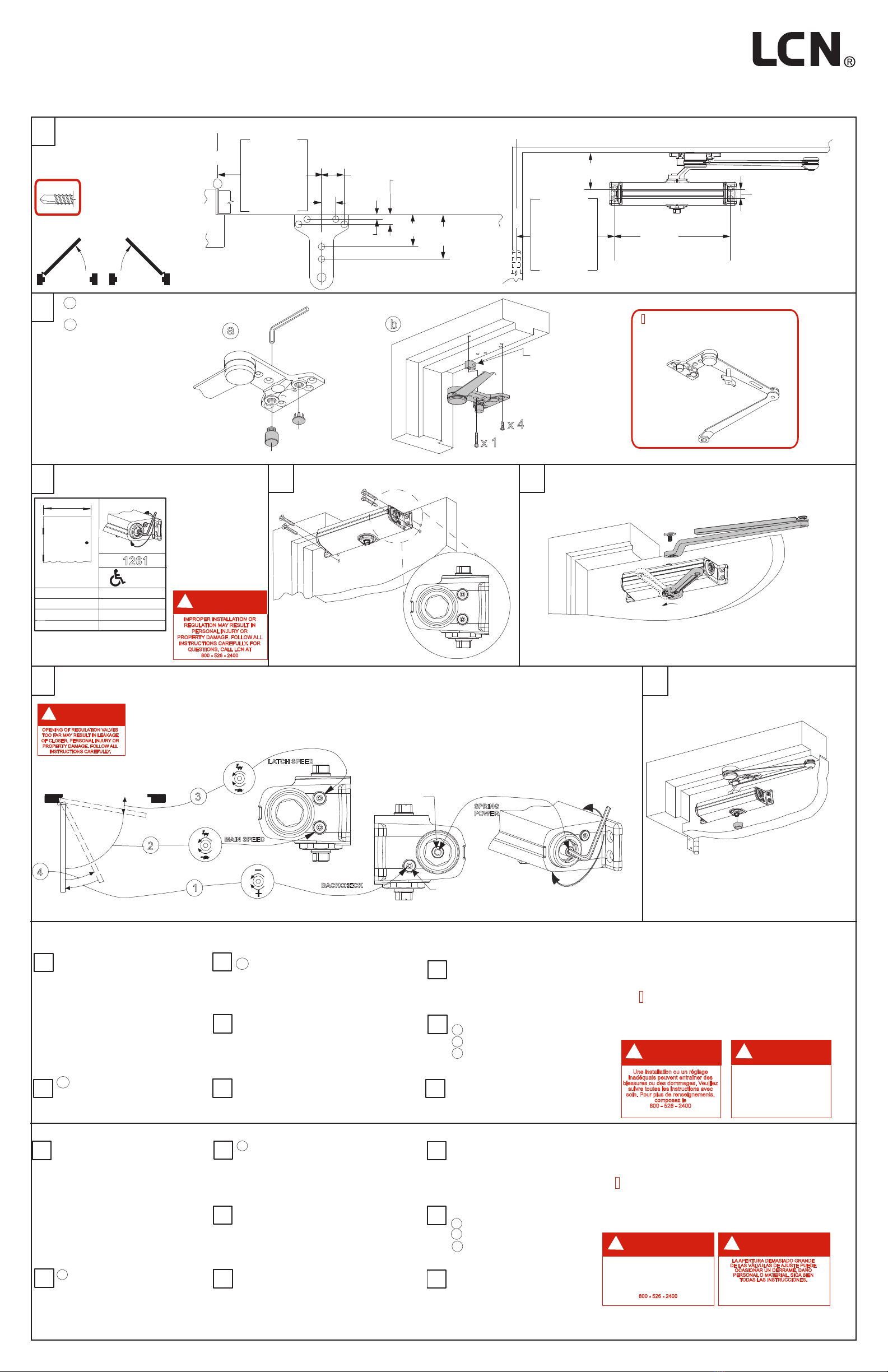
85°- 90°- 100° - 110° Template
Push Side Mounting
1261 CUSH
Installation Instructions
1261 Instructions Cush et gabarit de 85°-90°-100°-110° pour une installation sur le côté à pousser.
6
7
NOTE: la fermeture d'une porte ouverte à 90°
prend normalement de 5 à 7 secondes, ce
délai est réparti entre la vitesse de fermeture
et la vitesse de verrouillage.
I
3
5
2
1
4
Mesurez la largeur de la porte.
Réglez le ressort selon les
indications du tableau
6
2
1
7
Determine la anchura de la puerta.
Ajuste la fuerza del resorte según
lo indicado en el gráfico.
NOTA: El tiempo de cerrado "Normal" de una
puerta abierta a 90° es de 5 hasta 7 segundos,
dividido igualmente entre la velocidad principal
y la velocidad de seguro.
BRAZO DE RETENCIÓN: Para
embragar o desembragar la
característica de retención, dar un
cuarto de vuelta (1/4) al cabo.
I
BRAS DE RETENUE: Pour engager ou
désengager le mécanisme de retenue,
tournez la manette de contrôle d'un
quart (1/4) de tour.
a La main de la console
doit être adaptée à celle de
la porte avant l'installion.
b Ouvrez la porte à environ
45°, fixez le bras au cadre à
l'aide des attaches fournies.
5
4
a Debe de hacerse coincidir el
lado de la zapata con la puerta
antes de montarla.
UNA INSTALACIÓN O UN AJUSTE
INCORRECTOS PUEDEN RESULTAR
EN DAÑO PERSONAL O MATERIAL.
SIGA BIEN TODAS LAS INSTRUCCIONES.
PARA MÁS INFORMACIONES,
LLAMA A LCN AL
800 - 526 - 2400
ADVERTENCIA
!
LA APERTURA DEMASIADO GRANDE
DE LAS VÁLVULAS DE AJUSTE PUEDE
OCASIONAR UN DERRAME, DAÑO
PERSONAL O MATERIAL. SIGA BIEN
TODAS LAS INSTRUCCIONES.
ADVERTENCIA
!
DANGER
!
UNE OUVERTURE EXAGÉRÉE DES
SOUPAPES DE RÉGLAGE PEUT
ENTRAÎNER DES FUITES, DES
BLESSURES OU DES DOMMAGES.
VEUILLEZ SUIVRE LES INSTRUCTIONS
AVEC SOIN.
Une installation ou un réglage
inadéquats peuvent entraîner des
blessures ou des dommages. Veuillez
suivre toutes les instructions avec
soin. Pour plus de renseignements,
composez le
800 - 526 - 2400
DANGER
!
1261 Instrucciones CUSH para plantilla 85°-90°-100°-110° con montaje del lado del empuje.
Press cap onto shaft.
7
Sujeta el cerrador a la puerta
con los tornillos ya incluidos.
Fixez le ferme-porte sur
la porteavec les attaches
fournies.
3
Localice la plantilla apropiada.
Marque el centro de todos los
agujeros. Barrene
agujeros de 5/32".
Repérez le gabarit approprié.
Marquez le centre de tous les
trous. Percezdes trous
de 5/32 po.
a Shoe must be "handed"
to match door before mounting.
b Open door to approx. 45°,
attach arm to frame
with fasteners provided.
2
2
3
3/16
1
11/16
81 mm
43 mm
1
1/16
27 mm
5/16
8 mm
10 1/4
260 mm
11 3/8
283 mm
12
305 mm
= 85°
= 90°
= 100°
C
L
2
3/8
60 mm
11/16
17 mm
1
Note: Steps 1-7 show left hand door mount, right hand door is opposite.
Locate proper template. Center punch all hole locations. For self reaming tapping
screws (SRT) drill 1/8"
pilot holes.
SRT Screw
LH
RH
Reduce installation torque
if using SRT screws in
wood. The use of wood
screws is recommended
for wood.
* Locate closer & shoe from
centerline of pivot or swing
clear hinges when used.
=
37 N-m
28 ft/lbs
MAXIMUM
OPENING
TORQUE
=
37 N-m
28 ft/lbs
MAXIMUM
OPENING
TORQUE
x 4
x 1
b
Fifth hole spacer
Espaceur du
cinquième trou
Espaciador para
el quinto agujero
a
2
I
HOLD OPEN ARM: To engage
or disengage hold open feature,
turn control handle one-quarter
(1/4) turn.
3
Determine door width, adjust
spring power turns to match chart.
IMPROPER INSTALLATION OR
REGULATION MAY RESULT IN
PERSONAL INJURY OR
PROPERTY DAMAGE. FOLLOW ALL
INSTRUCTIONS CAREFULLY. FOR
QUESTIONS, CALL LCN AT
800 - 526 - 2400
CAUTION
!
5
Rotate closer shaft 45°, and then attach main arm with
provided fastener.
b Abra la puerta hasta aprox. 45°,
sujete el brazo al bastidor con los
sujetadores ya incluidos.
9 1/2
241 mm
= 110°
4
102 mm
5 1/8
130 mm
5 3/4
146 mm
= 85°
= 90°
= 100°
3 1/4
83 mm
= 110°
3
1/4
83 mm
9 1/16
230 mm
3/4
19 mm
4
Secure closer to door with fasteners
provided.
+
-
32"- 815mm
42"- 1050mm
36"- 915mm
30"- 750mm
1261
- 5
+ 6
0
+ 2
- 3
6
If necessary, adjust closer.
NOTE:A"Normal" closing time from 90° open
position is 5 to 7 seconds, evenly divided
between main speed and latch speed.
OPENING OF REGULATION VALVES
TOO FAR MAY RESULT IN LEAKAGE
OF CLOSER, PERSONAL INJURY OR
PROPERTY DAMAGE. FOLLOW ALL
INSTRUCTIONS CAREFULLY.
CAUTION
!
2
3
1
BACKCHECK
MAIN SPEED
LATCH SPEED
4
SPRING
POWER
+
-
Faites pivoter l'arbre du ferme-porte
45°puis fixez le bras principal avec
les attaches fournies.
Emboitez le capuchon
fermement sur la tige.
Gire el eje del cerrador a 45°
y coloque el brazo principal
con los sujetadores ya incluidos.
Coloque la tapa sobre el eje.
Les étapes 1-7 illustrent une installation
pour une porte main gauche, main droite
à l'opposé.
Au besoin, réglez
1 - résistance d'ouverture
2 - vitesse de fermeture
3 - vitesse de verrouillage
Ajusta si se necesario
1 - resistencia de apertura
2 - velocidad principal
3 - velocidad de seguro
Nota: Las etapas 1-7 ilustran un montaje
de puerta a la izquierda; una puerta a la
derecha está al lado opuesto.
Localice el cerrador y la zapata a partir
de la línea central del pivote o de la
bisagra, cuando se utiliza.
Repérez le ferme-porte et la console de
la ligne centrale du pivot ou de la
charnière contre-coudées, lorsque
celle-ci est utilisée.
L
C
L
C
3/32 Hex Wrench
Required
5/32 Hex Wrench
Required
45°

© Allegion 2014
Printed in U.S.A.
29809 Rev. 01/14-d
Customer Service Servicio al cliente Service à la clientèle
1-877-671-7011 www.allegion.com
INSTRUCTIONS FOR INSTALLING
AFTER CUSH - N - STOP IS INSTALLED
CUSH SHOE SUPPORT
1----Set Cush Shoe Support on top of Cush Shoe and hold against frame.
2---Assemble screw, washer, and nut as shown and tighten securely.
3---Using Shoe Support as Template drill & tap two 1/4-20 holes in frame.
4---Insert screw & tighten securely.
Should frames have 1/2" Blade Stop it is necessary to use 1/2" Blade stop
Spacer (available from Dealer). Use both Blade Stop Spacer and Shoe
Support wherever required.
If frame is not wide enough to receive fifth screw, install Cush Shoe Support
(available from Dealer) as shown below.
INSTRUCCIONES DE INSTALACIÓN
DESPUÉS DE HABER SIDO INSTALADO EL CUSH - N - STOP
SOPORTE DE ZAPATA CUSH
1----Coloque el soporte de zapata Cush encima del zapata Cush y téngalo contra el bastidor.
2---Monte el tornillo, la arandela y la tuerca tal como se muestra y apriételos bien.
3---Usando el soporte de zapata como plantilla, taladre y rosque dos agujeros 1/4-20 en el bastidor.
4---Inserte el tornillo y apriételo bien.
Si el bastidor no es suficientemente ancho para recibir un quinto tornillo, instale un soporte de
zapata Cush (disponible del representante) tal como se muestra abajo.
INSTRUCTIONS POUR INSTALLER
LE SUPPORT DU SABOT CUSH
APRÈS L'INSTALLATION DU CUSH - N - STOP
1----Mettez le support du sabot Cush sur le sabot Cush et appuyez-le contre
le cadre.
2---Assemblez la vis, la rondelle et le boulon comme sur l'illustration et serrez
fermement.
3---En utilisant le support du sabot comme gabarit, taraudez deux trous de
1/4-20 dans le cadre.
4---Insérez la vis et serrez fermement.
Si le cadre n'est pas assez large pour la cinquième vis, posez le support du
sabot Cush (offert chez le concessionnaire) comme sur l'illustration.
Si le cadre a une butée de 1/2" il faut utiliser un espaceur de butée de 1/2"
(offert chez le concessionnaire). Utilisez espaceur et support de sabot au
besoin.
Si los bastidores tienen un tope de pala de 1/2", se debe utilizar un
espaciador de tope de pala de 1/2" (disponible del representante). Utilice
un espaciador de tope de pala y un soporte de zapata cuando sea necesario.
FRAME
STOP
DOOR
DOOR
FRAME
OPTIONAL CUSH
BLADE STOP SPACER
CUSH SHOE
OPTIONAL CUSH
SHOE SUPPORT
Must use provided screws
(2) REQ'D
1/4-20 x 1 MS
WASHER & NUT
(1) EACH REQ'D
Both Cush and H.O. Cush shoes must be "handed" to match
door mounting. See
All shoes are shipped assembled for left hand
doors. Insert 5/16" (8mm) Hex wrench into arm stop and turn
counter - clockwise to Push filler plug out of
shoe. Using a 5/16" (8mm) Hex wrench, turn arm stop clockwise to
remove from shoe. Thread arm stop into hole marked "R". Turn wrench
relliftresnI,esiwkcolc-retnuoc
plug into other hole.
BEFORE Fig. 1.
For Left Hand doors:
seat stop as tightly as possible.
For Right Hand doors: (see illustration)
seating stop as tightly as possible.
SHOE
ARM STOP
FILLER PLUG
5 / 16" OR 8 mm
HEX WRENCH
Fig. 1
La main des sabots Cush ainsi que celle des sabots Cush avec retenue doit être
adaptée à cette de la porte AVANT l'installation. Voir Fig. 1.
Portes main gauche: Tous les sabots sont expédiés assemblés pour main gauche.
Insérez une clé hexagonale 5/16 ou 8mm dans la butée du bras et tournez en sens
inverse des aiguilles d'une montre pour assurer une assise de butée solide.
Portes main droite: (voir l'illustration). Sortez le bouchon du sabot.
À l'aide d'une clé hexagonale 5/16 ou 8mm, tournez dans le sens des aiguilles d'une
montre pour enlever le sabot. En alignant bien les filets, insérez la butée du bras dans
le trou "R". Tournez la clé en sens inverse des aiguilles d'une montre, pour assurer
une assise de butée solide. Insérez le bouchon dans l'autre trou.
Debe de hacerse coincidir el lado de la zapata Cush o de la
zapata Cush con retención antes de montarla. Ver Figura 1.
Puertas mano izquierda: las zapatas se entregan todas en
sambladas para puertas mano izquierda. Inserte una llave
hex 5/16 (8 mm.) en el tope del brazo y gire en sentido
contrario a las agujas del reloj para seguramente asentar
el tope. Puertas mano derecha: (ver la ilustración).
Quite el tapón de llenado de la zapata. Con una llave
hez 5/16 (8 mm.), gire el tope del brazo en el sentido de
las agujas del reloj para quitarlo de la zapata. Coloque el
tope del brazo en el agujero marcado con "R", alineando
bien las roscas. Gire la llave en el sentido contrario a las
agujas del rejoj para asentar bien seguro el tope. Inserte el
tapón de llenado en otro agujero.

Additional Notes: Revision History Revision Description:
D > Revised artwork
1. None D E F G H J
042801
Material
White Paper
Edited By Approved By EC Number Release Date
D. Myers M. Sasso 042801 01-01-14
Notes
1. printed two sides
2. printed black and PMS 485 (red)
3. tolerance ± .13
4. printed in country may vary
5. drawings not to scale
Title
1260 Series Cush Instruction Sheet
Creation Date
04-27-10
Number
29809
Revision
D
Created By
N/A Activity
3899 Hancock Expwy
Security, CO 80911 © Allegion 2014Software: InDesign CS6
11.000
4.250
FRONT
11.000
17.000
BEGINNING SHEET
FOLDED SHEET
FRONT
Table of contents
Other LCN Door Opening System manuals

LCN
LCN 4031 CUSH User manual

LCN
LCN 1450 Series User manual

LCN
LCN 4600 Series User manual

LCN
LCN 1461 CUSH User manual

LCN
LCN 4410ME Series User manual

LCN
LCN 4020 Series User manual

LCN
LCN 1450 Track Series User manual

LCN
LCN 4050 Series User manual

LCN
LCN 4050 Series User manual

LCN
LCN Sentronic 2310-ME User manual

LCN
LCN Benchmark III 9140 User manual

LCN
LCN 2210DPS Series User manual

LCN
LCN 8310-2420 User manual

LCN
LCN 3130-SEL Sentronic User manual

LCN
LCN 8310-2410 User manual

LCN
LCN 4020 Series User manual

LCN
LCN 4050AT User manual

LCN
LCN 3130 Series User manual

LCN
LCN Benchmark III 9130 User manual

LCN
LCN 4040SE User manual