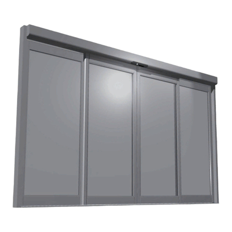
Besam ASSA ABLOY Swingmaster 900 User manual

Besam Swingmaster®900
Service and Installation Manual
Complies with ANSI/BHMA A156.10 standards for power operated pedestrian doors.
UL325 & UL991 Listed
US23-0583-51 1/31/2008


Table of Contents
UImportant InformationU............................................................................................... 1
UImportant Installation InstructionsU.............................................................................. 1
URadio and television receptionU.................................................................................... 1
UIntroductionU............................................................................................................... 3
UHow The Swingmaster WorksU..................................................................................... 3
UOpeningU............................................................................................................... 3
UClosingU................................................................................................................ 3
UImportant Safety InstructionsU................................................................................... 4
UFunction Description of CircuitsU................................................................................... 4
UFunction of KillU...................................................................................................... 4
UFunction of LocksU.................................................................................................. 4
UPush and GoU......................................................................................................... 4
UPower FailureU........................................................................................................ 4
USafety FunctionsU........................................................................................................ 5
UFunction of the Presence Impulse (Approach Side)U........................................................ 5
UFunction of the Presence Detection (Swing Path Side)U.................................................... 5
UFunction of the OPDU.................................................................................................. 5
UPanic FunctionU.......................................................................................................... 5
USafety Functions with SensorsU.................................................................................... 5
UFunction of Door Positioning Device (Cam Set)U.............................................................. 5
UDoor/Operator HandingU............................................................................................. 6
USpring Selection GuideU............................................................................................... 7
UPart Identification & OptionsU..................................................................................... 8
USwingmaster 900 Surface Mount – Side LoadU................................................................ 8
USwingmaster 900 Concealed Mount – Side LoadU............................................................ 9
UArmsU.................................................................................................................... 10
UPushing ArmU....................................................................................................... 10
UPull ArmU............................................................................................................. 11
UConcealed Arm:U.................................................................................................. 11
USpacer Kit:U......................................................................................................... 11
UOptionsU.................................................................................................................... 12
UPush Plates:U........................................................................................................... 12
URemote Push Plates (RF)U......................................................................................... 12
UControl Units and CablesU.......................................................................................... 12
USwitchesU............................................................................................................... 13
ULabelsU................................................................................................................... 13
UTypes of InstallationU................................................................................................ 14
UGeneral Tips / Safety ConcernsU................................................................................ 15
USummary InstallationU............................................................................................... 15
UFastening RequirementsU.......................................................................................... 16
UTest EquipmentU........................................................................................................ 16
UTools RequiredU......................................................................................................... 16
UPre-installation AdjustmentsU.................................................................................... 17
UCam AdjustmentU..................................................................................................... 17
UChanging the Hand of the OperatorU........................................................................... 17
UAdjustment of built-in mechanical full open door stopsU................................................. 18
U(A) Left Hand Overhead ConcealedU........................................................................ 18
U(B) Left Hand Surfaced AppliedU.............................................................................. 18
U(C) Right Hand Overhead Concealed and Surfaced AppliedU........................................ 18
UCam Switch Harness DetailU................................................................................... 19
UConcealed InstallationU............................................................................................. 20
UInstallation for Center Pivot DoorsU........................................................................... 21

UInstallation of Side-Load Header and Operator in Installed FrameU............................. 23
UInstallation of Side-Load Header and Operator in Uninstalled FrameU........................ 23
UMounting the Bottom PivotU....................................................................................... 23
UInstallation of Door LeafU.......................................................................................... 23
UMounting the bottom pivotU....................................................................................... 24
UInstallation of Door LeafU.......................................................................................... 24
USurface Mount InstallationU....................................................................................... 25
UModelsU.................................................................................................................. 25
USurface Mount InstallationU....................................................................................... 26
UArm Systems (Surface Applied)U................................................................................ 27
USurface Mount Installation – PushU........................................................................... 28
UPushing Arm System, (single)U................................................................................... 28
UPush Arm System (double)U...................................................................................... 29
USurface applied dual push.U.................................................................................... 29
UPull Arm System, (single)U..................................................................................... 30
USurface applied double pullU................................................................................... 31
USurface applied dual egressU.................................................................................. 32
UMounting the Arm SystemU........................................................................................ 33
UPush Arm SystemU................................................................................................... 33
UPull Arm SystemU..................................................................................................... 33
UBottom Load InstallationU.......................................................................................... 34
UParts and installationU............................................................................................... 34
UBottom Load InstallationU.......................................................................................... 35
UElectrical Connections and AdjustmentsU................................................................... 36
UConnectionsU........................................................................................................... 36
UPairs of Doors (2 – CU2 Controls Required)U................................................................ 37
UAdjustmentsU.......................................................................................................... 38
UPotentiometersU................................................................................................... 39
ULED Indications & Terminal DescriptionsU................................................................. 40
UTerminal DescriptionsU.......................................................................................... 41
UPlugs on the control boardU.................................................................................... 42
UInstallation of CUHubU........................................................................................... 43
UANSI / BHMA A156.10U............................................................................................. 44
USwinging DoorsU...................................................................................................... 44
U6. Guide RailsU..................................................................................................... 44
U8. SensorsU.......................................................................................................... 45
U10. Entrapment ProtectionU.................................................................................... 47
U11. SignageU........................................................................................................ 48
UAPPENDIX E-4 MAINTENANCE (NOT PART OF ANSI/BHMA 156.10)U............................. 49
UTroubleshootingU....................................................................................................... 50
UFrequently Asked QuestionsU..................................................................................... 52
UPlanned Maintenance ChecklistU................................................................................ 53
USpare PartsU.............................................................................................................. 54
UWiring DiagramsU...................................................................................................... 59
UCU2 Backward Compatibility with LO21BU.................................................................... 59

Besam Entrance Solutions 1 1/31/2008
0BImportant Information
28BImportant Installation Instructions
WARNING - To reduce the risk of server injury or death, material damage and malfunction of the
product, the instructions contained in this manual must be strictly observed during installation,
adjustment, repairs, service, etc. Only Besam trained technicians should be allowed to carry out these
operations.
29BRadio and television reception
This equipment generates and uses radio frequency energy and if not installed and used properly in
strict accordance with the manufacturer's instructions, may cause interference to radio and television
reception. It has been designed to comply with the emission limits in accordance with EN 50081-1
(US market FCC Part 15), which are designed to provide reasonable protection against such
interference in a residential installation. However, there is no guarantee that interference will not
occur in a particular installation. If this equipment does cause interference to radio or television
reception, which can be determined by turning the equipment off and on, the user is encouraged to
try to correct the interference by one or more of the following measures:
• Re-orient the receiving antenna.
• Relocate the receiver with respect to the equipment.
• Move the receiver away from the equipment.
• Plug the receiver into a different outlet so that equipment and receiver are on different branch
circuits.
Plug the receiver into a different outlet so that equipment and receiver are on different branch
circuits.
If necessary, the user should consult the dealer or an experienced radio/television technician for
additional suggestions.
Note!
Besam follows a policy of advancements in development.
Instructions, design, specifications and illustrations, which are contained in this manual, are not
binding. Rights are reserved for changes without previous notice.
Note!
The glazing material in all unframed swing doors shall comply with the requirements in the
Performance Specifications and Methods of Test for Safety Glazing Material Used in Buildings,
ANSI Z97.1. Glazing materials for other pedestrian doors shall also comply with ANSI Z97.1,
except that single strength or heavier glass may be used for those portions of doors involving a
glazed area of less than 1sqf and having no dimension greater than 18”.
Table of contents
Other Besam Door Opening System manuals
Popular Door Opening System manuals by other brands

Alutech
Alutech TR-3019-230E-ICU Assembly and operation manual

Pamex
Pamex KT-INP35 Installation instruction

MPC
MPC ATD ACTUATOR 50 ATD-313186 Operating and OPERATING AND INSTALLATION Manual

Chamberlain
Chamberlain T user guide

Dorma
Dorma MUTO COMFORT M DORMOTION 50 Mounting instruction

Fireco
Fireco Dorgard operating guide