Relcross 9130 User manual

Page 1 of 24 February 2006 Ver 0
9100 Series
Relcross
9100 Series
Installation Instructions
www.relcross.co.uk

Page 2 of 24 February 2006 Ver 0
1. GENERAL.................................................................................................................. 2
2. REPLACEMENT PARTS AND SYSTEM COMPONENTS ................................... 2
3. PRE-INSTALLATION SITE AND PRODUCT CHECK ......................................... 4
4. OPERATOR INSTALLATION ................................................................................. 5
5. WIRING...................................................................................................................... 7
6. ARM AND COVER INSTALLATION ..................................................................... 8
7. OPERATIONAL CHECK ........................................................................................ 11
8. OPERATOR ADJUSTMENT .................................................................................. 12
9. RELEASE FOR SERVICE ...................................................................................... 15
10. 9100 SERIES VER 4.0 SOFTWARE...................................................................... 16
1 GENERAL
The 9100 is an automatic electromechanical swing door operator for use on
Hinged, centre pivoted, and offset pivoted doors. The controller is a microprocessor based
system, tracking the door position at any time during the cycle. When activated the 9100
drives the door to the full open position creating the potential energy in the
spring. When closing the electrical power is reduced and the door closes by controlling
the potential energy release in the spring force. The activating circuit opens the door from
any position on the closing swing. During power failure the 9100 acts as a manual
door closer (size 3). Door opening and closing cycles, including opening speed, back
check speed, hold open time delay, closing speed, and latch position are adjustable.
WARNING
Always disconnect main power to the operator prior
to servicing or cleaning
Warning
.
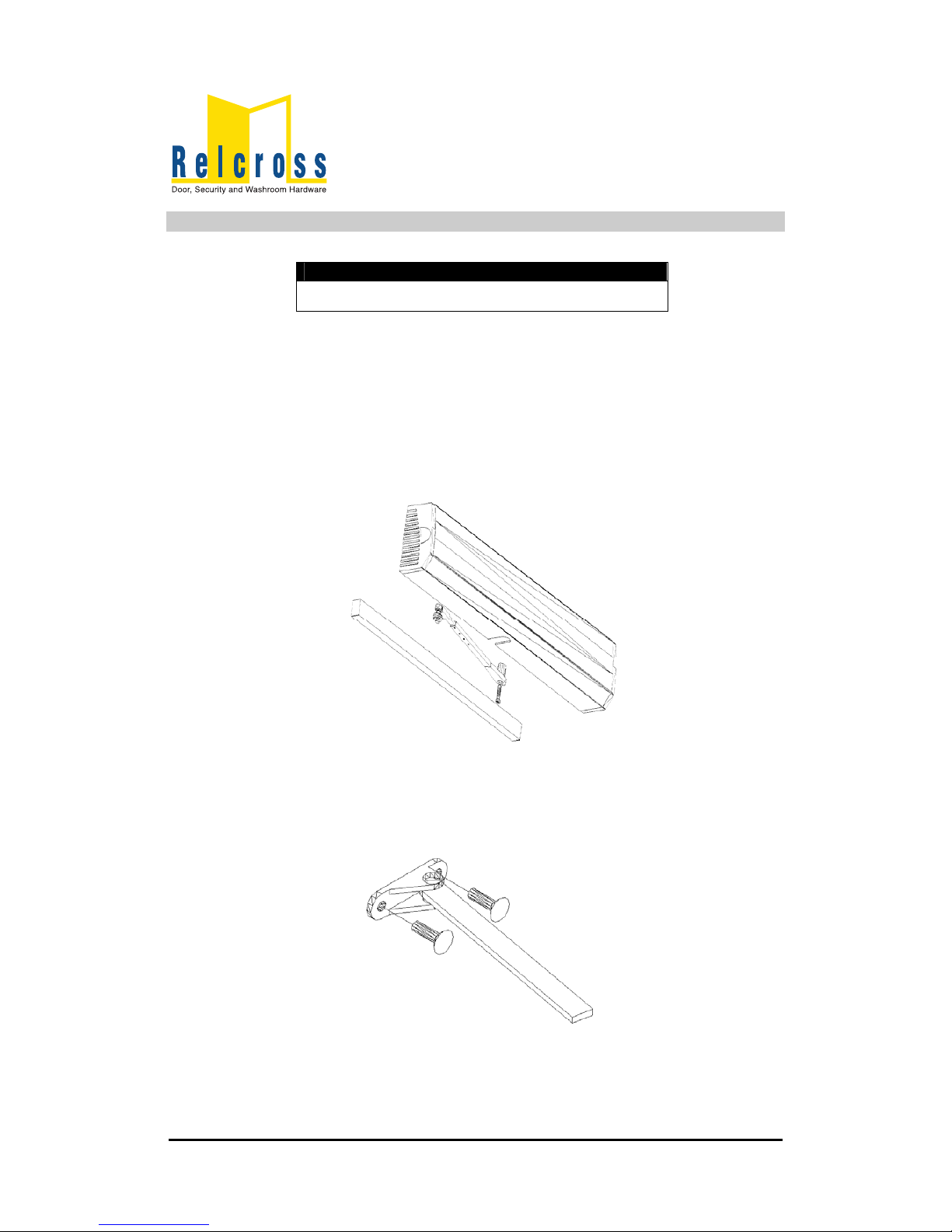
2 REPLACEMENT PARTS AND SYSTEM COMPONENTS
Description Part No
Control Box 710026 – XXX
Gear Box 9100-000
Cover 2550.CP.SA (95171-975R)
Pull Arm Assembly 2550.T.AP.SE (95005-975)
Push Arm Assembly 2550.AP.SE (95085-975)

Page 3 of 24 February 2006 Ver 0
REPLACEMENT PARTS AND SYSTEM COMPONENTS (Cont)
Swing Door Operator Swing door operator
Pull arm and track assembly Push arm assembly
9130 9140

Page 4 of 24 February 2006 Ver 0
3 PRE-INSTALLATION SITE AND PRODUCT CHECK
3.1 Check that the product model is correct for the required application
3.2 Check that all parts listed for the installation are received
3.3 Check architectural drawings and final approved shop drawings for position of
frame and structural openings
3.4 Check header and frame dimensions and required clearances
Clearances for pull system Clearances for push system
3.5 Ensure door weights is less than 90Kgs for heavier doors, consult supplier
3.6 Check that a 240 Volt, single phase, 60 Hz, fused supply (5 amp fuse maximum) is
available at the side of the jamb within approximately 1 Meter of the header.
Approved type conduit is recommended for 240V systems
3.7 The supply must be a dedicated circuit from the main circuit breaker panel and must
not be connected into building lighting circuit with fluorescent lights

Page 5 of 24 February 2006 Ver 0
4 OPERATOR INSTALLATION
4.1 Remove control box from mounting bracket, then remove Motor/Gearbox from
bracket
4.2 Prepare header frame Pull system …………………See Page 5
Push system…………………See Page 6
NOTE
NOTE
For push units with a reveal greater than 150 mm refer
to installation sheet included in the extended arm
Packaging.
4.3 Install operator-mounting bracket on the header/frame.
4.4 Install motor/gearbox on operator mounting bracket, then install control box on
bracket Go to wiring page 7
Pull System
Framed Header and Door Preparation

Page 6 of 24 February 2006 Ver 0
OPERATOR INSTALLATION (Cont)
Push System
Framed Header and Door Preparation
REVEAL Butt Hung/Offset Pivot
DIM A
Centre Pivot
DIM A
25. 559 686
51 533 660
76 508 635
102 483 610
127 457 584
152 457 584

Page 7 of 24 February 2006 Ver 0
5 WIRING
C
CAUTION
• Make sure all wires are properly dressed and secured to prevent interference
• Route all wiring away from moving parts, sharp edges, and heat sources
• Use copper conductors only
• Do not modify the factory wiring or connect into existing electrical circuits or
devices
AUTION
5.1 Refer to the appropriate wiring diagram for the standard control box (Page 22) or the
diagram supplied for custom applications. And connect the following cables
•Ground cable (Ground the operator properly with the earth from main
supply
•Hall effect Cable (do not wrap the hall effect cable around the motor
cable)
•Motor power cable (do not wrap the motor cable around the hall effect
cable)
•Control box power cable
5.2 Connect Activate, Safety, Key switch, and lock accessories as needed. Refer to the
accessory instruction s for any accessories used. Do not connect any remote
activating device to the door unless it is located within line of sight of the door
5.3 When wiring is complete go to “Arm and cover installation” on page 8

Page 8 of 24 February 2006 Ver 0
6 ARM AND COVER INSTALLATION
WA
WARNING
• Keep hands, clothing, wires, tools, ETC away from the
operator motor when the operator is turned on
RNING
6.1 Make sure the operator power switch is turned OFF
6.2 Install a jumper across the control box MAIN ACT T28 and COMMON T27
6.3 Turn the operator power switch on. The operator motor will activate and drive to the
full open position.
6.4 Attach the arm to the operator spindle loosely with the 8-mm socket head screw (for
push systems ensure adjusting boss is inserted correctly).
6.5 Attach the arm to the door
6.5.1 For push systems attach the push arm shoe to the door

Page 9 of 24 February 2006 Ver 0
ARM AND COVER INSTALLATION (Cont)
6.5.2 For pull systems, slide the pull arm roller into the track, insert a track cap
on each end of the track, and attach the track to the door.
Pull Arm
6.6 Adjust the arm
6.6.1 For pull systems, remove the locking screw from the arm
6.6.2 For the push system remove the locking screw from the arm
Pull Arm Push Arm
6.6.3 Keep the door in the full open position and adjust the arm length as
necessary to align the door at 90 degrees from closed. When the arm is adjusted to
the correct length, tighten up the8 mm socket head screw that secures the arm to
the operator spindle and ensure this is secure, then tighten the arm locking screw
6.7 Turn off the power operator switch. The door closes
6.8 Remove the jumper from the control box T27, T28
6.9 Test the operator (See operational check” on page 11) and continue with step 6. 10
6.10 Adjust the operator as required( see “Operator Adjustment” on page 12) and
continue with step 6.11

Page 10 of 24 February 2006 Ver 0
ARM AND COVER INSTALLATION (Cont)
6.11 Snap optional end cap insert (from screw bag) into the end cap opposite the on/off
switch.
6.12 Install the cover assembly on the operator
6.13 Release the operator for service ( see “Release for Service” on page 14)

Page 11 of 24 February 2006 Ver 0
7 OPERATIONAL CHECK
7.1 Set the Key switch to Auto (1 Way) and turn on the operator power switch
7.2 Activate the operator using the activation device, the operator will perform
one sizing cycle
Sizing cycle:
Occurs after a legitimate activation signal is received, after power has been
turned on. During the size cycle, the door opens and closes one time
7.3 If the door does not open at all during sizing cycle
•Check door for binding
•If an electromechanical lock is being used, check that the lock
disengages before the operator opens the door.
•Check fuses, Circuit breakers, and connections.
•Adjust the operator and check door operation (See “Operator
Adjustment on page xx)
Opening speed 75%
Back check speed 75%
Hold open time delay Minimum
Latch position Maximum
Closing speed 50%
SW1 1,2,3,4 OFF
7.4 If the door does not open fully during size cycle
•Check the door for binds
•Increase the back check speed slightly and check door operation
continue increasing back check speed until door opens fully
7.5 If the door slams open decrease the back check speed slightly and check door
operation. Continue decreasing back check speed until the door opens without
slamming
7.6 After the sizing cycle is complete and the doors are closed, apply a maintained
activation signal and check that the door remains open while the signal is applied.
7.7 If a door safety device is being used:
7.8 Door open safety
When the door is in the closed position activate the safety device,
then try to activate the door the door should remain closed.
Activate the door, as the door is opening activate the safety device the
door should stop, and then slowly drive to the full open position.
7.9 Door close safety
Activate the door then maintain activation of the safety device, the
door should open and remain open.
As the door is closing activate the safety device, the should re-open
to the open position time out and close
7.10 When the door is operating properly, continue with step 6.10 on page 9

Page 12 of 24 February 2006 Ver 0
8 OPERATOR ADJUSTMENT
See table below and diagrams on page 16 for operator feature adjustment. After
adjustment, cycle the door several times and check for proper operation, then continue
with step 6.11 on page 10.
N
NOTE
Adjust operator for the slowest operation practical in accordance with the latest BS 7036
standards for power assisted low energy power operated doors.
Opening speed 5 sec’s or more Closing speed 3 sec’s or more
OTE
Features Control Description Anti-
Clockwise
Clockwise
Opening
Speed
P1 Controls opening speed of door Slower Faster
Back Check
Speed
P2 Controls speed of door near full
open position prevent door
slamming
Slower Faster
Hold Open
Time Delay
P3 Controls length of time door
remains in the full open
position 1 to 30Sec
Less time
1 Sec
`More Time
30 Sec’s
Auto
Reverse
setting
P4 Sets pressure required on door
opening before door stops
Less Pressure
required
More
Pressure
Required
Latch
Position
P5 Determines distance at which
the door begins to decelerate to
full closed position to prevent
door slamming
Less Latch More Latch
Closing
Speed
P6 Controls closing speed of door Slower Faster
Safety
Opening
Angle
P7 Controls the angle during the
open cycle that safety operates
Closer to
closed
position
Further from
closed
position
Safety
Closing
Angle
P8 Controls the angle during the
close cycle that safety operates
Closer to open
position
Further from
open
position
Delayed
Activation
SW1
Push And
Go
SW2 When switched on pushing the
door open by 5 degrees causes
the operator to open for the
remainder of the open cycle
Power
boost On or
OFF
SW3 Enables or disables Power Boost
which gives a force in the closed
direction when the door is
closed. Used for high wind
situations
Power
boost
continuous
or 5 Sec’s
SW4 Enables power boost to operate
continuously or for 5 Sec’s only
after door closes.

Page 13 of 24 February 2006 Ver 0
OPERATOR ADJUSTMENT (Cont)

Page 14 of 24 February 2006 Ver 0
P8
P7 P4
P5
P3
P1
P2P6 +
FastSlow
-
REVERSE
TIME DELAY
ON OFF
F
0
ON OFF
SPEED
-
Less +
BACKCHECK
ANGLE
SAFETY (SAF)
LATCH
POSITION
+-
-
Slow +
More
AUTO
-
Short
+
C
B
DFUNCTION
SELECTOR
-
Close Only +
Thru Arc
OPEN
+
Thru Arc
-
Slow
-
Open Only
Fast
+
SPEED
SAFETY (ACT)
ANGLE
CLOSE SPEED
987
A
E
F1
0
6
4
5
2
3
P/B
PNG
ON OFF
CONT P/B 5 SECS
N/A
Long
Less
Fast
More

Page 15 of 24 February 2006 Ver 0
9 RELEASE FOR SERVICE
9.1 Remove all tools, installation equipment, and debris from the vicinity of the door.
9.2 Install all safety, traffic control, and instruction labels on the door as required by the
latest BS 7036. Failure to do this leaves the installer LIABLE for any accident that
might occur. This must be done.
9.3 Verbally instruct the owner or person in charge of the proper operation of the door.
9.4 Instruct the owner or person in charge to routinely inspect the door for the following
•Occasional damage
•Developing problems
•Minor preventative maintenance
9.5 Instruct the owner or people in charge who and where to call for service and
maintenance when required.
IMPORT
IMPORTANT
Make sure to install all safety, traffic control
and instruction decals on the door as required
ANT

Page 16 of 24 February 2006 Ver 0
10 9100 SERIES VER 4.0 SOFTWARE
10.1. OPERATION.................................................................................................... 17
10.1.1. Sizing ............................................................................................................ 17
10.1.2. Auto Reverse on open................................................................................... 17
10.1.3. Standard operation ........................................................................................ 18
10.2. FUNCTION SELECTION................................................................................ 18
10.2.1. Standard (0)................................................................................................... 18
10.2.2. Lock in OFF Only (1) ................................................................................... 18
10.2.3. Lock in 1 Way Only (2)................................................................................ 18
10.2.4. PNG in OFF (3) ............................................................................................ 18
10.2.5. Door closes and Unlocks in Fire Alarm (4).................................................. 18
10.3. FUNCTION CHART........................................................................................ 18
10.4. CONTROL BOX SETUP ................................................................................. 18
10.5. 9100 Series WIRING ........................................................................................ 18

Page 17 of 24 February 2006 Ver 0
10.1 OPERATION
10.1.1 Sizing
From start up (size) the door will activate from morning
entry (24Hrs,T9, T10) regardless of key switch position, 1
Way input (T27,T28) with key switch in one way. 2 Way input
(22, T23) with key switch in two way, or key switch Hold
Open. The first movement will be in the open direction - The
speed of the sizing cycle is automatic and cannot be set from
a potentiometer the door drives opened to the full open
position where the system sets the counter to full open. The
door closes at close speed then latch up to closed position
where the system sets the counter for closed position. From
these two parameters opened and closed position the system
calculates all the other parameters it requires for normal
operation i.e. latch position back check position etc.
• Notes
If the encoder is connected for opposite direction or
faulty or disconnected the door will operate erratically
continuously opening ½ way closing latching and re-opening.
This will continue to occur until power is switched off
10.1.2 Auto Reverse on open
The auto reverse open is set from the Back check
position pot. This sets the level of current required to trip the
door as it is opening.

Page 18 of 24 February 2006 Ver 0
Normal operation
Key switch, activation, morning entry/fire alarm, locking, and safety.
10.1.3 Standard operation
Upon a legitimate activation signal the door
accelerates up to open speed, monitoring the current load on
the drive output. (If the current reaches a level above the set
datum the door will stop and close). The door travels at the
set speed (Potentiometer setting) until it reaches the set back
check position, where the speed (Potentiometer setting) is
decreased to back check speed. When the door stops at hold
open position the system sets the hold open speed and holds
the door open until activation and or timer is cleared. The
door will then close at close speed, (Potentiometer setting)
up to latch position (Potentiometer setting). Where the speed
is decreased by driving the motor in the open direction (fixed
setting), the power is set such that the spring will overcome
this power and continue to allow the door to close up to the
closed position. During the open cycle the safe opening (T1,
T1) is active and the Safety side Adj Pot sets the angle at
which the sensor is redundant, this can be set from Closed
up to back check position. During the closing cycle the safe
closing (T5, T6) is active and the Activate side Adj pot sets
the angle the sensor is redundant, this can be set from
Opened up to a few degrees of closed position.

Page 19 of 24 February 2006 Ver 0
General
24Hr operates the door regardless of key switch
position the door will drive open and remain in the open
position as long as the contact is made (Program 4 is the
exception) Key switch position OFF no activation or safety
operates. Electric lock operates when door closed dependant
upon function selection Electric lock operation is set from
the function selector the time delay is fixed
Key switch Position 1 Way the activation from internal
Activate (T27, T28) safety operates. Electric lock operates
when door closed dependant upon function selection
Key switch Position 2 way the activation from internal
Activate (T27, T28) and external Activation (T22, T23) safety
operates. Electric lock does not operate when door closed
Key Switch H.O The door operates to the open position
and remains in the open position safety is by passed (If
safety activated the door will open slowly)

Page 20 of 24 February 2006 Ver 0
10.2 FUNCTION SELECTION
10.2.1 Standard (0)
Operates as a standard door with electric lock
operating in OFF and 1 WAY
Eyetech Act T5, T6
Eyetech Saf T1, T2
F/A T9, T10
1 Way T27, T28
2 Way T22, T23
Door open T14
Key switch off T12
T8 Not Used
10.2.2 Lock in OFF Only (1)
Operates as a standard door with electric lock
operating in OFF only.
This selection will give a fast activation in Auto or 1
Way from closed as there is no delay for lock operation.
10.2.3 Lock in 1 Way Only (2)
Operates as a standard door with electric lock
operating in 1 Way only
10.2.4 PNG in OFF (3)
Operates as a standard with Push & Go operating in
key switch OFF
10.2.5 Door closes and Unlocks in Fire Alarm (4)
Operates as a standard Fire Alarm Normally closed if
open circuit door closes and will remain Unlocked
Other manuals for 9130
1
This manual suits for next models
1
Table of contents
Other Relcross Door Opening System manuals
Popular Door Opening System manuals by other brands

Synergy Hardware
Synergy Hardware S500 Series Fixing instructions

GEZE
GEZE Slimdrive EMD Replacement instructions

Dorma
Dorma 8916 FT manual

Stanley
Stanley Dura-Glide 2000AG Series Installation Instructions, Quick Reference Guide

Dormakaba
Dormakaba ED50 installation instructions

Roger Technology
Roger Technology SMARTY Series INSTRUCTIONS AND RECOMMENDATIONS FOR THE INSTALLER