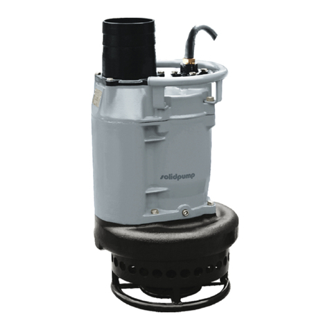
Solidpump TBZ Series Installation and operating instructions

Solidpump Europe SIA
Uriekstes iela 14a
Rīga, LV-1005
LATVIA
Tel.: + 371 66164228
E-mail: [email protected]
www.solidpump.com
Declaration of Conformity
Tha
the operating instructions before use, and safe keeping.
TBZ / TBZE series
Subm e r s i b l e D r a i nage pum p
OPERATION & SERVICE MANUAL
SOLIDPUMP EUROPE SIA

INTRODUCTION
Thank you for selecting the TBZ/TBZE Series Solidpump
Submersible General Dewatering Pump.
This manual explains how to use this equipment and give
instructions on precautions to take during the use. In order to
understand the features of the TBZ/TBZE Series and to use it in
the most effective manner, read this manual before using the
pump.
This equipment should not be used for applications other than
those listed in this manual. In the event of a malfunction or an
accident, the manufacturer will not assume any liability. We
recommend that after you read this manual, you keep it on hand
so that you may be able to refer to it later.
In case you lend this equipment to someone, be sure to also
lend this manual together with the equipment.
In case this manual is lost or damaged, contact with the dealer
from whom you purchased the equipment or the Solidpump
Europe SIA sales office in your area.
This manual was prepared with the utmost attention to details.
However, if you find any errors or omissions, contact with the
dealer from whom you purchased the equipment or the
Solidpump Europe SIA sales office in your area.
The contents of this manual may not be copied, in whole or
part, without consent of Solidpump Europe SIA.
Contents
1.Introduction
1
Safety terminology and symbols 1
P r oduct w a rranty 2
S a f e t y 3
U s e r s a f e t y 3
E nvironmenta l safety 4
2.Product description
4
P u m p desi g n 4
I n t ended u s e 5
The data pl a te 5
P u m p par t nam e s 6
TBZE technical data and function 7
3.Prior to use
8
Inspect the product 8
Inspect the specification 8
Product specification 8
Method of starting 8
4.Installation
9
Preparation for installation 1 0
Install the pump 1 0
Make the electrical connections 1 2
G r oundi n g 1 3
C onnecting the c abl e s 1 3
5.Operation
1 5
B e f o r e oper a t i o n 1 5
T r i a l oper a t i o n 1 6
O per a t i o n 1 7
M o t o r
pro t ec tio n
system
1 8
Water level during operation 1 9
6.Maintenance and inspection
20
I nspect i o n 2 0
S t o r age2 1
M a i n t enance2 1
Disassembly and reassembly procedure 2 2
7.Trouble s hooting
2 5

1. Introduction
Purpose of this manual
The purpose of this manual is to provide necessary information for:
Installation
Operation
Maintenance
CAUTION:
Read this manual carefully before installing and using the product.
Improper use of the product can cause personalinjury and damage
to property and may void the warranty.
aaa
NOTICE:
Save this manualfor future reference, and keep it readily
available at the location of the unit.
(1) Safety terminology and symbols
About safety messages
It is extremely important that you read, understand, and follow the safety messages
and regulations carefully before handling the product. They are published to help prevent
these hazards:
Personal accidents and health problems
Damage tothe product
Product malfunction
Hazard levels
Hazard level
Indication
DANGER:
A hazardous situation which, if not avoided, will result in
death or serious injury
WARNING:
A hazardous situation which, if not avoided, could result in
death or serious injury
CAUTION:
A hazardous situation which, if not avoided, could result in
minor or moderate injury
NOTICE:
A potential situation which, if not avoided, could
result in undesirable conditions
A practice not related to personal injury
Hazard categories
Hazard categories can eitherfall under hazard levels or let specific symbols
replace the ordinary hazard level symbols. Electrical hazards are indicated by
the following specific symbol:
Electrical hazard:
These are examples of other categories that can occur, They fall under the
ordinary hazard levels and may use complementing symbols:
Crush hazard
Cutting hazard
Arc flash hazard
(2) Product warranty
Coverage
Solidpump undertakes to remedy the following faultsin products sold by Solidpump under
the following conditions:
The faults are due to defects in design, materials or workmanship.
The faults are reported to a Solidpump representative within the warranty period.
The product is used only underthe conditions described in this manual.
The monitoring equipment incorporated in the product is correctly connected and in use.
All service and repair work is done by personnel authorized by Solidpump.
Genuine Solidpump parts are used.
Limitations
The warranty does not coverfaults caused by the following:
Deficient maintenance
Improperinstallation
Modifications or changestothe product and installation carried out without consulting
Solidpump
Incorrectly executed repair work
Normal wear and tear
Solidpump assumes no liabilityfor the following:
Bodilyinjuries
Material damages
Economic losses
Warranty claim
Solidpump products are high-quality products with expected reliable operation and long life.
However, should the need arise for a warranty claim; please contact your Solidpump
representative.
Spare parts
Solidpump guaranteesthat spare parts will be available for 10 years after the manufacture
of this product has been discontinued.
NOTICE:
When purchasing pump parts please provide product code showed at the nameplate.
1 2

(3) Safety
WARNING:
The operator must be aware of safety precautionsto prevent physical injury.
Any pressure-containing device can explode, rupture, or discharge its contents
if it is over-pressurized. Take all necessary measures to avoid over--pressurization.
Operating, installing, or maintaining the unit in any way that is not covered in
this manual could cause death, serious personal injury, or damage to the
equipment. This includes any modification to the equipment or use of parts not
provided by Solidpump. If there is a question regarding the intended use of
the equipment, please contact an Solidpump representative before
proceeding.
This manual clearly identifies accepted methodsfor disassembling units.
These methods must be adhered to. Trapped liquid can rapidly expand and
result in a violent explosion and injury. Never apply heat toimpellers,
propellers, or their retaining devices to aid intheir removal.
Do not change the service application without the approval of an authorized
Solidpump representative.
CAUTION:
You must observe the instructions contained in this manual. Failure to do so
could result in physical injury, damage, or delays.
(4) User safety
General safety rules
These safety rules apply:
Always keep the work area clean.
Pay attention tothe risks presented by gas and vapors inthe work area.
Avoid all electrical dangers. Pay attention tothe risks of electric shock or arc flash hazards.
Always bearin mind the risk of drowning, electrical accidents, and burn injuries.
NOTICE:
Never operate a unit unless safety devices are installed. Also see specificinformation
about safety devices in other chapters of this manual.
Electrical connections
Electrical connections must be made by certified electriciansin compliance with all
international, national, state, and local regulations. For more information about requirements,
see sections dealing specifically with electrical connections.
Hazardousliquids
The product is designed for use in liquids that can be hazardous to your health. Observe these
rules when you work withthe product:
Make sure that all personnel who work with biologically hazardous liquids are vaccinated
against diseases to which they may be exposed.
Observe strict personal cleanliness.
Wash the skin and eyes
Follow these procedures for chemicals or hazardous fluids that have come into contact
with your eyes or your skin:
Condition Action
Chem i cal s o r
hazardous fluids
in eyes
1. Hold your eyelids apart forcibly with yourfingers.
2.Rinse the eyes with eyewash or running water for at least 15minutes.
3. Seek medical attention.
Chem i cal s o r
hazardousfluids on
skin
1. Remove contaminated clothing.
2. Wash the skin with soap and water for at least 1 minute.
3. Seek medical attention, if necessary.
(5) Environmental safety
The work area
Always keep the station clean to avoid and/or discover emissions.
Waste and emissions regulations
Observe these safety regulations regarding waste and emissions:
Dispose appropriately of all waste.
Handle and dispose of the processed liquid in compliance with applicable environmental
regulations.
Clean up all spillsin accordance with safety and environmental procedures.
Report all environmental emissions tothe appropriate authorities.
Electrical installation
For electrical installation recycling requirements, consult your local electric utility.
Recycling guidelines
Always recycle according tothe guidelineslisted below:
Follow local laws and regulations regarding recycling if the unit or parts are accepted by
an authorized recycling company.
If the first guideline is not applicable, then return the unit or parts tothe nearest
Solidpump representative.
2. Product description
(1) Pump design
FLUID TYPE/TEMPERATURE Work drainage and sand carrying/0 to 40
PUMP
IMPELLER Open
SHAFT SEAL
Double mechanical seal
BEARING
Sealed ball bearing
MOTOR
TYPE,POLES Dry type submersible induction motor 2poles
INSULATION Class F
MOTOR
PROTECTOR(BUILT-IN)
Circle thermal protector( 11kW)
Miniature protector Non-standard parts
LUBRICANT
Turbine oil VG32
DISCHARGE CONNECTION
Hose coupling
3 4

(2) Intended use
The product is intended for moving waste water, raw and clean water. Always
follow the limits given in Application limits (page 9). If there is a question
regarding the intended use of the equipment, please contact a
Solidpump representative before proceeding.
WARNING:
Only Ex-approved pumps may be used in an explosive or flammable environment.
NOTICE:
Do not use the pump in highly corrosive liquids.
(3) The data plate The information of pump model
The information of pump model name
Motor power (kW)
Pump series
Discharging hose inner diam. (mm)
Motor power (kW)
Intelligent control system
Pump series
Discharging hose inner diam. (mm)
(4) Pump part names
NOTE: This diagram shows the part layout of a typical TBZ/TBZE model. The
external appearance and the internal construction may vary slightly,
depending on your particular model.
5 6

(5) TBZE technical data and function
NO Category Set Value
Actuation
Time s
Recovery
Time s
Recovery Mode s
1 phase loss 2
Manuallyrecovery
(Manuallyturn off the
power ---- correct the
power --- turn on the
power, pump works
2 Impeller jam
Double rated
current
0.1
Manuallyrecovery
(Manuallyturn off the
power ---- solve the
problem --- turn on the
power, pump works
3
Phase
sequence
protection
With power
line input
errors, the
work
Manuallyrecovery
(Manuallyturn off the
power ---- switch the
input wire --- turn on the
power, pump works
4
Over-current
protection
1.2 times
rated current
30 300 Automatic recovery
5
Low-voltage
protection
323V 5 300 Automatic recovery
6
Overvoltage
protection
460V 5 300 Automatic recovery
7
Temperature
protection
Winding
0.1
Automatic recovery
(Winding 80±10
8
Water level
control
Stated
otherwise
Note: TBZE Metal head of electrode will be ON when touching the water, OFF when leaving water.
TBZE water-level control mode
a. When the pump is power on, if floating switch ( or water- t means the
pump starts to work.
b. In the running of the pump, if floating switch (or water-
pumps will stop working after 60s continuous working, but if floating switch ( or water-level
-stop.
c. Stop time: After the pump stops for low water-level, it will not start within 60s ( even if
floating switch ( or water-level detector) is ON; unless plug inthe power again after power off)
d. Recovery mode: The pump stops for low water-level, it will start automatically after 60s
when floating switch ( or water-level detector) is ON.
3. Prior to use
(1) Inspect the product
Inspect the package for damaged or missing items upon delivery.
rifythat no damage has occurred during shipment and that
bolts andnuts have not loosened.
File a claim with the shipping company if anything is out of order.
NOTICE:
If the product has been picked up at a distributor, make a claim directlytothe distributor.
(2) Inspect the specification
Check the nameplate of the pump unit to verify that it is the product that you have ordered. Pay
particular attention to its voltage and frequency specifications.
NOTICE:
If you discover any damage or discrepancy, please contact with the
Solidpump dealer from whom you purchased the product or the
nearest Solidpump representative office.
(3) Product specification
CAUTION:
Do not use the product under conditions otherthan those specified. Doing so
may lead to short, electrical shock, or fire, or might inhibit the product from
attaining itsfull potential.
(4) Method of starting
Direct-on-line start
7 8

4. Installation
DANGER:
Disconnect and lock out electrical power before installing or servicing the unit.
7
WARNING:
Do not install the starter equipment in an explosive zone unless it is
explosion-proof rated.
Make sure that the unit can not roll or fall over and injure people or damage property.
WARNING:
Electrical shock hazard. Check that the cable and cable entry have not been
damaged during transport before installing the pump.
NOTICE:
Neverforce piping to make a connection with a pump.
These requirements apply:
Use the pump dimensional drawing in orderto ensure properinstallation.
Provide a suitable barrier around the work area, for example, a guard rail.
Check the explosion risk before you weld or use electric hand tools.
Remove all debris from the inlet piping system before you install the pump.
Always check the impeller rotation before lowering the pump into the pumped liquid.
CAUTION:
The supply voltage variation
a. continuous running: max±5% of the rated voltage.
b. intermittent running: max±10% of the rated voltage .
To use the pump, the water temperature should be between 0 and 40 .
The pump should be used only for pumping plain water. The pump should not
be used to pump fluids such as oil, salt water, or organic solvents.
The pump must never be used to pump explosive liquids and should not be
operated in an area from whom explosive elements might be present.
The pump must not be used in a partially disassembled state.
Do not use the pump in an area where the water pressure exceeds the
values given below, as it may damage the pump, or cause a short or
electrical shock.
Maximum immersion depth
MODEL
Maximum immersion depth
50TBZ(E)1.5 80TBZ(E)1.5
50TBZ(E)2.2 80TBZ(E)2.2 0.5Mpa(5kgf/cm2)-Discharge pressure during use
50TBZ(E)3.7 80TBZ(E)3.7
100TBZ(E)3.7 80TBZ(E)5.5
100TBZ(E)5.5
0.5Mpa(5kgf/cm
2
)-Discharge pressure during use
0.5Mpa(5kgf/cm2)-Discharge pressure during use
100TBZ7.5 150TBZ7.5
100TBZ11 150TBZ11
100TBZ15 150TBZ15 0.5Mpa(5kgf/cm2)
(1) Preparation for installation
Listed below are tools and instruments that are needed toinstall the submersible pump for
general dewatering purpose.
Pre-installation check
Measure the resistance between each of the core wires and the ground wire (yellow/green)to
verifythe insulation resistance of the motor.
NOTICE:
Insulation resistance reference value 30M .
(2) Install the pump
The pump is transportable and intended to operate either completely or partially submerged in
the pumped liquid. The pump is equipped with a connection for hose or pipe.
Run the cable so that it has no sharp bends, is not pinched, and can not be sucked into the
pump inlet.
a. Soft pipe Installation:
Push the hose all the way tothe base
of the hose coupling. Tighten the
hose clamp to secure the hose in
place.
9 10

Handle the pump carefully. When
suspending the pump to raise or to
lower it, attach a wire rope or a chain
to the pump's handle.
Install the pump only in an area that can maintain a proper water level.
NOTE:
For details on the water level necessary for pump operation, refer tothe section on "Water
Level During Operation" on page 20 of this manual.
The discharge hose can be run vertically
or horizontally, but must be without
sharp bends.
(Pump with soft pipe)
When using a hose to provide piping to
the pump, observe the following: Use
the shortest possible length of discharge
hose and minimize the number of bends.
Verify that the end of the hose (discharge
side) is lifted above the water surface. If
the end of the hose is submerged in
water, it may cause the water toflow
back when the pump has been stopped.
If the end of the hose is located at a level
that is lower than that of the source
water surface, water may continue to
flow out even after the pump has been
stopped.
CAUTION:
If an excessive amount of sediment is drawn into the pump, it may cause the pump
to wear, which can lead to current leakage or electrical shock.
NOTE:
Appropriate piping materials must be provided by the user. Piping materials are
not included withthe product.
The pump must be placed upright during operation. If there is a risk that the pump could
be buried under the sediment, place the pump on a base made up of materials such as
concrete blocks.
(3)
Make the electrical connections
General precautions
Electrical hazard:
A certified electrician must supervise all electrical work. Comply with all local
codes and regulations.
Before starting work on the unit, make sure that the unit and the control panel
are isolated from the power supply and can not be energized. This applies to
the control circuit as well.
Leakage into the electrical parts can cause damaged equipment or a blown
fuse.
Keep the end of the motor cable above the liquid level.
Make sure that all unused conductors are insulated.
There is a risk of electrical shock or explosion if the electrical connections are not
correctly carried out or if there is fault or damage on the product.
WARNING:
Do not install the starter equipment in an explosive zone unless it is explosion
proof rated.
Requirements
These general requirements apply for electrical installation:
The mains voltage and frequency must agree with the specifications on the data plate.
The fuses and circuit breakers must have the proper rating, and the pump overload
protection (motor protection breaker) must be connected and set tothe rated current
according tothe data plate and if applicable the cable chart. The starting current in
direct-on-line start can be up to six times higherthan the rated current.
The fuse rating and the cables must be in accordance with the local rules and regulations.
If intermittent operation is prescribed, then the pump must be provided with monitoring
equipment supporting such operation.
11 12

(4)
Grounding
Electrical hazard:
You must ground all electrical equipment. This applies tothe pump equipment,
the driver, and any monitoring equipment. Test the ground lead to verify that it
is connected correctly.
If the motor cable is jerked loose by mistake, the ground conductor should be
the last conductor to come loose from itsterminal. Make sure that the ground
conductor is longer than the phase conductors. This applies to both ends of
the motor cable.
Risk of electrical shock or burn. You must connect an additional ground fault
protection device to the grounded connectors if persons are likely to come into
physical contact withthe pump or pumped liquids.
WARNING:
To prevent damaging the pump and causing current leakage, which may lead to
electrical shock, be sure toinstall the ground wire securely.
CAUTION:
To prevent electrical shock caused by improper grounding, do not connect the
ground wire to a gas pipe, water pipe, lightning rod, or telephone ground wire.
(5) Connecting the cables
These are the requirements tofollow when you install cables:
The cables must be in good condition, not have any sharp bends, and not be pinched.
The sheathing must not be damaged and must not have indentations or be embossed
(with markings, etc.) at the cable entry.
The cable entry seal sleeve and washers must conform tothe outside diameter of the cable.
The minimum bending radius must not be below the accepted value.
If using a cable which has been used before, a short piece must be peeled off when refitting
it so that the cable entry seal sleeve does not close around the cable at the same point
again. If the outer sheath of the cable is damaged, then replace the cable. Contact a
Solidpump service shop.
The voltage drop in long cables must be taken into account. The drive unit's rated voltage
is the voltage measured at the cable connection point inthe pump.
WARNING:
Before connecting the cable to the terminal board, make sure that the power
supply (i.e. circuit breaker) is properly disconnected. Failure to do so may lead
to electrical shock, short, or injury caused by the unintended starting of the pump.
CAUTION:
If the cable must be extended, use an extension cable withthe same or larger
core size as that of the cable that is provided with the pump. Using a cable of
proper size will prevent the motor from attaining itsfull potential or may cause
the cable to overheat, which may lead to fire, current leakage, or electrical shock.
If a cable with a cut or damaged sheath is submerged in water, the water may
enter the pump and cause the motor to short. This will damage the pump,
which may lead to current leakage, or electrical shock, or burn-out.
To prevent the cable from cuts or twists, which will damage the pump and may
lead to current leakage, electrical shock, or fire, be sure that the tires of
vehicles do not run overthe cable.
If the cable must be submerged in water, be sure to mold the connection
portion completely. Failure to do so may lead to current leakage, electrical
shock, or burn-out.
Never submerge the ends of a cable in water.
If the cable must be extended, use an
extension cable with the same or larger
core size as that of the cable that is
provided withthe pump.
To prevent water from entering inside the cable,
be sure to securely mold the cable connection
portion.
To avoid damaging the cable, arrange the
cable run so that the cable is not bent,
kinked, or pressed against a structure.
a. Tighten the ends of the cable securely
against the terminal board.
b. The figure on the right shows howto
connect the cable properly
13 14

Electric circuit
diagrams
5. Operation
Precautions
DANGER:
If you need to work on the pump make sure thatit is isolated from the
power supply and can not be energized.
WARNING:
Never operate the pump without safety devices installed.
Never operate the pump with the discharge hose blocked, or the discharge
valve closed.
Make sure you have a clear path of retreat.
Never work alone.
CAUTION:
If the pump is equipped with automaticlevel control and/or internal contactor,
there is a risk of sudden restart.
Distance to wet areas
Electrical hazard:
Risk of electrical shock. Make sure no one gets closer than 20 m to the unit
when being in contact withthe pumped or mixed liquid.
Risk of electrical shock, This unit has not been investigated for use i n
swimming pools. If used in connection with swimming pools special safety
regulations apply.
(1) Before operation
CAUTION:
Improper voltage and frequency of the power supply will prevent the pump from
attaining its full potential, and may also lead to current leakage, electrical
shock, or fire
Once again, check the nameplate of the pump to verify that its voltage and
frequency are correct.
Check the wiring, power supply voltage, the capacity of the ground leakage circuit
breaker, and the insulation resistance of the motor.
NOTICE:
Insulation resistance reference value 30M . Please refer page 10 for the test method
NOTICE:
Verif
When using a generator, as much as possible avoid operating the pump in conjunction
with othertypes of equipment.
(2) Trial operation
WARNING:
Make sure that the unit can not roll or fall over and injure people or damage
property.
In some installations, the pump and the surrounding liquid may be hot. Bearin
mind the risk of burn injuries.
Make sure nobody is close to the unit when it is started. The unit will jerk in the
opposite direction of the impeller rotation.
CAUTION:
atmosphere. Operating the pump in reverse while it is submerged in water will
damage the pump, which may lead to current leakage, electrical shock, or fire.
NOTE:
Inspect the pump. Checkthat there is no physical damage tothe pump or
cables.
Check the oil level inthe oil housing.
Remove the fuses or open the circuit breaker, and check that the impeller can
be rotated freely.
Check that the monitoring equipment (if any) works.
Operate the pump for a short time (1 to 2 seconds), and then check the correct pump rotation.
WARNING:
Before changing the connections for reverse rotation, make sure that the power
supply (i.e. circuit breaker) is properly disconnected and that the impeller has
stopped completely. Failure to observe this may lead to serious accidents,
including electrical shock, short, or injury.
Use a phase rotation indicator to checkthe correct pump rotation.
NOTICE:
When using a phase rotation indicator, please read the operation manual withit.
15 16

Two ways to check the correct pump rotation
1. By looking at the impeller; the rotation of
the impeller should be counter clockwise
as shown in the picture(1) on the right.
(1)
2. By looking from the top of the pump.Since
the impeller can not be seen,the best way to
check the rotation is check the kick back
motion of the pump when the pump just
starts.The kick back motion of the pump
should be counter clockwise as shown in
the picture (2) on the right.
(2)
Note:For TBZE,you should use a screwdriver
metal body so that the water level
sensor probe and guide rod connected,
otherwise the pump can not start.
To reverse the rotation aboutthree phase, the
following countermeasure must be taken.
COUNTERMEASURE:
Interchange two of the three wires designated U,
V, and W, respectively.
1minutes) and perform the following checks:
Operating current
Use an AC ammeter (clamp), measure the current at the phase U, V, and W that
are connected tothe terminal board.
Operation voltage
Use an AC voltmeter (tester) to measure the voltage at the terminal board.
Power supply voltage tolerance = within ±10% of the rated voltage.
Vibration
CAUTION:
If the pump generates a considerable amount of vibration, noise, or
smell, disconnect the power supply immediately and contact the
dealer where you purchased the equipment or the Solidpump sales
office in your area.
Continue operations if no abnormal conditions are found during the trial operation.
(3) Operation
WARNING:
The pump may be extremely hot during operation. To prevent burns, do
not touch the pump with bare hands.
so may cause injury, electrical shock, short, or fire.
When the pump is not used for a long time, make sure that the power
supply (such as a breaker) is properly disconnected. If the wiring
insulation deteriorates with the power supply connected, it may cause
current leakage, electrical shock, or fire.
WARNING:
During inspection and repair, disconnect the power supply to avoid
starting the pump unintentionally. Failure to disconnect the power
supply may lead to serious accidents including electrical shock, short,
and injury.
During a power outage, disconnect the power supply tothe pump.
Unintentional operation of the pump after power resumption would be
extremely dangerousto people around the pump.
CAUTION:
Unl ess t he cause of a p roble m is removed, the pum p will
repeat the stop-and-go cycle, eventuallyresulting in damage tothe
pump, and causing current leakage and electrical shock. Therefore,
after verifying that the power supply is disconnected, find and correct
the cause of the problem through inspection and repair.
Do not operate the pump at unusually low head, or when the strainer is
clogged with debris. Doing so will prevent the pump from attaining its
full potential, and may also generate abnormal noise and vibration
and cause damage tothe pump, which may lead to current leakage,
electrical shock, and fire.
To protect the motor, if a current overload occurs in the motor or if the motor overheats
under the conditions given below, the pump will stop automatically, regardless of
the water level during operation.
Extreme fluctuation of power supply voltage.
Pump operated under overload condition.
Pump operated at open phase or binding condition.
(4)Motor
protection
system
WARNING:
1. Circle thermal protector
The TBZ pump( 11kW) is equipped with an internal motor protective
device (circle thermal protector).
If an excessive current is detected or the motor overheats, for reasons such as
the following, the pump will automatically stop operating regardless of the
water level, to protect the motor
Change in supply voltage polarity
Overload
Open-phase operation or operation under constraint
17 18

2. Miniature Protector Non-standard parts
built-in type temperature thermal protector is assembled for KBS415KBS422
This protector is embedded inside the motor coil. If the coil should overheat for
any reason, bending of the bimetal of the miniature protector triggers a
signal, which in turn causes an external circuit in the starting console or control
panel to shut off the motor current. When the temperature returns to normal,
the protector is automatically reset, but restarting is controlled from the starting
console or control panel.
WARNING:
A b-contact miniature protector is adopted, which is normally "closed" and goes
to "open" upon overheating.
To protect the motor from current surges, be sure to install a motor breaker,
thermal relay or similar device inthe external starting console or control panel.
(5) Water level during operation
Pay attention tothe water level during the pump operation. The pump will become
damaged if it is allowed to operate dry.
CAUTION:
Do not operate the pump below Continuous running Water Level (C.W.L),
as doing so will damage the pump, causing current leakage and
electrical shock.
The table below shows the water level during operation by output. Make sure
that the water level will not be under these levels.
MODEL C.W.L.
50TBZ(E)1.5 80TBZ(E)1.5
50TBZ(E)2.2 80TBZ(E)2.2 120 mm
50TBZ(E)3.7 80TBZ(E)3.7
100TBZ(E)3.7 80TBZ(E)5.5
100TBZ(E)5.5
150 mm
100TBZ7.5 150TBZ7.5
100TBZ11 150TBZ11
100TBZ15 150TBZ15
190 mm
The water level for the models which is not included in the tables: as per the picture
shown: the lowest water level should submerge the pump strainer
6. Maintenance and inspection
Precautions
DANGER:
Disconnect and lock out electrical power before installing or servicing the unit.
WARNING:
unit can not roll or fall over and injure people or damage property.
Make sure that you follow these requirements:
hand tools.
pressurized. Make sure that the pump is isolated from the system and that pressure is
relieved before you disassemble the pump, remove plugs, or disconnect piping.
Washing the pump
r. Pay
particular attention tothe impeller area, and completely remove any debris from the impeller.
Inspecting the pump exterior
Verifythat the paint is not peeled, that there is no damage, and that the bolts and nuts have not
loosened. If the paint has peeled, allow the pump to dry and apply touch-up paint.
NOTE:
Touch-up paint must be provided by the user. If the pump must be disassembled due
to damage or loose bolts or nuts, contact the dealer from whom you purchased
the equipment or the Solidpump sales office in your area.
(1) Inspection
Interval
Inspection item
Monthly
Measuring insulation resistance
cold Insulation resistance reference value 20Mmin cold .
thermal Insulation resistance reference value 1M min thermal .
NOTE:
The motor must be inspected if the insulation resistance is considerably
lower than that obtained during the last inspection.
Measuring the loaded current
To be within the rated current
19 20

Interval
Inspection item
Monthly
Measuring the power supply voltage
Power supply voltage tolerance
a. continuous running: max±5% of the rated voltage.
b. intermittent running: max±10% of the rated voltage .
Inspecting the impeller
If the performance level has decreased considerably, the impeller may
be worn.
Semi-annually
Inspection of lifting chain or rope
Inspecting and changing oil.
Yearly
Changing the oil and replacing the mechanical seal in the chamber.
Every 12 months or after 6,000 hours of use, whichever comes first.
NOTE:
Contact the dealer from whom you purchased the equipment or the
Solidpump sales office in your area to inspect and replace the
mechanical seal.
Once every
2to 5 years
Overhaul
The pump must be overhauled even if the pump appears normal during
operation. The pump may need to be overhauled earlier if it is used
continuously or repeatedly.
NOTE:
Contact the dealer from whom you purchased the equipment or the
Solidpump sales office in your area to overhaulthe pump.
(2)Storage
If the pump will not be operated for a long period of time, pull the pump up, allow it to dry, and store it indoors.
NOTE:
Be sure to perform a trial operation before reinstalling the pump. If the pump
remains immersed in water, operate the pump on a regular basis (i.e. once a
week)to prevent the impeller from seizing due to rust.
(3) Maintenance
Inspecting oil and Changing oil
Inspecting oil
Designated oil: Turbine oil VG32.
Oil volume : Specified volume.
Remove the oil plug and take out a small amount
of oil. The oil can be extracted easily by tilting the
pump so that the oil plug faces downward. If the oil
appears discolored or intermixed with water, a
likely cause is a defective shaft sealing device
(i.e. mechanical seal), which requires that the
pump be disassembled and repaired.
Changing oil
Remove the oil plug and drain the oil completely.
Pour a specified volume of oil into the oil filler inlet.
NOTE:
The drained oil must be disposed of by waste
disposal contractors in compliance with the
laws of the located where the pump is being used.
The gasket and the O-ring for the oil filler plug
must be replaced with a new part at each oil
inspection and change.
Model
Specified oil
volume(ml)
50TBZ(E)1.5 80TBZ(E)1.5 620
50TBZ(E)2.2 80TBZ(E)2.2
50TBZ(E)3.7 80TBZ(E)3.7
100TBZ(E)3.7 1100
80TBZ(E)5.5 100TBZ(E)5.5
1100
100TBZ7.5 150TBZ7.5
800
100TBZ11 150TBZ11
800
100TBZ15 150TBZ15
800
The oil volume for the models which is not included in the tables :about 80% of
the total oil cylinder capacity (theoretically, the oil level should coverthe mating ring)
The parts listed below are dispensable items. As a rule of
thumb, Use the replacement period as a guide to replacing
these parts.
Part name
Replacement condition
Gasket and O-ring Each disassembly or inspection
Oil seal Each disassembly or inspection or if the sealing lipis worn
Shaft sleeve
When worn
(4)
Disassembly and reassembly procedure
DANGER:
Disconnect and lock out electrical power before installing or servicing
the unit.
WARNING:
A worn impeller and/or pump housing can have very sharp edges.
Wear protective gloves.
CAUTION:
Make sure to perform a trial operation when starting the pump after a
reassembly. If the pump was assembled improperly, it may lead to
abnormal operation, electrical shock, or water damage.
21 22

Disassembly Procedure for TBZ(E) 2.2~5.5kW
Note: before disassembling, be sure to drain the oil from the pump. Models
50TBZ(E)1.5, 80TBZ(E)1.5, 50TBZ2.2, 50TBZ(E)3.7, 80TBZ(E)3.7, 100TBZ(E)3.7,
80TBZ(E)5.5 and 100TBZ(E)5.5 have the same construction. However, models
50TBZ(E)3.7, 80TBZ(E)3.7, 100TBZ(E)3.7, 80TBZ(E)5.5, and 100TBZ(E)5.5 are
constructed without a shaft sleeve.
(1) Removing the strainer stand
Remove the hexagonal nut and the plain washer from the bottom and remove the
strainer stand from the pump.
(2) Removing the suction cover
Remove the hexagonal bolt (except 1.5/2.2 kW), plain washer, and the stud bolt,
plain washer, and remove the suction cover, suction cover packing from the
pump.
(3) Removing the impeller
Using a box wrench, remove the impeller nut, spring washer, and impeller thread
protective cover; then remove the impeller, impeller adjusting washer, shaft
sleeve (except 3.7/5.5 kW) from the main shaft.
(4) If necessary, remove the pump casing, oil seal, O-ring and remove the
mechanical seal. After removing the hexagonal bolt and the spring washer,
remove the pump casing from the pump. At this time, be careful not to damage
the sliding surface of the mechanical seal. Remove the mechanical seal from
the main shaft.
NOTE:
The Exchange or maintenance of mechanical seal must be handled by the
qualified staff. If you find anyomissions, contact Solidpump sales office in your area.
Disassembly procedure for TBZ 7.5~15kW
Note: before disassembling, be sure to drain the oil from the pump. Models
150TBZ7.5, 100TBZ11, 150TBZ11, 100TBZ15 and 150TBZ15!have the
same construction.
(1) Removing the bottom plate and the strainer
After removing the hexagonal nut and the plain washer from the bottom,
remove the bottom plate and the strainerfrom the pump.
(2) Removing the suction cover
After removing the hexagonal bolt, plain washer, stud bolt, and the plain
washer, remove the suction cover and the suction cover packing from the
pump.
(3) Removing the impeller
Using a box wrench, remove the impeller nut, hexagonal nut, and the impeller
thread protective cover; then remove the impeller and the impeller adjusting
washer from the main shaft.
(4) Removing the pump casing
After removing the hexagonal bolt and the spring washer, remove the pump
casing,neck ring, O-ring, and the shaft sleeve from the pump.
(5) Remove the oil casing if necessary, and remove the mechanical seal.
After removing the hexagonal bolt and the spring washer, remove the oil
casing from the pump. At this time, be careful not to damage the sliding surface
of the mechanical seal. Remove the mechanical sealfrom the main shaft.
NOTE:
The Exchange or maintenance of mechanical seal must be handled by the
qualified staff. If you find anyomissions, contact Solidpump sales office in your area.
23 24

Reassembly procedure
The reassembly procedure is the reverse sequence of disassembly.
NOTE:
After completing reassembly, do not forget to pourthe specified amount of
oil into the pump.
The gaskets and O-rings must be replaced with new parts. Also replace
any parts that are worn or damaged.
Using a clean rag without oil, wipe the sliding surface of the mechanical seal. Apply oil to
the outer circumference of the cushion rubbertofacilitate insertion.
NOTE:
For further details on how to install the mechanical seal, refer to the
that is sold separately as a spare part.
After installing the impeller, and after completing the reassembly, check that the impeller
rotates smoothly and that it does not come in contact withthe diffuser.
To make sure that the pump operates normally, perform a trial operation before placing the
pump back into service.
7. Trouble shooting
DANGER:
Personal injury hazard. Troubleshooting a live control panel exposes
personnelto hazardous voltages. Electrical troubleshooting must be
done by a qualified electrician. Failure to follow these instructions will
result in serious personal injury, death, and/or property damage.
WARNING:
Always disconnect and lock out power before servicing to prevent
unexpected startup. Failure to do so could result in death or serious
injury.
Read this operation manual carefully before requesting repair. After re-inspecting
the pump, if it does not operate normally, contact the dealer from whom you
purchased the equipment, or the Solidpump sales office in your area.
Symptom Cause Countermeasure
Pump failsto start
No power is supplied (i. e. power outage) Contact the electric power company or
an electrical repair shop.
Open circuit or poor connection of
the cable.
Check if there is an open circuit in the
cable or wiring.
Automaticallycontrol faults ( control panel) Check the reason and then ask expertstorepair
Impeller is obstructed Inspect the pump and remove the
obstruction
Pump starts but
stops immediately,
causing the motor
protector to actuate
Impeller is obstructed Inspect the pump and remove the
obstruction.
Voltage drop
Correct the voltage to the rated
voltage, or use an extension cable that
meets the standard.
Failure round thermal protector or
protective device
replacement or adjustment
A 50 Hz model is operated at 60 Hz. Check the nameplate and replace the
pump or the impeller.
The strainer is obstructed and the
pump was operated dry for long hours.
Remove the obstruction.
Motor abnormal.
Repair the motor or replace with a new motor.
The pump is picking up too much
sediment.
Place a concrete block under the
pump to prevent the pump from
picking up sediment.
and pumping
volume is lower.
The impeller or suction cover is worn.
Replace.
The hose may be kinked or clogged.
Minimize the number of bends in the
hose. (In an area with a large amount
of debris, use the pump in a meshed
basket.)
The submerge depth of pump is too
shallow, there is air inhalation
Adjust the submerge depth until the
pump is submerged.
Check if the gate valve is open
open gate valve
The straineris obstructed or buried.
Remove the obstruction. Place a
concrete block under the pump to
prevent the pump from picking up
sediment.
The motor rotates in reverse. Interchange the power supply terminal
connection.
The pump generates
noise or vibration
The bearing of the motor may be
damaged.
To replace the bearing, contact the
dealer from whom you purchased the
equipment or the Solidpump sales
office in your area.
The shaft is bending correct or contact with the nearest
agency of Solidpump
25 26

This manual suits for next models
5
Table of contents
Other Solidpump Water Pump manuals
Popular Water Pump manuals by other brands

Sibata
Sibata SIP-32L Operation manual
Rheem
Rheem 310 Series Service instructions
Edwards
Edwards EXT Series instruction manual
Ingersoll-Rand
Ingersoll-Rand ARO PD10 Series Operator's manual

Trebor
Trebor MAGNUM 620D Operation & maintenance manual
Invacare
Invacare CareGuard CG9701 Assembly, installation and operating instructions
HNP Mikrosysteme
HNP Mikrosysteme mzr-7208 operating manual
Finish Thompson
Finish Thompson KC11 Series Installation & maintenance instructions
Espa
Espa PRISMA instruction manual

Aqua
Aqua MSA Series Use and maintenance manual

Jesco
Jesco 43-20406 Operation & maintenance instructions

VEVOR
VEVOR FLO300 installation instructions
