Aqua MSA Series User manual

USE AND MAINTENANCE MANUAL FOR
DIAPHRAGM ACTUATED MOTOR DRIVEN DOSING PUMPS
SERIES
MSA –MSB –MSC

Operating manual
AQUA S.p.A. ENGLISH Page 2
SUMMARY
INTRODUCTION......................................................................................................................................................................................3
RESPONSABILITY LIMITATIONS.......................................................................................................................................................3
VALIDITY.............................................................................................................................................................................................3
ENVIRONMENT AND SAFETY REQUESTS...........................................................................................................................................5
ICONS AND SUGGESTIONS IN THE FOLLOWING INSTRUCTIONS ................................................................................................5
POTENTALLY EXPLOSIVE AREA USE..............................................................................................................................................5
SAFETY VALVE ..................................................................................................................................................................................5
SUITABILITY AND CHEMICAL COMPATIBILITY CHECK...................................................................................................................5
ELECTROMAGNETIC COMPATIBILITY NOTE:..................................................................................................................................5
NOISE LEVELS...................................................................................................................................................................................6
VIBRATIONS.......................................................................................................................................................................................6
HOT SURFACE...................................................................................................................................................................................6
TRANSPORT, MOVEMENT AND STORAGE..........................................................................................................................................6
RECEIVEMENT CHECK......................................................................................................................................................................6
STORAGE...........................................................................................................................................................................................6
TRANSPORTATION AND RAISING ....................................................................................................................................................7
STANDARD PACKAGE.......................................................................................................................................................................7
DESCRIPTION.........................................................................................................................................................................................7
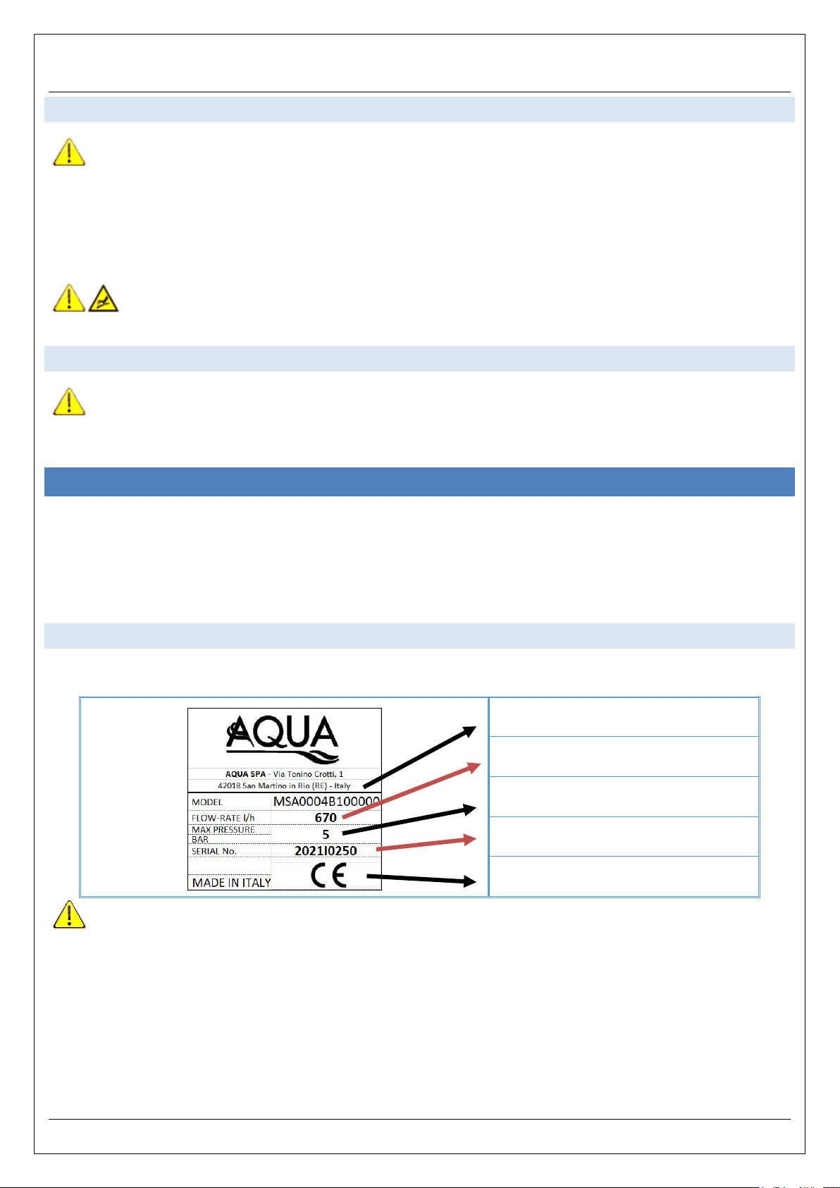
DATA STICKER...................................................................................................................................................................................7
LIQUID END MATERIALS ...................................................................................................................................................................8
FUNCTION PRINCIPLES ....................................................................................................................................................................8
USE RESTRICTIONS..........................................................................................................................................................................9
PREDICTED USE................................................................................................................................................................................9
RATIONALLY PREDICTED WRONG USE ..........................................................................................................................................9
FORBIDDEN USE..............................................................................................................................................................................10
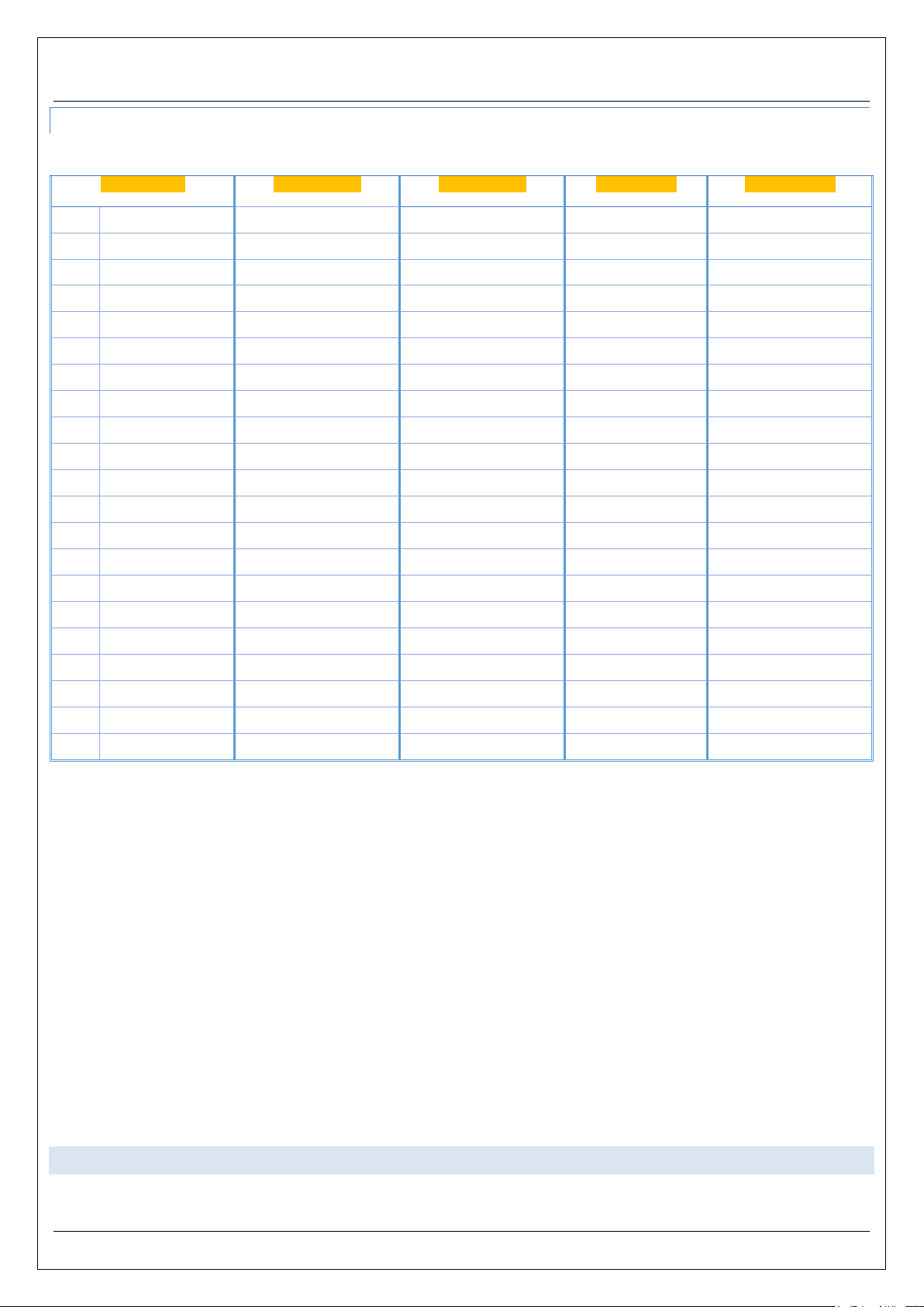
FLOWRATE ADJUSTMENT SYSTEM...............................................................................................................................................10
MANUAL ADJUSTMENT WITH KNOB AND LINEAR VERNIER........................................................................................................10
TECHNICAL DATA............................................................................................................................................................................10
INSTALLATION.....................................................................................................................................................................................11
GENERAL INDICATIONS:.................................................................................................................................................................12
CONNECTION TO PLANT PIPES .....................................................................................................................................................12
ELECTRIC MOTOR CONNECTION ..................................................................................................................................................12
HYDRAULIC PART INSTALLATION..................................................................................................................................................13
SUCTION PIPE..................................................................................................................................................................................14
PROTECTION BY IMPURITIES:........................................................................................................................................................16
LIQUIDS WHIT GAS EMISSIONS:.....................................................................................................................................................16
CALIBRATION POT...........................................................................................................................................................................16
DISCHARGE PIPE.............................................................................................................................................................................16
SAFETY VALVE ................................................................................................................................................................................17
PULSATION DAMPENER..................................................................................................................................................................18
MANOMETER....................................................................................................................................................................................18
START 18
PRELIMINARY CHECKS...................................................................................................................................................................18
STARTING SEQUENCE....................................................................................................................................................................18
MAINTENANCE PROGRAM..............................................................................................................................................................18
PERIODICAL VISUAL CHECK ..........................................................................................................................................................19
PRECAUTIONS BEFORE MAINTENANCE.......................................................................................................................................19
VALVE GROUP REPLACEMENT......................................................................................................................................................19
DIAPHRAGM REPLACEMENT..........................................................................................................................................................20
PUSHING ROD SEAL REPLACEMENT ............................................................................................................................................20
GEARBOX OIL CHECK AND REPLACEMENT. ................................................................................................................................21
MALFUNCTIONS AND possible SOLUTIONS .....................................................................................................................................21
DECOMMITIONING, Disposal and demolition.....................................................................................................................................22
DECOMMITIONING...........................................................................................................................................................................22
DISPOSAL AND DEMOLITION..........................................................................................................................................................22
WARRANTY ..........................................................................................................................................................................................24
REPAIRS TO AQUA ASSISTANCE CENTER....................................................................................................................................24

Operating manual
AQUA S.p.A. ENGLISH Page 3
INTRODUCTION
Thanks for choosing an AQUA product. A careful reading of this manual and its compliance is recommended to preserve product and its safety
requests for a long period.
This machine must be installed and used by qualified personnel, aware of national and plant safety regulations in the installation country.
Noncompliance of the following instruction will void any applicable guarantee. Warranty terms must be moreover completed by local legislative
and technical rules, in force in the country where the product will be installed. Following instructions does not replace any plant regulation or
further additive limitations, even not legislative released as safety instruction.
For a correct manage and maintenance please follow scrupulously the recommendations in this manual.
It is mandatory that technician and maintenance personnel read and understand the instructions in this manual.
The instruction Manual should be stored in a safe and dry place, easy to find and available for further questions consultation in case of needs.
In order to allow easy recognition of important indications, it is recommended to maintain this manual in good conditions (eventually
replacing it) , as like the following alerts present directly on the machine:
•Machine data sticker
•Arrow indicating motor rotation direction
•Maintenance and service stickers
RESPONSABILITY LIMITATIONS
Missed observance of rules present in this manual will release AQUA from any responsibility. For any further question, not explicitly included in this
manual, please contact AQUA technical support.
Dismantling, alterations or general tampering attempts will invalidate the guarantee and will release AQUA by any further responsability
for persons or object damage.
Furthermore, AQUA will not responsible in the following cases:
-Wrong installation;
-Improper machine use;
-Missing observance of installation country rules;
-Missing or incorrect maintenance;
-Non original spare parts or spare parts not specified for the requested machine
-Due to force majeure damages.
VALIDITY
This manual is valid for the following AQUA machines.
Series: MSA –MSB –MSC
Type: 4,9,14,5 ,19,22,7,18,26,34,39,11,27,41,49,54,14,30,40,65,35,75,105,150,50,110,170,250,140,300,430,670,200,450,700,1000.

Operating manual
AQUA S.p.A. ENGLISH Page 4

Operating manual
AQUA S.p.A. ENGLISH Page 5
ENVIRONMENT AND SAFETY REQUESTS
ICONS AND SUGGESTIONS IN THE FOLLOWING INSTRUCTIONS
Metering pumps are machines composed by dangerous parts, so:
•Improper use or tampering,
•Safety devices removal or disconnection,
•Missing or infrequent maintenance
Can provide critical damage to object and personnel
In particular, the staff must be informed about danger deriving from:
Malfunction and/or damages to device or personnel.
Explosions.
Parts in tension
Rotating or moving parts
Corrosive or pressurized pumped
Hot surface
POTENTALLY EXPLOSIVE AREA USE
PDM metering pumps in STANDARD version ARE NOT adequate for potentially explosive areas!
ATTENTION: classified area version must be ordered for this kind of use! In ATEX area require ONLY machines in ATEX execution
with flameproof motor . Such machines are suitable for Group II category 3, in 2/22 Zone purpose (no risks during normal use)
ATTENTION: In any case PDM metering pumps ARE NOT suitable for use in zone 0/20 or 1/21 !
SAFETY VALVE
ATTENTION: Diaphragm metering pumps are volumetric pumps that MUST HAVE an external safety valve installed on the
discharge pipe to protect against overpressures. Working pressure can’t in any case be above the max admittable pressure indicated on
the pump sticker, even during safety valve discharge.
SUITABILITY AND CHEMICAL COMPATIBILITY CHECK
PDM pumps are suitable to LIQUID chemical dosing ONLY. All pumps are supplied in agreement to order request.
PLEASE NOTE: any different use that agreeded with AQUA during the order is not appliable and will cause warranty dissolution.
ELECTROMAGNETIC COMPATIBILITY NOTE:
If correctly installed and directly connected to the power supply, PDM metering pumps respect the limit indicated by electromagnetic rules (EMC
–generic rules for industrial facilities).
Pumps with inverter connection or other electrical components have to be ordered for this use. Customer have to take care about
checks and expedients to comply to those limits.

Operating manual
AQUA S.p.A. ENGLISH Page 6
NOISE LEVELS
Noise levels tested in agreement to European rule 2006/42/CE are reported here below. Used test procedure is the same as described by UNI EN
ISO 3744:2010 rule.
Table value is referred to pumps used within the limits of use and installed accordingly with the instructions contained inthe present operating manual.
METALLIC / PLASTIC LIQUID END MATERIAL
Pump model
Noise pressure level
PDM 250
< 70 dB(A)
PDM 1000
< 75 dB(A)
Employer will have to take care about technical and safety measures needed to reduce risks derived by daily exposition to noises into work
environment and whatever required to guarantee and preserve personnel’s health.
VIBRATIONS
PDM metering pump series are not “human direct contact machines”. Vibrations created are not substantial if installed respecting this manual. They
result anyway under 2,5 m/s2and are not able to create dangerous situations. In case of significant vibration, stop the machine immediately and
contact maintenance service.
HOT SURFACE
Some surfaces may become hot during normal use, especially near the motor and its connection flange to the pump.
Please check that the motor can be enough ventilated and that nearby objects or sunrays will not irradiate it with additional heat.
TRANSPORT, MOVEMENT AND STORAGE
RECEIVEMENT CHECK
AQUA metering pumps are supplied packaged with materials, which protect them against accidental damages during transportation.
In any case, during the reception of the package, Customer should have to verify package integrity.
Eventual damages must be notified to the transporter, and added to the Transport Document Notes.
In case of damages, before starting the machine, please contact AQUA technical assistance.
STORAGE
AQUA recommends to store the machines in their original package.
In any case if not immediately used, pumps have to be stored with adequate protections in warm and dry environment, clean, without vibrations into
and protected against bad weather. Furthermore, be sure to protect from ground humidity by using a raised plan (e.g.: shelf/pallet). Avoid ambient
temperature below - 20°C. If the machine will not be used for a long period, AQUA recommends to load the oil to preserve internal components by
oxidation. Do not stack packages (except when explicitly allowed) in order to avoid damages to the below machine or package tilting and fall, which
may cause injuries. Be sure that the shelf is able to support package weight. Before starting the machine, keep it in warm environment for few hours,
in order to stabilize its temperature to the working conditions.
If required, please notify in advance about special storage conditions, in order to prepare an adequate package.

Operating manual
AQUA S.p.A. ENGLISH Page 7
TRANSPORTATION AND RAISING
During transportation, pumps have to be adequately secured and packaged to protect the contents against accidental hits, falls, or exposition
to humidity. A particular attention is recommended to the pump connection.
Before than transport, oil must be drainer. Every AQUA pump is supplied with a 250 cc plastic bottle. However, after the first opening, the cap must
be sealed with adhesive tape for a perfect lightening.
Standard version (manual adjustment) of PDM metering pumps does not weight above 15kg, therefore can be moved by hand. In case of special
executions, please use an adequate device (trans pallets, forklift, tackle etcetera) according of packages dimension and weight.
ATTENTION: NEVER grab the pumps from their connections! This can damage the pump irreparably and cause leaks and
malfunctions!
STANDARD PACKAGE
Each AQUA pump is packed into a carton box with an appropriate protection guaranteed by a foam system, which completely envelop the
machine during its transport and movement.
DESCRIPTION
PDM metering pumps are composed of:
•A single-phase or tree-phase alternative current electric motor;
•A reduction gearbox which determinate pump stroke/min;
•A liquid end chemically compatible with the pumped fluid;
•A stroke adjustment knob, from 0 to 100% to requested flow rate.
DATA STICKER
Each pump comes with a sticker fixed on the pump body, like the one shown in the below picture:
1 = Pump code
2 = Max guaranteed flow rate (l/h)
3 = Max working pressure (Bar)
4 = Pump serial number.
5= Made in –CE marking
ATTENTION: Keep the data sticker in good reading condition, protecting carefully.
•Mentioned data are mandatory in case of spare parts request, maintenance informations or technical assistance.
•Never remove the sticker by its original position .
•Never edit or falsify the data mentioned in the sticker.
Liquid end materials are indicated as per the below chart, in case of special executions.

Operating manual
AQUA S.p.A. ENGLISH Page 8
LIQUID END MATERIALS
Wetted parts, such as Pump-head, Ball valve, Valve seats, Valves OR and Valve cage, may be made of different materials (as pert the below
chart), according to the chemical compatibility toward the dosed chemical:
PUMP-HEAD
BALL VALVE
VALVE SEAT
VALVES OR
VALVE CAGE
BB
PP
PYREX
PVC
FPM
PP
B0
PP
PYREX
PVC
EPDM
PP
B1
PP
CERAMIC
PVC
FPM
PP
B2
PP
PTFE
PVC
FPM
PP
B3
PP
SS316L
SS316L
FPM
PP
B4
PP
CERAMIC
PVC
EPDM
PP
B5
PP
PTFE
PVC
EPDM
PP
B6
PP
SS316L
SS316L
EPDM
PP
B7
PP
SS316L
SS316L
SILICON
PP
B9
PP
HASTELLOY
INCOLOY
EPDM
PP
FF
PVDF
PTFE
PVDF
PTFE
PVDF
F1
PVDF
CERAMIC
PVDF
PTFE
PVDF
F5
PVDF
HASTELLOY
PVDF
PTFE
PVDF
AA
SS316L
SS316L
SS316L
FPM
PP
A0
SS316L
SS316L
SS316L
EPDM
PP
A1
SS316L
SS316L
SS316L
PTFE
PP
A2
SS316L
SS316L
SS316L
FPM
SS316L
A3
SS316L
SS316L
SS316L
EPDM
SS316L
A4
SS316L
SS316L
SS316L
FPM
SS316L + MOLLA
A5
SS316L
SS316L
SS316L
EPDM
SS316L + MOLLA
A7
SS316L
SS316L
SS316L
SILICON
PP
Non standard execution codification may differ from the above mentioned ones.
FUNCTION PRINCIPLES

Operating manual
AQUA S.p.A. ENGLISH Page 9
PDM series mechanical Diaphragm metering pumps have a spring return mechanism. Their movement is generated by an electric motor through a
gearbox which allow the rotation of an eccentric shaft that axially push a pushing rod connected to the diaphragm, thus generating the Discharge
phase and compressing the spring at the same time. While the rotation of the eccentric continues, the spring extends, letting the rod to go back to its
original position, thus generating the Suction phase. Alternative motion produced by this mechanism allows suction and discharge of the chemical
trough the liquid end with a movement so similar to a syringe piston, while the resulting action of the check valves defines the flow direction. The drive
distance of the pushing rod, and consequently the quantity of dosedchemical, can be modified through the adjustment located behind the pump body.
Theorical flow rate match with pumping part inducted volume. Actual flow rate is lower cause of the volumetric efficiency of the pump, and depends
by pump type and dimensions, liquid nature and viscosity and working pressure.
USE RESTRICTIONS
Admittable project temperature Ta for all pump types is comprehended between -10 °C and +40°C. Maximum temperature of pumped fluid depends
by the liquid end material (as well as the fluid own characteristics)
NOTE: Periodically check the respect of temperatures limits!
Motor power mentioned in the motor plate refers to operation at altitude below 1000m a.s.l. and ambient temperatures between +5°C and
+40°C. In case of installation above 1000m a.s.l., motor power will decrease proportionally, as shown in the below picture:
PREDICTED USE
PDM metering pumps are designated to liquid dosing ( ambient temperature or heated).
Any other use must be considered “IMPROPER USE” and it is not admitted.
AQUA decline any responsibility for any eventual damage.
PDM metering pumps are suitable for a non-continuous duty 12/24 h/day and can be used for the following applications:
-Water and waste water treatment;
-Pharmaceutical manufacturer;
-Food industrial and agro industrial;
-Paper mills;
-Cleaning products manufacturing and dosing;
-CIP plants;
-Potabilization plants.
RATIONALLY PREDICTED WRONG USE
Following uses of PDM pumps have to be considered incorrect:

Operating manual
AQUA S.p.A. ENGLISH Page 10
-Without a safety valve immediately installed after the discharge valve and in any case before than any other accessory;
-Dosing different product than specifically indicated;
-In corrosive and stagnate atmosphere enclosed in not enough ventilated area;
-Pressure dosing without manometer installed (see Discharge pipe- Manometer)
-Powered by inverter or other electric devices (if not specifically requested for this use)
-With motor faster than original (different poles)
-In potentially explosive areas (if not specifically requested for this use)
FORBIDDEN USE
It has to consider forbidden use PDM pumps in mining plants or under water.
Furthermore it is forbidden:
To use the pumps without Safety devices or with the same tampered or out of order
To Use STANDARD version pumps in ATEX areas!
To use PDM pumps in ATEX version in 0/20–1/21 explosive zones!
FLOWRATE ADJUSTMENT SYSTEM
PDM pumps flow rate adjustment is continuous and regular and can be modified with pump working or steady. However it’s easier to adjust when the
pump is working, especially for pumps with large plunger diameter.
MANUAL ADJUSTMENT WITH KNOB AND LINEAR VERNIER
Standard version of PDM metering pumps are supplied with manual micrometric adjustment. Thanks to this adjustment is possible to manage the
flow rate in a very precise way with a fixed stroke progress of 1 mm each turn. This means that if the pump stroke is 4mm, you will be able to complete
the entire stroke in 4 complete rounds from 0 to 100% that can be divided in parts thanks to numbers on the knob.
TECHNICAL DATA

Operating manual
AQUA S.p.A. ENGLISH Page 11
Max flow rate data refers to test with water, ambient temperature of 25°C, height of 250m a.s.l., suction height of 1mt with rigid suction
pipes. Values are valid for operation @50Hz.
INSTALLATION

Operating manual
AQUA S.p.A. ENGLISH Page 12
GENERAL INDICATIONS:
For proper pump operation, it is very important that the valve axis will be perfectly vertical.
Be sure to protect the pump from plant pipes leakages and corrosion. The pump is able to keep and handle the chemical in the
pump-head only! Avoid to install pipings or accessories directly above the pump. Avoid to install the pump in corrosive or stagnant
atmosphere, because the chemical fog may irreparably damage the pump!
In case of outside installation please consider an adequate protection by direct weather action (rain, sun, wind, dust and humidity)
which could significantly reduce machine life. Consider moreover to use a roofing and/or sliding panels that will prominently improve
pump’s efficiency and safety during its whole working life.
Consider sufficient space all around the pump, in order to allow machine inspection and maintenance
CONNECTION TO PLANT PIPES
Do not install the pump directly to cement base. Use a metallic base and ensure that it result stable and levelled to avoid further vibrations.
Pipes must be supported independently, their weight must not lie on the pump in any way, because that will create tensions on the
pump, ruptures and product leaking. Do not tighten too much the piping connection to the pump-head ones, above all in case of pump-
head in plastic materials, in order to avoid ruptures or deformations. To make the dismantling easier, draining connections must be installed in
the discharge piping, near the liquid end.
An internal plant washing is required before connecting the pump to the pipings, with special attention to suction pipe and relevant
supply tank. This procedure will eliminate any solid residues which, if lead into the pump-head, can irreparably damage the pump.
ELECTRIC MOTOR CONNECTION
For ATEX executions refer only to ATEX specific manuals in attachment to the supply!!!
Electric motor usually supplied with PDM pumps is a three-phase motor, at 230-400V tension. Depending by the version, its power can be 0,18 or
0,37 kW at 50/60 Hz. Before connecting it to the power supply, Customer must check that the plant tension complies to the motor plate, to avoid
damages on electric parts. It is also recommended:
•To install always in agreement with the last safety norms;
•To install all necessary motor protection devices (for example a thermal protected switch) NOTE: Fuses are not intended a sufficient
motor protection!
•To guarantee a sufficient space to allow motor cooling, by leaving at least 30 cm from walls and other objects.
•Not to install standard motors into extreme hot environments (ambient temperature >40°C) or at altitudes above 1000m a.s.l. In this cases
an over dimensioned motor is required to balance the loss of performance caused by working environment.
•To check cable gland dimensions and tightening. They have to be adequate to entering cables dimensions in order to preserve the
electric motor box by external agents and guarantee the protection.
•To check motor rotation direction during first start. It should turn in COUNTER CLOCKWISE direction if observed by the top (fan side).
ATTENTION: Wrong cable glands or an insufficient tightening may damage the terminal box, the electric cables and
jeopardize motor protection. In any case, ALWAYS connect the ground wire inside the motor box!

Operating manual
AQUA S.p.A. ENGLISH Page 13
HYDRAULIC PART INSTALLATION
Customer must respect local regulation of the Country where the machine will be installed, independently from what mentioned in this manual.
Here below you can find a general installation scheme:
Metering Pump
Safety valve
Pulsation Dampener
Calibration pot
Manometer
Foot filter valve
3PH MOTOR
COLLEGAMENTO A STELLA
1PH MOTOR
ROTAZIONE SENSO
ORARIO
1PH MOTOR
ROTAZIONE SENSO
ANTIORARIO
3PH MOTOR
COLLEGAMENTO A
TRIANGOLO

Operating manual
AQUA S.p.A. ENGLISH Page 14
Filling system
Counter pressure valve
Filter
Interception valve
SUCTION PIPE
•Pipe length should be reduced at minimum and be as linear as possible, using, where necessary, high range turns. In any case the
maximum total length of all suction sectors should not exceed 2,5 metres;
•Never exceed 1,5 m of suction height in case of overhead installations;
•Presence of air bubbles on suction pipe compromises the pump priming. Avoid syphon turns and fluid interruptions. Take special
attention to perfect seals tightening;
•Maximum liquid velocity can’t exceed 0,7 m/s for viscosity until 100cPs.
•Inner diameter of suction pipe must be chosen considering pump flow meter, according to the below chart::
Maximum pump flow rate l/h
Nominal recommended Ø
Qmax < 15
Ø 6 mm
15 l/h < Qmax < 30
Ø 10 mm
30 l/h < Qmax < 125
Ø 16 mm
125 l/h < Qmax < 155
Ø 20 mm
155 l/h < Qmax < 260
Ø 25 mm
260 l/h < Qmax < 500
Ø 32 mm
Qmax > 500
Ø 40 mm
Note: In case of viscous liquid, keep as minimum suction pipe diameter the same of the pump connections.
For an optimal suction line installation, consider the indications show in the below drawings:
WRONG
CORRECT
FLUID GETS INTERRUPTED IN THE UPPER PART OF PIPING

Operating manual
AQUA S.p.A. ENGLISH Page 15
SEDIMENTS MAY ENTER IN THE PUMP HEAD AND GET STUCK INTO THE
VALVES, COMPROMISING VALVE TIGHTENING.
IN CASE OF MULTIPLE PUMPS, SUCTION PIPE MUST BE OVER
DIMENSIONED. ALSO INSTALL A VALVE THAT ALLOWS TO DRAIN THE
PLANT WHEN NEEDED.
PUMPS UN-PRIME BEFORE REACHING THE TANK MINIMUM LEVEL.
INSTALL AND KEEP SUCTION PIPE UNDER THE TANK MINIMUM LEVEL.
PUMPS UN-PRIME BEFORE REACHING THE TANK MINIMUM LEVEL TO
AVOID AN OSTACLE
PUMP SUCTION MUST BE CONSIDERED A PRIORITY

Operating manual
AQUA S.p.A. ENGLISH Page 16
PROTECTION BY IMPURITIES:
IMPORTANT
The pump may be able to transfer suspended solid parts (not soluble), but this feature must be considered a
disturb for the plant because they could create cloggings and damages.
In order to reduce this issue or further damages created by solid parts into the pipes, pump-head and valves,
we recommend keeping the suction pipe at 10cm from the bottom of the tank and (excluded exceptional
cases indicated in following) use an adequate tool to filter.
Filter mesh must be according to the dosed fluid.
LIQUIDS WHIT GAS EMISSIONS:
IMPORTANT
Products with large gas emission, may cause corrosion and maintenance accessibility issues, in case of
vertical suction pipe directly above the tank. A side draw is recommended, ensuring to keep a soft slope to
allow further gas escape toward tank side.
CALIBRATION POT
Installed on suction pipe, derivate between tank and pump, allows the calibration of actual pump flow rate in service during the normal use.
DISCHARGE PIPE
•Piping route must be as linear as possible and independently supported to avoid that weight or thermal expansions wouldcause deformation
or excessive stress on the pump.
•It is recommended to install some “T” connections to allow easy installation of eventual accessories such as manometers, valves or pulsation
dampeners.
•In case the pump is installed below the chemical level drawing, consider to install a counter pressure valve to avoid syphoning.
•Discharge pressure must be at least 0,5 bar more than suction pressure.
•For a correct discharge pipe installation, consider the suggestions shown in the below drawings:
SYPHON CREATED BY LEVEL DIFFERENCE TEND
TO TRANSFER LIQUID UNCONTROLLABLY.
A COUNTER PESSURE VALVE SET >1 Bar
CAN SOLVE THE ISSUE.
ALTERNATIVELY, BREAK THE LIQUID
TRANSMISSION AT A HIGHER LEVEL THAN THE
PUMP LIQUID END.

Operating manual
AQUA S.p.A. ENGLISH Page 17
SAFETY VALVE
PDM pumps are volumetric machines without any internal safety valve. For this reason is necessary to consider an external safety valve installed on
discharge pipe near the pump and before than any other accessory to protect against any eventual pressure excess.
Missing installation of the safety valve can cause heavy damages to pump and plant! Working pressure cannot exceed the maximum
reported on the pump data sticker, even during the safety valve discharge.
Safety valve discharge should be able to be monitored and conveyed in a tank to allow an immediate leaking alert.
Even in case of free discharge, a safety valve installation is recommended to avoid high pressure excesses caused by:
•Freezing obstruction or pumped chemical solidification
•Viscosity variations of the fluid (e.g. due to temperature variations)
•Accidentally flexible piping crushing
•Any other unpredictable risk which may create quick and uncontrollable pressure raising. For a correct installation, consider the
suggestions shown in the below drawings:
WRONG
CORRECT
INTERCEPTION VALVE MUST BE ALWAYS AFTER THE SAFETY VALVE!
SAFETY VALVE REFLUX ON SUCTION PIPE COULD
AFFECT PUMP EFFICIENCY
CONNECT THE SAFETY VALVE DISCHARGE INTO THE DRAFT TANK OR INTO A DEDICATED
PIPE WHICH ALLOWS TO SEE ITS DISCHARGE, THEREFORE THE MALFUNCTION

Operating manual
AQUA S.p.A. ENGLISH Page 18
PULSATION DAMPENER
The installation of a pulsation dampener improve the pump performance and also guarantees:
•Protection against high pressure surges (fluid hammer), improving the machine long time duration;
•Continuous flow rate with a regular flux;
•Reduction of vibrations transmitted to discharge piping;
•Pump noise reduction.
NOTE: If the process needs a continuous flow rate, it is mandatory to install the pulsation dampener.
MANOMETER
It allows to check the actual working pressure of the pump. It has to be installed on the discharge pipe, near the pump and before any eventual
pressure drops which could offset the right value. Periodical check of the value shown by the manometer allows to recognize further obstruction
events and prevent damages to the pumps and the plant itself. Installed manometer must be of the right scale, according to the pump in the plant
(e.g. for 8 bar working pressure pump, a 0-15 bar scale manometer is suggested), in order to have an easily readable value.
START
PRELIMINARY CHECKS
•Be sure there are no product leakages from the pump connections or from the plant pipings;
•Check the proper installation of all the accessories and their correct operation;
•Check correct interception valves functionality (close/open according to their position);
•Check there is no solidified/crystallized or frozen parts into dosed product and pipes
•Be sure that the pump is adequately protected against external agents like sand, dust, corrosive substances, water, vibrations, tensions,
humidity or extreme thermic excursions
STARTING SEQUENCE
1. Load the oil into the gearbox using the 250 cc container supplied with the machine, through the loading cap, like shown in the picture.
However the right level matches about with the middle of the oil level plug.
2. Set the adjustment at 0% and start the motor, check the counter clockwise sense of its rotation as indicated by the arrow.
3. Gradually increase the adjustment to 50% by keeping the discharge pressure at minimum, Keep this condition for at least 5 mins, and
then increase to reach the 100%.
4. Adjust the counter pressure valve to the requested working pressure.
5. Set the adjustment to process request, eventually compensate the pressure drop caused by the adjustment set at a value lower than
100%.
6. During this first step, verify the actual pump working pressure by using a manometer. Maximum value cannot exceed the pressure
indicated on the pump sticker.
7. Once the pressure has been set, verify that the current absorption coefficient complies to plate limits.
ATTENTION! Pump generate the maximum pressure with adjustment set to 100%. Absorption coefficient check must be executed
at maximum working pressure.
MAINTENANCE PROGRAM
AQUA suggests a maintenance program frequency according to the following table:
INTERVENTION
FREQUENCY
HOURS OF SERVICES
Periodical visual check
weekly
60
Liquid end parts washing
Before than any disassembling and in case of
crystallizing fluids at any machine stop.
variable
Valves group replacement
24 months
8000
Diaphragm replacement
24 months
8000

Operating manual
AQUA S.p.A. ENGLISH Page 19
Gearbox seals replacements
24 months
8000
Gearbox oil replacement
24 months
8000
PERIODICAL VISUAL CHECK
Verify at least weekly:
•Absence of pumped fluid / oil leaks. In case of seal or diaphragm rupture. this will be shown in the bottom of diaphragm chamber, as
indicated in figure:
•Absence of abnormal noises or vibrations;
•Correct Tightening Torque and further oxidation of electric parts;
•Correct connections tightness and their seals;
•Power consumption limits respect and thermal protection set;
•Oil level matching with the middle of the oil level plug and the absence of oil leaks or contaminations;
•General machine Cleanliness and the absence of fouling in particular nearly the motor;
•Good general condition of paint, especially in corrosive environments.
PRECAUTIONS BEFORE MAINTENANCE
Before operating in any part of the pump:
Stop the motor and disconnect the pump and any auxiliary connection from the electric power.
Ensure the impossibility of accidentaly start.
Depressurize. Close suction and discharge interception valves, then empty the liquid end and piping parts in communication with
any parts of liquid.
Waiting until the pump cools down. ATTENTION: Electric motor surface temperature may exceed 50°C during normal use.
Capillary wash the liquid end in contact with the pumped product with compatible substances utilizing an adequate protection.
ATTENTION! Products remains trapped in the liquid end when the machine is stopped. So for a good cleaning is necessary to dismantle
the valve groups and clean the pump head separately. Alternatively the washing flux must be directed trough the suction valve with the
same direction of the pumped fluid when the pump works.
VALVE GROUP REPLACEMENT
1. Disconnect the pump by suction and delivery pipes after an adequate wash.
2. Unscrew valve groups by hand or EAT1 device if the liquid end is in plastic material. In case of metallic version, you can just unscrew the
valve housing a wrench n. 27.
3. Replace with the new valve groups, supplied already pre-assembled by AQUA following the indication of the fluid direction, screwing using
EAT1 or a n. 27 wrench tool according to the liquid end material.
Attention! In case of group inversion, the pump will not work!
Washing fluid direction

Operating manual
AQUA S.p.A. ENGLISH Page 20
ATTENTION: Do not use rib joint pliers to tighten the valve groups to the liquid end, especially for plastic liquid end version!
It is possible to recognize Suction and Delivery valve kit by looking at the following pictures:
DISCHARGE
SUCTION
DIAPHRAGM REPLACEMENT
1. Disconnect the pump by the plant, and wash it.
2 Unscrew the valve groups
3 Unscrew liquid end screws (Pos. 509) and remove the pump head (Pos.508)
4 Unscrew the diaphragm (Pos.510)
5 Clean the internal part of the pump head (Pos.508) and diaphragm chamber (Pos.511) with special attention to diaphragm staple
zone.
6 Apply some grease on pushing rod thread (Pos.127).
7 Screw the new diaphragm until the mechanical stop.
8 Mount the pump head following a star scheme screw lock to have a perfect balancement and with a torque of 5 Nm
9 Mount the valve group
PUSHING ROD SEAL REPLACEMENT
1. Follow the previous sequence until point 4.
2. Drain the oil by removing the drain plug (Pos.115) recovering it in the bottle supplied with the machine or in another adequate container.
3. Remove O-ring Pos.132
4. Set the adjustment to 0%, by turning the knob (A), to allow the advancement of the pushing rod (Pos. 127) ad in this way an easy access.
5. Remove the seal (Pos. 131) then enlarge the inner lip of the seal with a wrench and plier, insert a flat screwdriver and uncap the seal
rotating the screwdriver, like shown in the picture. Do not mount a seal once it have been removed.
6. Place the new seal on its seat on the diaphragm chamber (511) according to the sense indicated in following picture.
Lean EAT2 against the seal (131) and hit with a small rubber mallet until reaching the mechanical stop. Finally, if required, invite the lip
using your finger around the pushing rod (127) being sure it correctly fits. ATTENTION! Pay special attention if using different tools, in
order not to damage the seal, avoiding premature oil leakages!
7. Screw EAT3 tool on pushing rod, and push the O-ring (132) beside the conic surface reaching the inner lip of the seal (Pos. 131), then
remove EAT3.
8. Follow the diaphragm replacement sequence from point 5 to the end.
9. Refill the gearbox with its oil
This manual suits for next models
2
Table of contents
Other Aqua Water Pump manuals

Aqua
Aqua HC999 PI-MA-CLK Operation instructions

Aqua
Aqua HC 100 Manual

Aqua
Aqua DET 2 User manual

Aqua
Aqua HC 201 Installation manual

Aqua
Aqua APP-C Series User manual

Aqua
Aqua HC997-1 Installation manual

Aqua
Aqua HC897 Installation manual

Aqua
Aqua TEXMO AHS 02/03 User manual

Aqua
Aqua HC 1 Manual

Aqua
Aqua ECO WASH User manual
Popular Water Pump manuals by other brands

Lavor
Lavor EDP 5000 instruction manual

MPS
MPS HR1200 user guide

Enke
Enke C01118 Original instruction manual

Dutypoint
Dutypoint VE Operation & maintenance manual

Agilent Technologies
Agilent Technologies TriScroll 620 INV Series Installation and operation manual

Grundfos
Grundfos MSS Series Installation and operating instructions