SolidRun ClearFog PRO User manual


USER S MANUAL JANUARY2017
SolidRun Ltd www.solid-run.com Page 2 of 13
3 Dolev Street, 2495900 Migdal Tefen, Israel
TABLE OF CONTENTS
1. Overview................................................................................................................................................................. 3
2. Main Hardware Components................................................................................................................................... 5
3. Connector Layout.................................................................................................................................................... 6
4. Installation and Switching On .................................................................................................................................. 7
5. Operational Data..................................................................................................................................................... 9
6. Mechanical Drawings and Dimensions....................................................................................................................10
7. Legal Notice and Compliances ................................................................................................................................11
8. WarrantyTerms and Conditions.............................................................................................................................12
9. Contact Information and Resources........................................................................................................................13
REVISIONS AND NOTES
Revision
Date
Notes
1.0
10 January 2017
First Release
© 2017 SolidRun Ltd. All Rights Reserved.
All rights on this documentation and the devices are with SolidRun Ltd.
No warranty of accuracy is given concerning the contents of the information contained in this publication. To the
extent permitted by law no liability (including liability to any person by reason of negligence) will be accepted by
SolidRun Ltd., its subsidiaries or employees for any direct or indirect loss or damage caused by omissions from or
inaccuracies in this document. SolidRun Ltd. reserves the right to change details in this publication without prior
notice. Product and company names herein may be the trademarks of their respective owners.
Verify that you have the most current version of this document from www.solid-run.com
USER S MANUAL JANUARY2017
SolidRun Ltd www.solid-run.com Page 3 of 13
3 Dolev Street, 2495900 Migdal Tefen, Israel
1. OVERVIEW
1.1 General Information
The SolidRun Clearfog PRO is a high performance Evaluation Platform featuring 38x-uSoM). It
provides a base forbuilding various applications and fitswell with a widerangeof various targetmarkets requiring
high performance processing power, connectivity and storage interfaces. The SolidRun Clearfog PRO hascompact
dimensions and a low power consumption, utilizing an ARM Cortex A9 Single/Dual CPU.
SolidRun Clearfog PRO Evaluation Board components are listed here:
SolidRun Clearfog PRO Carrier Board
A38x uSOM for the SolidRun Clearfog PRO
Power adapter
Heat sink
Enclosure (optional)
Micro SD card (optional)
Officially released distributions
oOpen WRT
oYocto
Please contact SolidRun support for further information: support@solid-run.com.
1.2 Summary of Features
Listed here are the available features of the product:
-A9 Core at 1.6 GHz
1 GB DDR3 RAM
4 MB NOR Flash [storage memory / boot]
MicroSD based storage (Can be replaced with an on-board eMMC)
M.2 slot supporting 2242 SSDmodules
Two slots supporting either Mini PCIe ormSATA SSD modules
One SIM Card holder for Mini PCIe cellularmodem
10/100/1000 Mbps Ethernet WAN port
SFP frame
Six switched 10/100/1000 Mbps Ethernet LAN ports
One USB 3.0
Telephony/Audio header supporting PSTN and analog audiomodules
MicroBus Header supporting serial interfaces such as SPI , UART, etc.
Serial communication over MicroUSB for development purposes
JTAG Interface for low level development and debug
Power over Ethernet (PoE) Header (optional module)
RTC Backup battery
9-32V power supply
Other elements on the board are:
Push button connected to a GPIO.
USER S MANUAL JANUARY2017
SolidRun Ltd www.solid-run.com Page 4 of 13
3 Dolev Street, 2495900 Migdal Tefen, Israel
LEDs:
oOne power indicator
oOne pair of LEDs for each RJ45
Link / Activity indicator
1000 vs. 10/100 indicator
MicroUSB to UART Please see http://wiki.solid-run.com/doku.php?id=products:imx6:microsom:usbuart
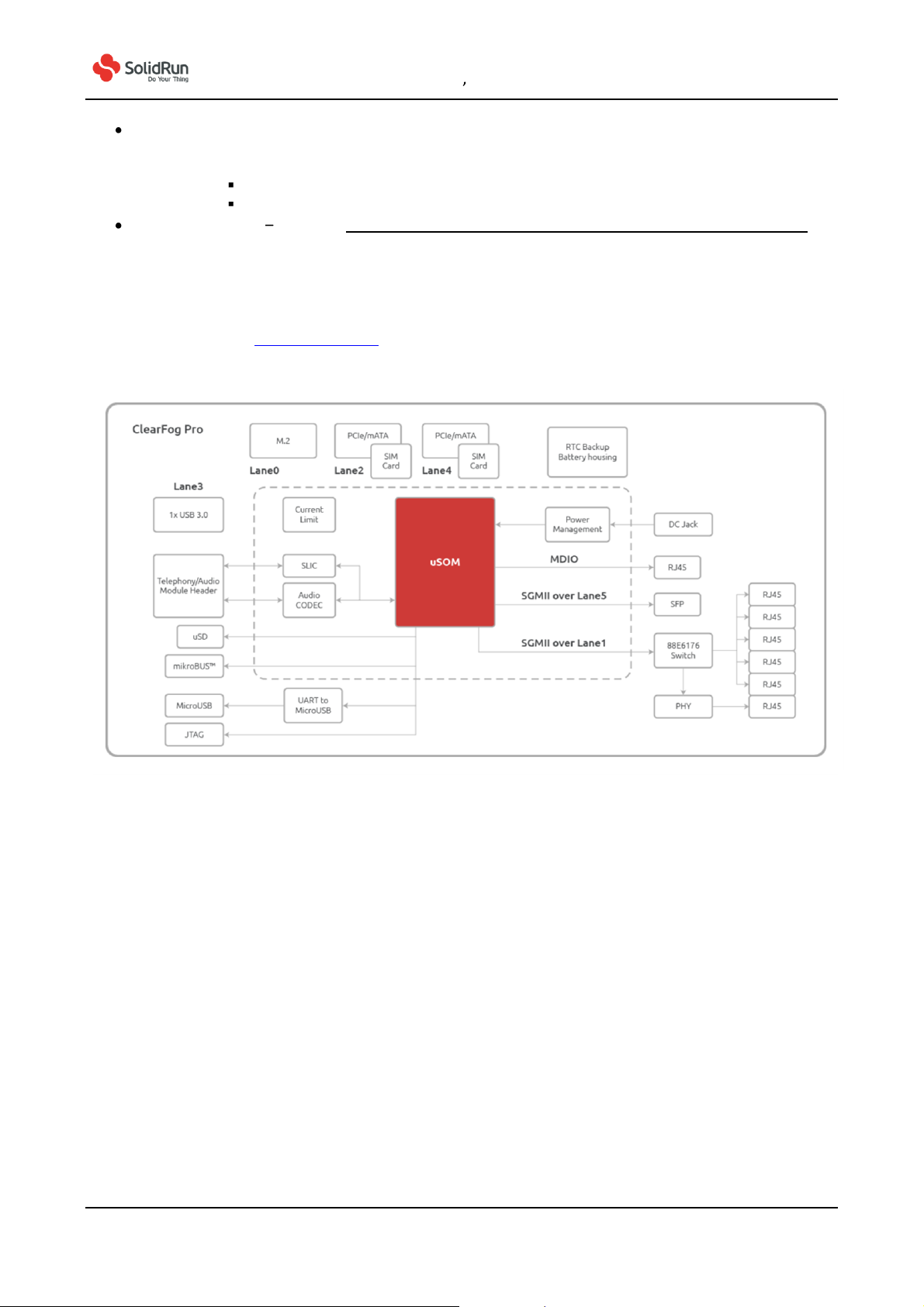
1.3 Block Diagram
SolidRun Clearfog PRO Evaluation Board block diagram is shown here. It displays all relevant interfaces of it. For
further details please visit www.solid-run.com and wiki.solid-run.com:
:

USER S MANUAL JANUARY2017
SolidRun Ltd www.solid-run.com Page 5 of 13
3 Dolev Street, 2495900 Migdal Tefen, Israel
2. MAIN HARDWARE COMPONENTS
This chapter shows the main hardware components and interfaces of the SolidRun Clearfog PRO Evaluation Board,
including the A38x-uSoM MicroSoM.
Top view of SolidRun Clearfog PRO Evaluation Board.
Bottom view of SolidRun Clearfog PROEvaluation Board.

USER S MANUAL JANUARY2017
SolidRun Ltd www.solid-run.com Page 6 of 13
3 Dolev Street, 2495900 Migdal Tefen, Israel
3. CONNECTOR LAYOUT
SolidRun Clearfog PRO Evaluation Board has standard interfaces. The non-standard interfaces are listed here:
1. MicroBus Header
2. TDM Telephony Audio Header
3. Power over Ethernet (PoE) expansion header
Please refer to the previous chapter for their specific location on the board.
The schematics bycomponentscan be foundin ourwiki pages,please lookfor the file underthe product
documentation tab.
USER S MANUAL JANUARY2017
SolidRun Ltd www.solid-run.com Page 7 of 13
3 Dolev Street, 2495900 Migdal Tefen, Israel
4. INSTALLATION AND SWITCHING ON
This chapterexplains how the SolidRun ClearfogPRO Evaluation Boardispackagedand how toprepare it forusage
and how to power it on in its default stage. This relates also to the block diagram in chapter 2.
5.1 Unpacking your SolidRun Clearfog PRO
The package contains:
Clearfog Pro Board
MicroSoM A388
Heat Sink
Power adapter, 110V/220V (optional)
SD card, 8GB (optional) / eMMC
Aluminum Enclosure (optional)
5.2 Power
A suitable external power supply is to be connected to the DC jack, which has the dimensions 5.5 x 2.1 mm. The
power supply needs to be in the range of 9-32VDC. Recommended voltage is 12VDC
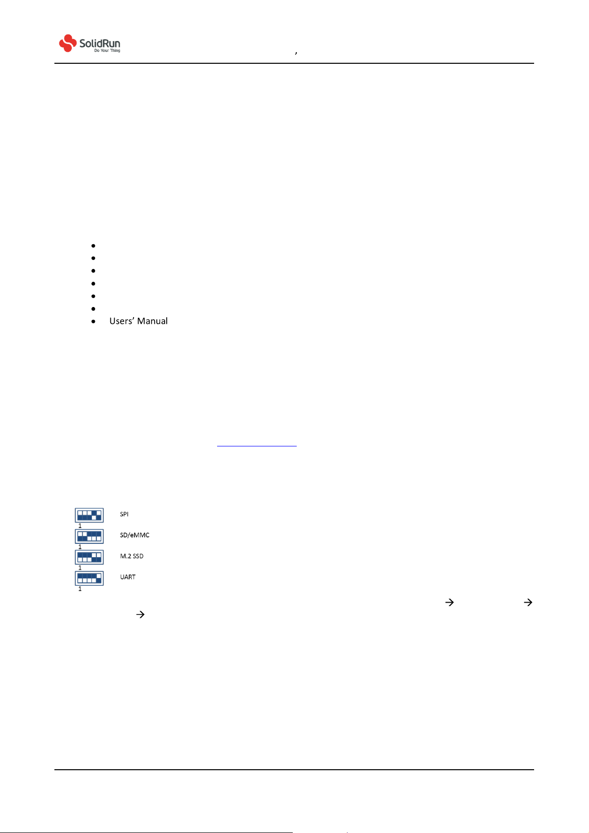
5.3 SD card with operating system and boot select
You will need to download an operating system to an SD card in order to operate the system. You can download
officially released distributions at www.solid-run.com. In addition there are also several community released
distributions available for usage. Once downloaded and flashed to the SD card needs to be inserted into its slot on
the Clearfog PRO Evaluation Board. Before you start using the board, we recommend to make sure to start the
system from SD card by defining the booting media. In order to determine the booting media, please set the S1
switch according to second option (SD/eMMC) as in the following graphic:
For additional insights on operating system, please visit our home page, choose Support Learning Center
getting started downloads.
5.4 Micro USB connectivity (UART to micro-USB)
The Clearfog PRO Evaluation Board can boot also connected to an external terminal on a serial port as a console
by using a micro-USB cable and making a serial connection. This configuration is typically used by developers for
debugging purposes (e.g. kernel or drivers). Such serial console connection is of USB-to-UART type. The
connection speed is tobe set to 115200 bps. Further information is displayed on our wiki page with tags#usbuart
and #serial and #console.
5.5 LEDs

USER S MANUAL JANUARY2017
SolidRun Ltd www.solid-run.com Page 8 of 13
3 Dolev Street, 2495900 Migdal Tefen, Israel
There are port related LEDs on the Clearfog Pro Evaluation Board. These are indicating for example power on,
connection and port activity. For further details, please refer to our wiki.solid-run.com pages.
5.6 Clock options
For frequency configuration a dip switch is used. The default setting is the off-position for all 5 switches as in the
picture here:
Please refer to wiki.solid-run.com for various settings for different frequencies.
5.7 SIMcard holder
It is possible to utilize a Cellular connection by inserting a SIM card into the SIM card holder. Please observe that a
GSM modem needs to be installed utilizing the mini PCIe connection.
5.8 Additional Components
The componentslisted here are also neededfor starting touse theEvaluation Board:
SD card with installed OS (officially released distribution)
Suitable Power Adapter

USER S MANUAL JANUARY2017
SolidRun Ltd www.solid-run.com Page 9 of 13
3 Dolev Street, 2495900 Migdal Tefen, Israel
5. OPERATIONAL DATA
The following tables provides details on operational values:
6.1 Operating Voltage
Item
Minimum
Maximum
Unit
Mains/Power Supply
9.00
32.00
V
6.2 Environmental Data
Item
Minimum
Maximum
Ambient Temperature Range (Commercial)*
0°C
+70°C
Ambient Temperature Range (Industrial)*
-40°C
+85°C**
Humidity (non-condensing)
N/A
75%
Note: Any environmental data ranges are based solely on the carrier board components. The customer needs to
consider its specific thermal andmechanical design for a final product,including but not limited to housing, depending
also on specific operational and environmental conditions.
*Armada 38x SoC has a maximum die temperature of 115°C regardless of ambient temperature and temperature
ratings.
**Safety Note: Please observe that the used RTC has a maximum temperature range of +70°C. In order to utilize the
full range of the industrial temperature range, another RTC has to be used.
USER S MANUAL JANUARY2017
SolidRun Ltd www.solid-run.com Page 10 of 13
3 Dolev Street, 2495900 Migdal Tefen, Israel
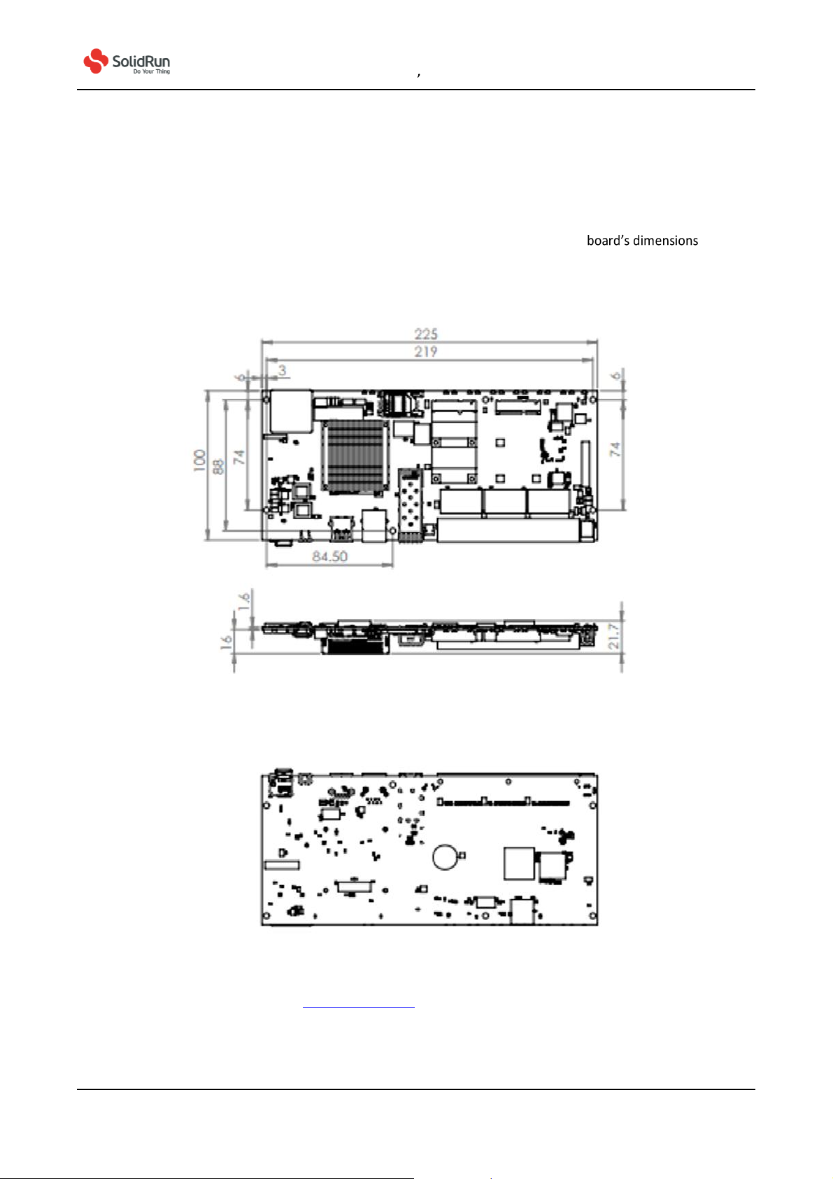
6. MECHANICAL DRAWINGS AND DIMENSIONS
For product design purposes, this chapter provides the SolidRun Clearfog PROEvaluation and
component positions on the board on both sides.
A-Board Base Top, Side and Bottom View [225x100 mm]
CAD files are available for download at www.solid-run.com

USER S MANUAL JANUARY2017
SolidRun Ltd www.solid-run.com Page 11 of 13
3 Dolev Street, 2495900 Migdal Tefen, Israel
7. LEGAL NOTICE AND COMPLIANCES
SolidRun Ltd. (hereinafter terms and conditions of sale,
delivery and payment supplied at the time of purchase order acknowledgement. SolidRun warrants the performance
of its products according to actual specifications at the date of shipment. SolidRun reserves the right to make changes
to its products and specifications or to discontinue any product, product line or service without prior notice.
Customers should make sure to obtain in each case the latest version of relevant product information from SolidRun
and to always verify for themselves that their requirements are met and reference is up to date. Product testing and
all additional quality control techniques are utilized to the extent that SolidRun deems necessary to support their
warranty and warranty terms. Therefore detailed testing of all parameters in any product is not necessarily performed
in full unless required by law or regulation.
In order tominimize risks that may be associated with customer products, applications or services, the customermust
use adequate design and operating safeguards to minimize any possible hazards. SolidRun is not liable for any
applications assistance or customer product design and thus it is the customer to make the
selection and usage of SolidRun products. SolidRun is not liable for any such selection or usage thereinafter and
neither is liable for the usage of any circuitry or components other than completely and entirely embodied in a
SolidRun product. Furthermore SolidRun is not liable for its products commercial fit for any market segment
envisioned by the customer.
SolidRun products are not intended for use in life support systems, appliances, nuclear systems or systems where
malfunction can reasonably be expected to result in personal injury, death or severe property or environmental
damage. Any use of products by the customer for such purposesis completely
SolidRun does not grant any license -expressed or implied- on any patent right, copyright, mask work right, type or
model protection or any other intellectual property right (IPR) of SolidRun covering or relating to any product
combination, hardware, machine, software or process in which its products or services might be or are used. Any
s approval, license,
warranty or endorsement thereof. Any third party trademarks contained in this document belong to the respective
third party owner.
Reproduction of content and information from SolidRun documentsand manuals is permissible only if reproduction is
without alteration and is accompanied by all associated copyright, proprietary and other notices (including this
notice) and related conditions. SolidRun is not liable for any un-authorized alteration of such content and information
or for any reliance related to alterations thereon. Any representations made, warranties given, and/or liabilities
accepted by any person which differ from those contained in this manual
conditions of sale, delivery and payment are made, given and/or accepted at own risk. SolidRun is not
liable for any such representations, warranties or liabilities or for any reliance thereon by any person.
Compliant with:ROHS Standard

USER S MANUAL JANUARY2017
SolidRun Ltd www.solid-run.com Page 12 of 13
3 Dolev Street, 2495900 Migdal Tefen, Israel
8. WARRANTY TERMS AND CONDITIONS
SolidRun guarantees its hardware products against defects in workmanship and material for a period of one (1) year
from the date of shipment. liability shall be, at
sole discretion, toeither repair or replace the defective hardware product at no charge.
This warranty is void if the hardware product has been altered or damaged by an accident, misuse or abuse.
About additional information on warranty and related topics like RMA, please visit www.solid-run.com.
Disclaimer of Warranty
THIS WARRANTY IS MADE IN LIEU OF ANY OTHER WARRANTY, WHETHER EXPRESSED, OR IMPLIED, OF
MERCHANTABILITY, FITNESS FOR A SPECIFIC PURPOSE, NONINFRINGEMENT OR THEIR EQUIVALENTS UNDER THE
LAWS OF ANY JURISDICTION,EXCEPT THE WARRANTYEXPRESSLY STATED HEREIN. THE REMEDIES SET FORTH HEREIN
SHALL BE THE SOLE AND EXCLUSIVE REMEDIES OF ANY CUSTOMER OR PURCHASER WITH RESPECT TO ANY DEFECTIVE
PRODUCT.
Limitation on Liability
UNDER NO CIRCUMSTANCES SHALL SOLIDRUN BE LIABLE FOR ANY LOSS, DAMAGE OR EXPENSES INCURRED OR WITH
RESPECT TO ANY DEFECTIVE PRODUCT. IN NO EVENT SHALL SOLIDRUN BE LIABLE FOR ANY INCIDENTAL OR
CONSEQUENTIAL DAMAGES THAT CUSTOMER MAY SUFFER DIRECTLY OR INDIRECTLY FROM THE USAGE OF ANY
PRODUCT. BYORDERING THE SOLIDRUN CLEARFOG CARRIER BOARD, THE CUSTOMER APPROVES THAT THE SOLIDRUN
CLEARFOG CARRIER BOARD, HARDWARE AND SOFTWARE, WAS THOROUGHLY TESTED AND HAS MET THE
CUSTOMER'S REQUIREMETS AND SPECIFICATIONS.

USER S MANUAL JANUARY2017
SolidRun Ltd www.solid-run.com Page 13 of 13
3 Dolev Street, 2495900 Migdal Tefen, Israel
9. CONTACT INFORMATION AND RESOURCES
SolidRun Ltd Headquarters
3 Dolev Street
3rd Floor
P.O. Box 75
2495900 Migdal Tefen
Israel
Web page: www.solid-run.com
Wiki page: wiki.solid-run.com
Support: support@solid-run.com
Sales: sales@solid-run.com
Other manuals for ClearFog PRO
1
Table of contents
Other SolidRun Motherboard manuals


