SolidRun ClearFog User manual

ClearFog
Base
User Manual

USER MANUAL MARCH 2017
SolidRun Ltd www.solid-run.com Page 2 of 22
7 HaMada Street, Yokne’am Illit, Israel
TABLE OF CONTENTS
1Overview .................................................................................................................................................................. 4
1.1 General Information ...................................................................................................................................... 4
1.2 Summary of Features .................................................................................................................................... 4
1.3 Block Diagram................................................................................................................................................. 5
2Main Hardware Components................................................................................................................................ 6
3Connector Layout ................................................................................................................................................... 8
3.1 Certified Cables.............................................................................................................................................. 8
4Installation and Switching On............................................................................................................................... 9
4.1 Unpacking your SolidRun ClearFog Base ................................................................................................... 9
4.2 Power............................................................................................................................................................... 9
4.3 SD card with operating system and boot select ....................................................................................... 9
4.4 MicroUSB connectivity (UART to microUSB) ........................................................................................... 10
4.5 LEDs................................................................................................................................................................ 10
4.6 SIM card slot/s .............................................................................................................................................. 10
4.7 Additional Required Components............................................................................................................. 11
5Operational Data .................................................................................................................................................. 12
5.1 Operating Voltage....................................................................................................................................... 12
5.2 Environmental Data..................................................................................................................................... 12
6Mechanical Drawings and Dimensions.............................................................................................................. 13
7Warranty Terms and Conditions......................................................................................................................... 14
8Legal Notice........................................................................................................................................................... 15
9Regulatory ............................................................................................................................................................. 16
9.1 Safety notice................................................................................................................................................. 16
9.2 Safety Symbols Notes and information ................................................................................................... 16
9.3 Unpacking...................................................................................................................................................... 17
9.4 Storage, service, cleaning and caring for the product........................................................................... 17
9.5 Operation ...................................................................................................................................................... 17
9.6 AC/DC adapter or power supply - Electrical safety ............................................................................... 18
9.7 Electronic emission notices........................................................................................................................ 20
10 Contact Information and Resources ............................................................................................................. 22

USER MANUAL MARCH 2017
SolidRun Ltd www.solid-run.com Page 3 of 22
7 HaMada Street, Yokne’am Illit, Israel
REVISIONS AND NOTES
Date
Owner
Revision
Notes
01 Aug 2017
Matthew Dunbar
1.1
Full Revision
© 2017 SolidRun Ltd. All Rights Reserved.
All rights on this documentation and the devices are with SolidRun Ltd.
No warranty of accuracy is given concerning the contents of the information contained in this publication.
To the extent permitted by law no liability (including liability to any person by reason of negligence) will
be accepted by SolidRun Ltd., its subsidiaries or employees for any direct or indirect loss or damage
caused by omissions from or inaccuracies in this document. SolidRun Ltd. reserves the right to change
details in this publication without prior notice. Product and company names herein may be the trademarks
of their respective owners.
Verify that you have the most current version of this document from www.solid-run.com

USER MANUAL MARCH 2017
SolidRun Ltd www.solid-run.com Page 4 of 22
7 HaMada Street, Yokne’am Illit, Israel
1OVERVIEW
1.1 GENERAL INFORMATION
The SolidRun ClearFog Base is a high performance Single Board Computer featuring SolidRun’s SOM (A388
SOM). ClearFog Base provides a foundation for building various applications and tailors well to a wide
range of target markets requiring high performance processing power, connectivity & storage interfaces.
The ClearFog Base ensures compact dimensions and low power consumption, utilizing an ARM Cortex A9
Dual core CPU.
SolidRun ClearFog Base Single Board Computer components:
A388 SOM for the ClearFog Base
ClearFog Base Carrier Board
Heat sink
Power adapter - 110V/220V US or EU plug (optional)
Enclosure (optional)
MicroSD card (optional)
Officially released OSS distributions
oOpenWrt
oYocto
1.2 SUMMARY OF FEATURES
Customizable configurations of the ClearFog Base:
Marvell ARMADA 388 series SoC Dual ARM® Cortex™-A9 Core at 1.6 GHz (1.6 GHz commercial /
1.3 GHz Industrial)
1 GB DDR3 RAM (optional up to 2GB RAM)
4 MB NOR Flash [storage memory / boot]
MicroSD based storage (Can be upgraded with an on-board eMMC)
M.2 slot (key type B) supporting 2242 modules including SSD and cellular modems
Mini PCIe slot (also capable of supporting mSATA SSD modules)
SIM Card slot for M.2 based cellular modem. (2nd SIM card slot as an option which can utilize a Mini
PCIe based cellular modem)
Dual 10/100/1000 Mbps Ethernet ports
SFP Port
One USB 3.0 host port
mikroBUS Header supporting serial interfaces such as SPI, UART, etc.
One MicroUSB supporting Serial communication for development purposes using FTDI 230X IC –
Please see more details in our wiki pages at http://wiki.solid-run.com
Power over Ethernet Header (PoE Expansion Header - for optional module development)
Real Time Clock (RTC) with backup battery
Wide range power supply 9-32V
Push button connected to a GPIO.
LEDs:
oOne power indicator
oDual LEDs on each RJ45 Ethernet port
Link / Activity indicator
1000 vs. 10/100 indicator

USER MANUAL MARCH 2017
SolidRun Ltd www.solid-run.com Page 5 of 22
7 HaMada Street, Yokne’am Illit, Israel
1.3 BLOCK DIAGRAM
The SolidRun ClearFog Base Single Board Computer block diagram displays all relevant elements of the
full SBC. For further details please visit www.solid-run.com and wiki.solid-run.com
Figure 1 SolidRun ClearFog Base Block Diagram

USER MANUAL MARCH 2017
SolidRun Ltd www.solid-run.com Page 6 of 22
7 HaMada Street, Yokne’am Illit, Israel
2MAIN HARDWARE COMPONENTS
This chapter highlights the location of the main hardware components and interfaces of the SolidRun
ClearFog Base Single Board Computer, including the A388 SOM.
Figure 2 SolidRun ClearFog Base Top View

USER MANUAL MARCH 2017
SolidRun Ltd www.solid-run.com Page 7 of 22
7 HaMada Street, Yokne’am Illit, Israel
Figure 3 SolidRun ClearFog Base Bottom View

USER MANUAL MARCH 2017
SolidRun Ltd www.solid-run.com Page 8 of 22
7 HaMada Street, Yokne’am Illit, Israel
3CONNECTOR LAYOUT
SolidRun’s ClearFog Base Single Board Computer has standard interfaces. The non-standard interfaces are
listed here:
1. mikroBUS Header
2. Power over Ethernet (PoE Expansion Header - for optional module development)
oPlease refer to the previous chapter for specific locations on the board.
The schematics by components can be found SolidRun’s wiki pages, please look for the file under the
product documentation tab.
3.1 CERTIFIED CABLES
The following is a list of industry-standard cables, sorted by type, with the necessary compliance
requirements that have been proven to work well with the Clearfog product family.
These examples are the cables which SolidRun uses for testing, and should provide enough information to
source products from your prefered cable vendor.
Ethernet cable: Monoprice 24AWG Cat6A 500MHz STP
USB Cable: SuperSpeed USB 3.0 Type A Male to Female Extension Cable in Black
SFP connector: GigaLite GE-GB-P1RT-E SFP module with Monoprice 24AWG Cat6A 500MHz STP
cable
USER MANUAL MARCH 2017
SolidRun Ltd www.solid-run.com Page 9 of 22
7 HaMada Street, Yokne’am Illit, Israel
4INSTALLATION AND SWITCHING ON
This chapter explains the SolidRun ClearFog Base packaging, how to prepare it for initial use and in what
manner to power it on in its default state. Please note that this section references the diagrams in chapter
2.
4.1 UNPACKING YOUR SOLIDRUN CLEARFOG BASE
The package contains:
ClearFog Base Board
A388 SOM
Heat Sink
Power adapter - 110V/220V US or EU plug (optional)
Blank SD card, 8GB (optional) / eMMC (optional)
Aluminum Enclosure (optional)
User Manual
4.2 POWER
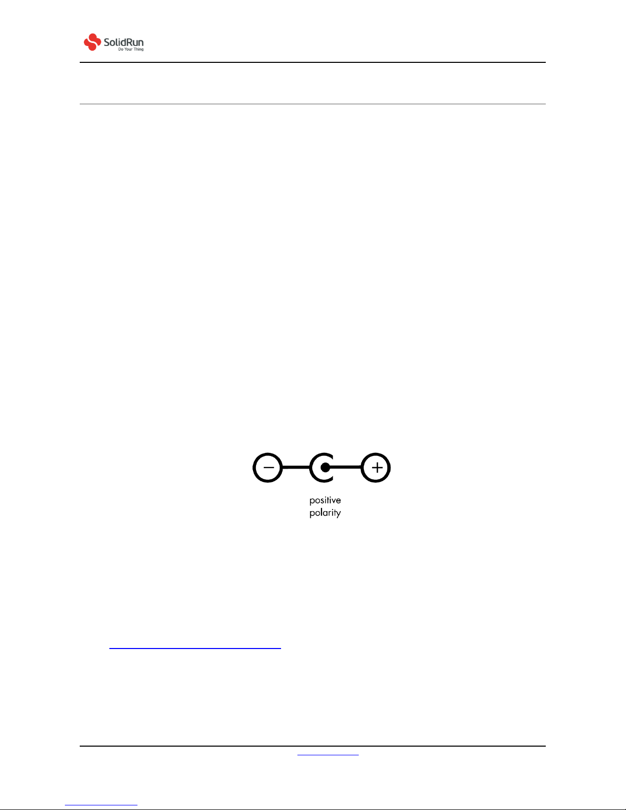
A suitable external power supply must be connected to the DC power socket, which has the
dimensions 5.5mm x 2.1 mm cylindrical barrel connector The power supply must be in the range of 9-
32VDC. Recommended values are: 12VDC/2.5A (no more than 5A)
Please note that the DC jack must have positive polarity in the center pin:
Figure 4 DC Barrel Socket Polarity
4.3 SD CARD WITH OPERATING SYSTEM AND BOOT SELECT
You will need to download an operating system for the ClearFog Base and flash in to a blank SD card in
order to use the system. You can download official release distributions and find flashing instructions
at https://www.solid-run.com/downloads/. In addition there are also several community released
distributions available. Once downloaded and flashed, the SD card with the flashed OS image must be
inserted into the MicroSD slot on the ClearFog Base. Before powering up the board for the first time it
is recommended to select the boot media. In order to configure the boot media to MicroSD, please set
the S1 switch to match the second option from the following table (SD/eMMC):

USER MANUAL MARCH 2017
SolidRun Ltd www.solid-run.com Page 10 of 22
7 HaMada Street, Yokne’am Illit, Israel
Switch 1
Switch 2
Switch 3
Switch 4
Switch 5
SPI
Off
Off
Off
On
Off
SD/eMMC
Off
Off
On
On
On
M.2 SSD
On
On
On
Off
Off
UART
Off
On
Off
Off
On
Table 1 Boot Selection Table
For additional insights on operating system, please visit the Downloads section of our home page.
Additional extensive resources are available in the Support section of our Wiki.
4.4 MICROUSB CONNECTIVITY (UART TO MICROUSB)
The ClearFog Base Single Board Computer has an FTDI 230x UART to USB bridge allowing convenient
connection to the device console. This configuration is typically used by developers for debugging
purposes (e.g. kernel or drivers). Such serial console connection is of USB-to-UART type. The
connection speed should be set to 115200 bps. Further information is displayed on our wiki page with
tags #UART & #serial & #console.
4.5 LEDS
There are multiple LEDs on the ClearFog Base Single Board Computer. These are indicating for
example power on, connection and port activity. Ethernet port related LEDs are embedded in the
RJ45 connectors, while the power indicator LED is located on the ClearFog Base Board. For further
details, please refer to our wiki.solid-run.com pages.
Figure 5 Location of LEDS on the ClearFog Base
4.6 SIM CARD SLOT/S
It is possible to utilize a Cellular connection by inserting a SIM card into the SIM card slot. Please note
that a GSM Cellular modem needs to be installed utilizing the M.2 2242 slot in order to exploit the
cellular connection.

USER MANUAL MARCH 2017
SolidRun Ltd www.solid-run.com Page 11 of 22
7 HaMada Street, Yokne’am Illit, Israel
Please note: If you your ClearFog Base has dual SIM card slots, an additional cellular modem will need
to be installed in the mini PCIe connection in order to utelize the 2nd SIM connection.
4.7 ADDITIONAL REQUIRED COMPONENTS
The components listed here are needed in order to begin using the ClearFog Base Single Board
Computer:
SD card with flashed OS (officially released distributions and flashing instructions can be
downloaded from https://www.solid-run.com/downloads/)
Suitable Power Adapter as explained in section 4.2 of this manual.

USER MANUAL MARCH 2017
SolidRun Ltd www.solid-run.com Page 12 of 22
7 HaMada Street, Yokne’am Illit, Israel
5OPERATIONAL DATA
The following tables provide details on operational values:
5.1 OPERATING VOLTAGE
Item
Minimum
Maximum
Unit
Mains/ Power Supply
9.00
32.00
V DC
Current rating
2
5
A
5.2 ENVIRONMENTAL DATA
Item
Minimum
Maximum
Ambient Temperature Range for enclosed
0°C
+40°C
Ambient Temperature Range* for Commercial PCBA**
0°C
+70°C
Ambient Temperature Range* for Industrial PCBA**
-40°C
+85°C***
Humidity (non-condensing)
10
90%
Note: Environmental data ranges are based solely on the ClearFog Base components. The customer needs
to consider specific thermal and mechanical design for a final product, including but not limited to
housing, taking into account specific operational and environmental conditions.
*Armada 388 SoC has a maximum die temperature of 115°C regardless of ambient temperature and
temperature ratings.
**PCBA refers to assembled PCB boards without enclosure.
***Safety Note: Please observe that the supplied RTC has a maximum temperature range of +70°C. In
order to utilize the full industrial temperature range, the supplied RTC will need to be upgraded.

USER MANUAL MARCH 2017
SolidRun Ltd www.solid-run.com Page 13 of 22
7 HaMada Street, Yokne’am Illit, Israel
6MECHANICAL DRAWINGS AND DIMENSIONS
For product design purposes, this chapter provides the SolidRun ClearFog Base Single Board Computer’s
and component positions on both sides of the board:
Figure 6 ClearFog Base Mechanical Drawings & Dimensions
CAD files are available for download at wiki.solid-run.com

USER MANUAL MARCH 2017
SolidRun Ltd www.solid-run.com Page 14 of 22
7 HaMada Street, Yokne’am Illit, Israel
7WARRANTY TERMS AND CONDITIONS
SolidRun guarantees its hardware products against defects in workmanship and material for a period of
one (1) year from the date of shipment. Under warranty, the customer’s sole remedy and SolidRun’s sole
liability shall be, at SolidRun’s sole discretion, to either repair or replace the defective hardware product at
no charge.
This warranty is void if the hardware product has been altered or damaged by an accident, misuse or
abuse.
For additional information on warranty and related topics like RMA, please visit www.solid-run.com.
Disclaimer of Warranty
THIS WARRANTY IS MADE IN LIEU OF ANY OTHER WARRANTY, WHETHER EXPRESSED, OR IMPLIED, OF
MERCHANTABILITY, FITNESS FOR A SPECIFIC PURPOSE, NONINFRINGEMENT OR THEIR EQUIVALENTS
UNDER THE LAWS OF ANY JURISDICTION, EXCEPT THE WARRANTY EXPRESSLY STATED HEREIN. THE
REMEDIES SET FORTH HEREIN
SHALL BE THE SOLE AND EXCLUSIVE REMEDIES OF ANY CUSTOMER OR PURCHASER WITH RESPECT TO
ANY DEFECTIVE PRODUCT.
Limitation on Liability
UNDER NO CIRCUMSTANCES SHALL SOLIDRUN BE LIABLE FOR ANY LOSS, DAMAGE OR EXPENSES
INCURRED OR WITH RESPECT TO ANY DEFECTIVE PRODUCT. IN NO EVENT SHALL SOLIDRUN BE LIABLE
FOR ANY INCIDENTAL OR CONSEQUENTIAL DAMAGES THAT CUSTOMER MAY SUFFER DIRECTLY OR
INDIRECTLY FROM THE USAGE OF ANY PRODUCT. BY ORDERING THE SOLIDRUN CLEARFOG CARRIER
BOARD, THE CUSTOMER APPROVES THAT THE SOLIDRUN CLEARFOG CARRIER BOARD, HARDWARE AND
SOFTWARE, WAS THOROUGHLY TESTED AND HAS MET THE CUSTOMER'S REQUIREMETS AND
SPECIFICATIONS.

USER MANUAL MARCH 2017
SolidRun Ltd www.solid-run.com Page 15 of 22
7 HaMada Street, Yokne’am Illit, Israel
8LEGAL NOTICE
SolidRun Ltd. (hereinafter “SolidRun”) products and services are sold subject to SolidRun terms and
conditions of sale, delivery and payment supplied at the time of purchase order acknowledgement.
SolidRun warrants the performance of its products according to actual specifications at the date of
shipment. SolidRun reserves the right to make changes to its products and specifications or to discontinue
any product, product line or service without prior notice.
Customers should make sure to obtain in each case the latest version of relevant product information
from SolidRun and to always verify for themselves that their requirements are met and reference is up to
date. Product testing and all additional quality control techniques are utilized to the extent that SolidRun
deems necessary to support their warranty and warranty terms. Therefore detailed testing of all
parameters in any product is not necessarily performed in full unless required by law or regulation.
In order to minimize risks that may be associated with customer products, applications or services, the
customer must use adequate design and operating safeguards to minimize any possible hazards. SolidRun
is not liable for any applications assistance or customer product design and thus it is the customer’s sole
responsibility to make the selection and usage of SolidRun products. SolidRun is not liable for any such
selection or usage thereinafter and neither is liable for the usage of any circuitry or components other
than completely and entirely embodied in a SolidRun product. Furthermore SolidRun is not liable for its
products commercial fit for any market segment envisioned by the customer.
SolidRun products are not intended for use in life support systems, appliances, nuclear systems or systems
where malfunction can reasonably be expected to result in personal injury, death or severe property or
environmental damage. Any use of SolidRun’s products by the customer for such purposes is completely at
the customer’s own risk.
SolidRun does not grant any license -expressed or implied- on any patent right, copyright, mask work right,
type or model protection or any other intellectual property right (IPR) of SolidRun covering or relating to
any product combination, hardware, machine, software or process in which its products or services might
be or are used. Any provision or publication of any third party’s products or services does not constitute
SolidRun’s approval, license, warranty or endorsement thereof. Any third party trademarks contained in
this document belong to the respective third party oner.
Reproduction of content and information from SolidRun documents and manuals is permissible only if
reproduction is without alteration and is accompanied by all associated copyright, proprietary and other
notices (including this notice) and related conditions. SolidRun is not liable for any un-authorized
alteration of such content and information or for any reliance related to alterations thereon. Any
representations made, warranties given, and/or liabilities accepted by any person which differ from those
contained in this manual or in SolidRun’s standard terms and conditions of sale, delivery and payment are
made, given and/or accepted at customer’s own risk. SolidRun is not liable for any such representations,
warranties or liabilities or for any reliance thereon by any person.

USER MANUAL MARCH 2017
SolidRun Ltd www.solid-run.com Page 16 of 22
7 HaMada Street, Yokne’am Illit, Israel
9REGULATORY
This chapter provides regulatory and compliance information about SolidRun’s ClearFog Base.
Certification-related information
Product name: ClearFog Base
9.1 SAFETY NOTICE
Before you begin using this product, please read the following safety information.
Attention to these warnings will help prevent personal injuries and damage to the products
It is your responsibility to use the product in an appropriate manner. This product is designed for use solely
indoor environments or, if expressly permitted, also in the field and must not be used in any way that may
cause personal injury or property damage.
You are responsible if the product is used for any intention other than its designated purpose or in
disregard of SolidRun instructions. SolidRun shall assume no responsibility for such use of the product.
The product is used for its designated purpose if it is used in accordance with its product documentation
and within its performance limits.
9.2 SAFETY SYMBOLS NOTES AND INFORMATION
Throughout this manual, look for the symbols below that highlight safety related information.
DANGER
WARNING
CAUTION
NOTICE
Indicates a hazardous situation which, if not avoided, will result in death
or serious injury.
Indicates a hazardous situation which, if not avoided, could result in
death or serious injury.
Indicates a hazardous situation which, if not avoided, could result in
minor or moderate injury.
Indicates the possibility of incorrect operation which can result in damage to
the product. The word ATTENTION may be used synonymously.
Indicates that information related to safety or system proper
information is provided.

USER MANUAL MARCH 2017
SolidRun Ltd www.solid-run.com Page 17 of 22
7 HaMada Street, Yokne’am Illit, Israel
9.3 UNPACKING
CAUTION
Never turn on or connect to power any equipment when there is evidence of mechanical
damage, fire, exposure to water, or structural damage.
9.4 STORAGE,SERVICE,CLEANING AND CARING FOR THE PRODUCT
CAUTION
When not in use, avoid placing or storing the product in the following places or under the
following conditions:
Ambient temperature above 40°C
Exposed to direct sunlight
Humid or exposed to dust
WARNING
This product does not contain any user replicable or serviceable parts.
Do not take apart or attempt to service the product yourself.
Never remove the cover or any part of the housing of the product
The internal battery is not user replicable.
In the event of an equipment malfunction, all repairs must be performed either by SolidRun
or by an authorized agent. It is the customer responsibility to report the need for service to
SolidRun or to one of the authorized agents. For service information, contact SolidRun
customer support.
Be careful not subject the product to strong impact.
If the product was subjected to a strong impact and/or falling over check carefully for any damage to the
product. If such damage is observed the use of the product must be stopped immediately.
9.5 OPERATION
The product may be operated only under the operating conditions as specified by SolidRun.
When the product is used for an extended period of time, and/or at high ambient
temperature and/or exposed to direct sunlight it is normal for the product body to feel
warm.
CAUTION
Avoid overheating the product.
The product’s ventilation should not be obstructed or blocked. If proper ventilation is not
provided it can result in battery overheating or explosion of the battery resulting fire, burns
or other injuries.

USER MANUAL MARCH 2017
SolidRun Ltd www.solid-run.com Page 18 of 22
7 HaMada Street, Yokne’am Illit, Israel
CAUTION
Avoid overheating the product.
Operating the product in ambient temperature above its specifications may cause
overheating or explosion of the battery resulting fire, burns or other injuries.
DANGER
Stop using the product immediately if it emits smoke or a strange smell, or otherwise
behaves abnormally.
NOTICE
Following are the required operating position and conditions:
Do not place the product on unstable surfaces
Do not place the product on elevated surface and secure it from falling from high places on passerby
Do not place the product on heat-generating surface or near heat emitting devices or direct flame. Verify
that there is sufficient clearance between the product and any other device exhaust warm air
The product operating ambient range is temperature of 0-40 °C (32 to 104 °F) and Relative humidity of 10-
90%. SolidRun recommends that an ambient temperature of 20 to 25 °C (68 to 77 °F) and relative
humidity of 30-50% is maintained during normal operation as this will result in better performance and
longer life of the equipment. Temperature must not exceed the maximum temperature specified
above.
Do not expose the product to moisture or dust.
The product is not liquid-proof; therefore, the equipment must be protected against penetration by
liquids. If the necessary precautions are not taken, the user may suffer electric shock or the product
itself may be damaged, which can also lead to personal injury.
Never use the product under conditions in which condensation has formed or can form in or on the
product, e.g. if the product has been moved from a cold to a warm environment. Penetration by water
increases the risk of electric shock.
9.6 AC/DC ADAPTER OR POWER SUPPLY -ELECTRICAL SAFETY
DANGER
The following information on electrical safety must be observed, failing to follow these
instruction may result in electric shock, fire and/or serious personal injury or death.
Use only the adapter or power supply supplied with the product or adapter or power supply with the
following specifications:
oOutput voltage of 12V and current of at least 2A and not more than 5A
Prior to powering the product and plugging the adapter or power supply to the mains supply, always
ensure that the nominal voltage setting on the adapter or power supply matches the nominal voltage
of the AC supply network.
If extension cords or connector strips are implemented, they must be checked on a regular basis to ensure
that they are safe to use.

USER MANUAL MARCH 2017
SolidRun Ltd www.solid-run.com Page 19 of 22
7 HaMada Street, Yokne’am Illit, Israel
Never use the adapter or power supply if the power cable is damaged. Check the power cable on a regular
basis to ensure that it is in proper operating condition. By taking appropriate safety measures and
carefully laying the power cable, you can ensure that the cable will not be damaged and that no one
can be hurt by, for example, tripping over the cable or suffering an electric shock.
Do not insert the plug into sockets that are dusty or dirty. Insert the plug firmly and all the way into the
socket. Otherwise, sparks that result in fire and/or injuries may occur.
Do not overload any sockets, extension cords or connector strips; doing so can cause fire or electric
shocks.
Do not insert or remove the plug with wet hands.
Never remove the cover or any part of the housing of the adapter or power supply, doing so will expose
circuits and components and can lead to electric shock, injuries, fire or damage to the product.
The adapter or power supply operating ambient temperature range is of 0 to 40°C / 32 to 104 °F (storage
temp range: -20 to 60 ℃/ -04 to 140 °F ) maximum operating altitude is 2000 m ASL,
Use suitable overvoltage protection to ensure that no overvoltage (such as that caused by a bolt of
lightning) can reach the product. Otherwise, the person operating the product will be exposed to the
danger of an electric shock.
The product is not liquid-proof; therefore, the equipment must be protected against penetration by
liquids. If the necessary precautions are not taken, the user may suffer electric shock or the product
itself may be damaged, which can also lead to personal injury.
Never use the product under conditions in which condensation has formed or can form in or on the
product, e.g. if the product has been moved from a cold to a warm environment. Penetration by water
increases the risk of electric shock.
Prior to cleaning the product, disconnect it completely from the power supply. Use a soft, non-linting cloth
to clean the product. Never use chemical cleaning agents such as alcohol, acetone or diluents for
cellulose lacquers.

USER MANUAL MARCH 2017
SolidRun Ltd www.solid-run.com Page 20 of 22
7 HaMada Street, Yokne’am Illit, Israel
9.7 ELECTRONIC EMISSION NOTICES
Federal Communications Commission Declaration of Conformity
The following information refers to ClearFog Base.
This equipment has been tested and found to comply with the limits for a Class B digital device, pursuant
to Part 15 of the FCC Rules. These limits are designed to provide reasonable protection against harmful
interference in a residential installation.
Operation is subject to the following two conditions:
(1) this device may not cause harmful interference, and (2) this device must accept any interference
received, including interference that may cause undesired operation.
Responsible Party: SolidRun Ltd.
7 HaMada St
Yokne’am Illit
Israel
Support: [email protected]
European Union - Compliance to the Electromagnetic Compatibility
(EMC) Directive or Radio Equipment Directive
This product is in conformity with the protection requirements of EU Council Directive 2014/30/EU (from
20 April, 2016) on the approximation of the laws of the Member States relating to electromagnetic
compatibility.
SolidRun Ltd. is not responsible for any radio or television interference caused by using other than
specified or recommended cables and connectors or by unauthorized changes or modifications to this
equipment.
Unauthorized changes or modifications could void the user's authority to operate the equipment.
Table of contents


