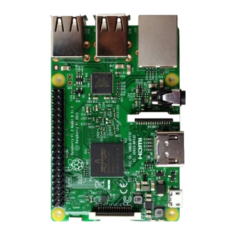
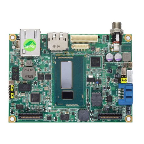
Avnet MaaXBoard AES-MC-SBC-IMX8M-G Instructions for use

MaaXBoard
(AES-MC-SBC-IMX8M-G)
Hardware User Manual
V1.1

MaaXBoard HW UserManual V1.1
http://www.avnet.me/maaxboard 2
Copyright Statement:
The MaaXBoard single board computer (partnumber: AES-MC-SBC-IMX8M-G) and its related
intellectual property are owned by Avnet Manufacturing Services.
Avnet Manufacturing Services has the copyright of this document and reserves all rights. Any part of
the document should not be modified, distributed or duplicated in any approach and form with the
written permission issued by Avnet Manufacturing Services.
Disclaimer:
Avnet Manufacturing Services does not take warranty of any kind, either expressed or implied, as to
the program source code, software and documents provided along with the products, and including,
but not limited to, warranties of fitness for a particular purpose; The entire risk as to the quality or
performance of the program is with the user of products.
Regulatory Compliance:
MaaXBoard single board computer has passed the CE & FCC certification.

MaaXBoard HW UserManual V1.1
http://www.avnet.me/maaxboard 4
Catalog
Revision History ........................................................................................................................................... 3
1.1 Brief Introduction .................................................................................................................... 8
1.2 System Block Diagram ........................................................................................................... 8
1.3 Packing List ............................................................................................................................ 9
1.4 Product Specifications............................................................................................................ 9
1.5 Other Customer Provide Parts ............................................................................................. 10
1.6 Interface Locations ................................................................................................................11
1.7 Product Dimensions (mm).................................................................................................... 12
1.8 Height Distribution (mm)....................................................................................................... 13
2.1 MaaXBoard Hardware Installation and Start up .................................................................. 14
2.1.1 Installation.................................................................................................................... 14
2.1.2 Booting Configuration .................................................................................................. 14
2.2 Details of Interfaces.............................................................................................................. 15
2.2.1 POWER IN................................................................................................................... 15
2.2.2 Button........................................................................................................................... 16
2.2.3 HDMI............................................................................................................................ 17
2.2.4 USB Host ..................................................................................................................... 19
2.2.5 RJ-45............................................................................................................................ 21
2.2.6 Camera ........................................................................................................................ 23
2.2.7 40 Pin Expansion Pin Header...................................................................................... 26
2.2.8 Wi-Fi/Bluetooth (Optional) ........................................................................................... 30
2.2.9 Micro SD Card (TF Card)............................................................................................. 32
2.2.10 Extend Interface J26.................................................................................................... 34
2.2.11 Extend Interface J23.................................................................................................... 36

MaaXBoard HW UserManual V1.1
http://www.avnet.me/maaxboard 5
2.2.12 MIPI-DSI ...................................................................................................................... 37
2.3 Introduction of Peripheral Chips........................................................................................... 40
2.3.1 AR8035 ........................................................................................................................ 40
2.3.2 BD71837 ...................................................................................................................... 40
2.3.3 AW-CM256SM ............................................................................................................. 40
3.1 Software................................................................................................................................ 41
4.1 Technical Support................................................................................................................. 42
4.2 Warranty Conditions ............................................................................................................. 42

MaaXBoard HW UserManual V1.1
http://www.avnet.me/maaxboard 6
Figure
Figure 1.1 MaaXBoard System Block Diagram.................................................................................... 8
Figure 1.2 MaaXBoard Top View .........................................................................................................11
Figure 1.3 MaaXBoard Bottom View ...................................................................................................11
Figure 1.4 Product Dimensions .......................................................................................................... 12
Figure 1.5 Height Distribution ............................................................................................................. 13
Figure 2.1 USB Type C Slot................................................................................................................ 15
Figure 2.2 Button................................................................................................................................. 16
Figure 2.3 HDMI Connector................................................................................................................ 17
Figure 2.4 Double-layer USB Host connector .................................................................................... 19
Figure 2.5 RJ45 Connector................................................................................................................. 21
Figure 2.6 Camera Connector ............................................................................................................ 23
Figure 2.7 2.54mm Double Row Pin Header...................................................................................... 26
Figure 2.8 40Pin Pin Header Pin1 Position ........................................................................................ 27
Figure 2.9 IPEX Antenna Connector .................................................................................................. 30
Figure 2.10 Onboard Ceramic Antenna.............................................................................................. 31
Figure 2.11 Micro SD Card Slot .......................................................................................................... 32
Figure 2.12 12Pin Wafer Connector ................................................................................................... 34
Figure 2.13 12Pin Wafer Connector ................................................................................................... 36
Figure 2.14 30 Pin FPC Connector (MIPI-DSI) .................................................................................. 37

MaaXBoard HW UserManual V1.1
http://www.avnet.me/maaxboard 7
Table
Table 2.1 HDMI Pin Definitions ........................................................................................................... 18
Table 2.2 USB Interface Pin Definition ............................................................................................... 20
Table 2.3 Ethernet Interface Pin Definition ......................................................................................... 22
Table 2.4 Camera Connector Pin Definition ....................................................................................... 24
Table 2.5 40 Pin Expansion Pin Header Definition............................................................................. 27
Table 2.6 Antenna Connector Pin Definition....................................................................................... 30
Table 2.7 Micro SD Card Slot Pin Definition ....................................................................................... 33
Table 2.8 12Pin Definition ................................................................................................................... 35
Table 2.9 J23 Pin Definition ................................................................................................................ 36
Table 2.10 J16 Pin Definition .............................................................................................................. 38

MaaXBoard HW UserManual V1.1
http://www.avnet.me/maaxboard 8
Chapter 1 Product Overview
1.1 Brief Introduction
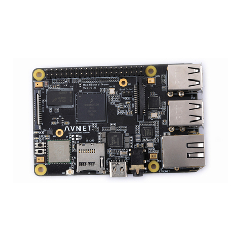
MaaXBoard is a development board for makers, designed by Avnet Manufacturing Services. The
MaaXBoard is a single board computer based on NXP IMX8M SOC series, which can be used for the
areas such as medical instruments, video surveillance, communications, IOT, makers and so on.
In the design of a compact body size, it is provided with rich resources of peripheral interface, include:
Gigabit Ethernet interface, USB 3.0 interface, MIPI-DSI interface, MIPI-CSI interface, HDMI interface,
Micro SD Card interface, UART interface, GPIO interface, Wi-Fi/Bluetooth interface, etc.
1.2 System Block Diagram
I.MX8M
BD71837MWV
5V
32 bits
8 bits
4 bits
ETHERNET
AR8035
USB3.0
PWR_EN USB
SWITCH
HDMI
MIPI CSI
SDIO
PCM
UART
GPIO
MIPI DSI
5V
USB
TypeC
POWER
TF CARD
eMMC
WiFi/BTAntenna
EXP
CON
RGMII RJ45
USB3.0
Double-Deck
HDMI
CON
MIPI CSI
CON
MIPI DSI
CON
I2C1
I2C1
I2C4
1.00mm
Wafer
SAI1
SPI
UART2、UART3
I2C2、I2C3
SAI2
32.768KHz
27MHz27MHz25MHz
25MHz
37.4MHz
2*1GB
DDR4
USB3.0
Figure 1.1 MaaXBoard System Block Diagram

MaaXBoard HW UserManual V1.1
http://www.avnet.me/maaxboard 9
1.3 Packing List
1 ×MaaXBoard
1 × Desiccant
1 × Anti-static Bag
1 × Safety Flyer
1 × Quick Start Guide
2 × Electrostatic Foam
1 × Box
1.4 Product Specifications
General Specifications:
Operating Temperature: 0~70°C (When the CPU loads heavy, need a heatsink)
Power Supply: 5V/3A (Power Adapter)
Operating Humidity: 20% ~ 90% (non-condensing)
Dimensions: 85mm × 55mm
PCB Layers:10Layers
Communication Interface:
1 × 40 Pin IO Interface (Expand I2C, SPI, UART, I2S Interface)
1 × MIPI-CSI Camera Interface
1 × MIPI-DSI Display Interface
1 ×Gigabit Ethernet interface (RJ45)
2 × USB3.0 Host
1 × Micro SD Card (TF Card) Interface
1 × 8bits and 1x 7bits GPIO Interface (Support Audio peripheral expand)
1 × HDMI 2.0 Interface
1 × Power Interface (USB Type C Connector)
1 × Power Button
2 × User Button
1 × Wi-Fi/Bluetooth
2 × User LED

MaaXBoard HW UserManual V1.1
http://www.avnet.me/maaxboard 10
1.5 Other Customer Provide Parts
To use the various functions of MaaXBoard, customer should also provide the following parts which are
not contained in MaaXBoard Packages.
1 × USB to serial cable (TTL)
1 × 1Gbps Network Cable
1 × Camera Module
1 × MIPI-DSI Displayer
1 × 5V/3A Power Supply (USB Type C Interface)
1 × HDMI Cable
1 × HDMI Displayer
Other tools needed to implement related function

MaaXBoard HW UserManual V1.1
http://www.avnet.me/maaxboard 14
Chapter 2 Introduction of Hardware System
This chapter will introduce the structure, expansion and peripheral interfaces of MaaXBoard hardware
system in details.
2.1 MaaXBoard Hardware Installation and Start up
2.1.1 Installation
Before powering up the MaaXBoard, you need to connect all necessary peripheral devices, then power
on the board.
2.1.2 Booting Configuration
According to the manufactured configuration, MaaXBoard supports two boot modes: boot from Micro SD
card or boot from eMMC. By default, the AES-MC-SBC-IMX8M-G only supports SD Card boot. Both the
SD Card foot print and eMMC footprint are on top of each other so only one or the other can be populated
at the same time. If interested in eMMC configuration, Avnet does offer BOM customization services to
populated the eMMC footprint over the SD Card footprint. Contact customize@avnet.com for details.
These two boot modes are mutually exclusive. If users choose to boot from Micro SD card, they should
burn the latest image to the card on PC, then install the card to the board, refer to the software user
manual. If users choose to boot from eMMC, just power on the board.
Note: If the eMMC firmware is destroyed by accident, users could update the eMMC image in USB
Download mode. Please operate carefully and follow the steps in software user manual strictly to avoid
damaging the product.

MaaXBoard HW UserManual V1.1
http://www.avnet.me/maaxboard 15
2.2 Details of Interfaces
This section will introduce the constructions, principles, interface definitions and considerations of use of
MaaXBoard peripherals in detail, so that users may have a deep understanding of the hardware circuitry
of the board.
2.2.1 POWER IN
MaaXBoard use a USB Type C interface as the +5V power in. Note that the USB Type C interface only
provides power supply function, do not support data communication.
The Power adapter should support 3A or above current output.
Figure 2.1 USB Type C Slot

MaaXBoard HW UserManual V1.1
http://www.avnet.me/maaxboard 17
2.2.3 HDMI
Powerful video display is an important feature of MaaXBoard. The HDMI 2.0 interface support up to 4096
x 2160 at 60Hz display output.
J9 is the interface for connecting an HDMI display device on the MaaXBoard, which is a standard HDMI
19Pin connector. Its specification and dimension as follows:
Figure 2.3 HDMI Connector

MaaXBoard HW UserManual V1.1
http://www.avnet.me/maaxboard 18
Table 2.1 HDMI Pin Definitions
HDMI(J9)
Pin Signal Name Ball Description Signal Type
1 HDMI_TX2+ K4 HDMI data 2 differential positive Differential Data
2 GND Ground
3 HDMI_TX2- K3 HDMI data 2 differential negative Differential Data
4 HDMI_TX1+ J4 HDMI data 1 differential positive Differential Data
5 GND Ground
6 HDMI_TX1- J3 HDMI data 1 differential negative Differential Data
7 HDMI_TX0+ K6 HDMI data 0 differential positive Differential Data
8 GND Ground
9 HDMI_TX0- K5 HDMI data 0 differential negative Differential Data
10 HDMI_CLK+ J6 HDMI clock differential positive Differential Data
11 GND Ground
12 HDMI_CLK- J5 HDMI clock differential negative Differential Data
13 HDMI_CEC W4 HDMI consumer electronic control IO
14 NC No Connection
15 HDMICONN_I2CSCL U5 HDMI display data channel clock
IO
16 HDMICONN_I2CSDA T7 HDMI display data channel data
17 GND Ground Ground
18 5V_VDD Power
19 HDMICONN_HPLG K1 HDMI display hot plug detect IO
20 GND_SHELDS
Ground
21 GND_SHELDS
22 GND_SHELDS
23 GND_SHELDS

MaaXBoard HW UserManual V1.1
http://www.avnet.me/maaxboard 19
2.2.4 USB Host
MaaXBoard provides a Double-layer USB Host connector (J5), the two USB port are two independent
controllers, and each one could provide full speed USB3.0 data communication function, used to extend
external devices in USB protocol.
Figure 2.4 Double-layer USB Host connector

MaaXBoard HW UserManual V1.1
http://www.avnet.me/maaxboard 20
Table 2.2 USB Interface Pin Definition
USB Connector(J5)
Pin Signal Name Ball Description Signal Type
1 VBUS1 D14 Power
2 USB1_HOST_DN B14 USB1 PHY USB2.0 differential signal pair negative
Differential signal
3 USB1_HOST_DP A14 USB1 PHY USB2.0 differential signal pair positive
4 GND Ground
5 USB1_HOST_RXN B12 USB1 PHY USB3.0 received differential signal pair
negative Differential signal
6 USB1_HOST_RXP A12 USB1 PHY USB3.0 received differential signal pair
positive
7 GND Ground
8 USB1_HOST_TXN B13
USB1 PHY USB3.0 transmit differential signal pair
negative Differential signal
9 USB1_HOST_TXP A13
USB1 PHY USB3.0 transmit differential signal pair
positive
10 VBUS2 D9 Power
11 USB2_HOST_DN B10 USB2 PHY USB2.0 differential signal pair negative
Differential signal
12 USB2_HOST_DP A10 USB2 PHY USB2.0 differential signal pair positive
13 GND Ground
14 USB2_HOST_RXN B8 USB2 PHY USB3.0 received differential signal pair
negative Differential signal
15 USB2_HOST_RXP A8 USB2 PHY USB3.0 received differential signal pair
positive
16 GND Ground
17 USB2_HOST_TXN B9 USB2
PHY USB3.0 transmit differential signal pair
negative Differential signal
18 USB2_HOST_TXP A9
USB2 PHY USB3.0 transmit differential signal pair
positive Differential signal
S1 Case Earth Earth Ground
Other manuals for MaaXBoard AES-MC-SBC-IMX8M-G
1
Table of contents
Other Avnet Single Board Computer manuals
Avnet
Avnet MaaXBoard Mini Instructions for use
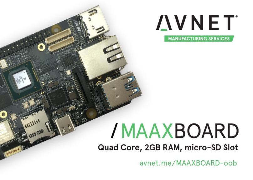
Avnet
Avnet MAAXBOARD User manual
Avnet
Avnet SMARC MSC SM2S-IMX8M User manual

Avnet
Avnet MaaXBoard Mini User manual

Avnet
Avnet Reach Further Ultra96-V2 User manual
Avnet
Avnet MaaXBoard AES-MC-SBC-IMX8M-G User manual

Avnet
Avnet MaaXBoard Mini User manual
Avnet
Avnet MAAXBOARD User manual

Avnet
Avnet MAAXBOARD User manual
Avnet
Avnet ZUBOARD 1CG User manual


